1
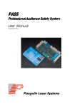
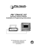
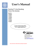
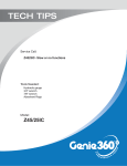
Flow Loop User’s manual - 1 Flow Loop User’s Manual Warnings 240 Volt AC – handle with care Piping under pressure – Drain before disconnecting pipe unions Use water as working fluid – Not designed for other fluids Use standard lifting practices when moving Main Enclosure Do not deadhead the pump Do not run pump dry Do not open either Enclosure while Pump/Motor is running Setup and configuration 1. Check unions to make sure they are tightened sufficiently. Close Valves 2 & 3 to prevent fluid from draining. 2. Open Valve 1 to allow fluid to fill piping system. Fill bucket 2/3 full with water. 3. Check piping system for any signs of leakage. If there is leakage, drain the system and repair as necessary. Valve 1 Valves 2 & 3 Figure 1 - Valve Locations Flow Loop User’s manual - 2 4. Plug 240 VAC cord from Variable Frequency Drive (VFD) into receptacle on Emergency Stop (EStop) Enclosure. 5. Push down E-Stop button. 6. Plug 240 VAC power cord into power supply and E-Stop Enclosure. 7. Plug 120 VAC power cord into power supply while keeping the Power Outlet Strip set to OFF. 8. Pull up the E-Stop button to allow power to the VFD. The VFD screen should read “STOP.” 9. Turn on Power Outlet Strip. Programmable Logic Controller (PLC) should power on. 10. Plug desired sensors into corresponding input on back of Main Enclosure. Make sure VFD communications is connected to allow PLC to control the VFD. Main Enclosure VFD Communications E-Stop Button E-Stop Enclosure Power Outlet Strip, 120 VAC VFD 120 VAC Line 240 VAC Line Figure 2 - Power Layout Flow Loop User’s manual - 3 Running the system 1. Complete the setup. 2. Follow directions in the PLC User’s Manual. NOTE: IF ANY PROBLEMS ARISE IN THE SETUP OR RUNNING OF THIS SYSTEM PRESS THE RED EMERGENCY STOP BUTTON TO CUT OFF 240 VAC POWER TO THE VFD, PUMP AND MOTOR. WAIT FOR PUMP/MOTOR TO COMPLETELY POWER DOWN AND STOP RUNNING BEFORE APPROACHING SYSTEM. CUT OFF 120 VAC POWER BY POWERING OFF OUTLET STRIP AND/OR UNPLUG FROM OUTLET.