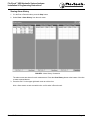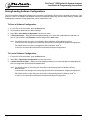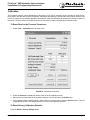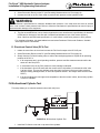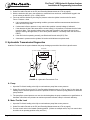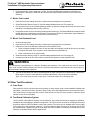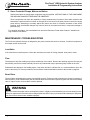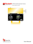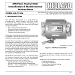
1
Hydraulic System Analyzer
Installation & Programming Instructions
8635 Washington Avenue ■ Racine, WI 53406
Tel: 800-433-5263 or 262-639-6770
Fax: 800-245-3569 or 262-639-2267
E-Mail: [email protected]
www.flo-tech.com
Flo-Check ® USB Hydraulic System Analyzer
Installation & Programming Instructions
Table of Contents
Overview..........................................................................................................................................................................4
Specifications ..................................................................................................................................................................4
Material .....................................................................................................................................................................4
Power ........................................................................................................................................................................5
Environmental ...........................................................................................................................................................5
Performance .............................................................................................................................................................5
Calibration .................................................................................................................................................................5
Model Number Designations .....................................................................................................................................6
General Information ..................................................................................................................................................6
Installing the Software .....................................................................................................................................................7
Connecting the Hydraulic Analyzer to Your Computer for the First Time.........................................................................7
Software Overview ..........................................................................................................................................................8
Running the Software and Viewing Real-Time Data .......................................................................................................9
Recording Measurements to a File..................................................................................................................................9
To Record a File ......................................................................................................................................................10
To Start Recording a File while in Run Mode .......................................................................................................... 11
When Entering Run or Record Mode ...................................................................................................................... 11
Recording Modes .................................................................................................................................................... 11
Log Interval ....................................................................................................................................................................12
Changing Measurement Units .......................................................................................................................................12
Using the Graph ............................................................................................................................................................13
Viewing Graph History ............................................................................................................................................13
Displaying and Hiding Individual Graph Plots .........................................................................................................13
Adjusting the Graph Scales ....................................................................................................................................13
Displaying Graph Gridlines .....................................................................................................................................13
Clearing the Graph ..................................................................................................................................................13
Using the Alarms ...........................................................................................................................................................13
Changing Alarm Settings ........................................................................................................................................14
Resetting the Alarms ...............................................................................................................................................14
Viewing Alarm History .............................................................................................................................................15
Saving/Loading Software Configurations ......................................................................................................................16
To Save a Software Configuration ..........................................................................................................................16
To Load a Software Configuration...........................................................................................................................16
Calibration .....................................................................................................................................................................17
To Reset Zero for the Pressure Transducer ............................................................................................................17
To Reset Factory Calibration Defaults ....................................................................................................................17
Test Procedures.............................................................................................................................................................18
Standard Test Conditions ........................................................................................................................................18
"Tee" Test ................................................................................................................................................................18
Inline System Test ...................................................................................................................................................20
Control Valve and Bi-directional Hydraulic Motor Test ............................................................................................21
Bi-directional Cylinder Test......................................................................................................................................23
Hydrostatic Transmission Diagnostics ....................................................................................................................24
Other Test Procedures ............................................................................................................................................25
Maintenance / Troubleshooting .....................................................................................................................................26
Load Valve ..............................................................................................................................................................26
Flow ........................................................................................................................................................................26
Burst Discs ..............................................................................................................................................................26
Flow vs Pressure Drop Charts.......................................................................................................................................28
Return Goods Authorization ..........................................................................................................................................29
Waste Electrical and Electronic Equipment (WEEE) Directive ......................................................................................29
Warranty ........................................................................................................................................................................30
Form #FLIT 560 09/10
Page 3
Flo-Check ® USB Hydraulic System Analyzer
Installation & Programming Instructions
Overview
The Flo-Check® USB Hydraulic System Analyzer can be used as a stationary or portable tester for both industrial
and mobile hydraulic system diagnostics, and analysis of the prognostic health of a hydraulic system. It features flow,
pressure, and temperature sensors that are monitored by a data acquisition module. This module records the operating
parameters of the system and transfers them to the user’s laptop via the USB port.
The custom software utility is a Windows®-based application which is compatible with Windows Vista®, Windows XP
and Windows 2000. This intuitive software configures the displayed information into user-selected engineering units
and provides real-time graphics with instantaneous readings and trends for all three measurement parameters. The
software also permits the data to be saved for export into a spreadsheet program.
The Hydraulic System Analyzer is powered through the USB port of a PC making it easy to setup and ideal for portable
applications. Interfaced to the PC application, the Hydraulic Analyzer offers a straightforward method of monitoring
system parameters complete with data acquisition.
Specifications
Material
Housing:
Turbine Rotor:
Rotor Supports:
Seals:
Ball Bearings:
Hub Cones:
Temperature Probe:
Valve:
Spool/Sleeve:
Straightening Sections:
Ports:
Magnetic Pick-up
Body:
Nut:
Electronic Case:
6013-T351 Anodized aluminum
T416 Stainless steel
6061-T6 Aluminum
Viton® standard; EPR optional
440 C Stainless steel
6061-T6 Aluminum alloy
T303 Stainless steel
12L14 Steel body with 303 SS seat
12L14 Steel
6061-T6 Aluminum
SAE Straight thread O-ring boss, female, J1926/1; BSPP ISO1179
12L14 Steel, electroless nickel plate
12L14 Steel, electroless nickel plate
Cold rolled steel, black zinc plate with clear seal
Power
USB Power:
USB Voltage Tolerance:
Current:
+5 VDC (supplied through USB port of a PC)
+4.6 VDC min, +5.25 VDC max
100 mA, typ
Environmental
Pressure Rating:
Operating Pressure:
Internal Valve By-pass:
Pressure Drop:
Fluid Temperature:
Ambient Temperature:
Storage Temperature:
Humidity:
Page 4
6000 PSI (414 Bar) maximum with a 3:1 safety factor;
capable of 10,000 PSI (689 Bar) transients
<6000 PSI (414 Bar, 41.4 MPa, 420 kg/cm²);
capable of 10,000 PSI (689 Bar) transients
7500 PSI DP
See ∆P charts on page 28
-4 to +300 °F (-20 to +150 °C)
+32 to +185 °F (0 to +85 °C)
-40 to +185 °F (-40 to +85 °C)
0-90%, non-condensing
Form #FLIT 560 09/10
Flo-Check ® USB Hydraulic System Analyzer
Installation & Programming Instructions
Performance
Flow
Accuracy:
Repeatability:
Pressure
Accuracy:
Stability:
Zero Offset:
TC Zero and TC Span:
Response Time:
Temperature
Absolute Error:
(over range of 0 to 185 °F)
Nonlinearity:
Repeatability:
Data Acquisition
Sample Rate:
PC Screen Update/Record Rate
Flow:
Temperature:
Pressure:
<±1% of reading @ 32 cSt
±0.2%
<±0.5% BFSL
<±0.25% of full scale
<±2% of full scale
<±1.5% of full scale
0.2 milliseconds
±2.7 °F (±1.5 °C)
±0.7 °F (±0.4 °C)
±0.2 °F (±0.1 °C)
10 kHz
1 second (average 10K samples)
1 second (average 10K samples)
1 second (min, max, average 10K samples)
Calibration
Testers are calibrated with 0.876 specific gravity, 150 SUS (32 cSt) Mobil / DTE 24 hydraulic oil. Standard calibration
is done using 5 points and is traceable to NIST, ISO 9001. An optional 10 point calibration can be performed for
increased accuracy.
Model Number Designations
MODEL
NUMBER
Form #FLIT 560 09/10
NOMINAL
PORT SIZE
FLOW
RATE
F7164
SAE 12
2 - 30 GPM
F7160
SAE 16
3 - 85 GPM
F7161
SAE 24
7 - 199.9 GPM
F7165
G-3/4
7.5 - 113.6 LPM
F7162
G-1
15 - 321 LPM
F7163
G-1-1/2
26 - 757 LPM
Page 5
Flo-Check ® USB Hydraulic System Analyzer
Installation & Programming Instructions
CAUTION
Read instructions thoroughly before installing the tester. If you have any questions regarding product installation or
maintenance, call your local supplier or the factory for more information.
General Information
The power measurements are derived from the product of flow and pressure.
H.P. = GPM × PSI
1714
H.P. = liters/min × kg/cm²
456.2
H.P. = liters/min × Bar
447.40
H.P. = liters/min × MPa
44.74
kW = liters/min × kg/cm²
611
kW = liters/min × Bar
600
kW = liters/min × MPa
60
1. Make all tests at the same operating temperature to ensure consistency of results. A typical operating
temperature for mobile machinery is 150 °F (66 °C).
2. Testing will be easier and faster if quick disconnect couplers are used to install the Flo-Check USB Hydraulic
System Analyzer.
3. Complete descriptions of the following basic hydraulic tests using the Flo-Check USB Hydraulic System
Analyzer can be found starting on page 18:
a. "Tee" Test
b. Inline System Test
c.
Control Valve and Bi-directional Hydraulic Motor Test
d. Bi-Directional Cylinder Test
e. Hydrostatic Transmission Diagnostics
CAUTION
The information in this manual is for general application only. Any information furnished by the manufacturer of the
machine’s hydraulic components should be followed. Specific systems may require specific test procedures.
4. A preliminary check of the hydraulic system’s oil supply, pump speed, oil lines, and cylinder rods, as well as
an external leak check, should be made prior to installing the Flo-Check.
Page 6
Form #FLIT 560 09/10
Flo-Check ® USB Hydraulic System Analyzer
Installation & Programming Instructions
Installing the Software
To install the software package on your computer, perform the following steps:
1. Close all applications you have running.
2. Insert the Flo-Check USB Hydraulic System Analyzer CD into your CD drive.
If you have the auto-run feature enabled on your computer, the installation prompts will automatically be
displayed.
Note: If auto-run is not enabled, use Windows Explorer to navigate to the root directory on the CD. Doubleclick on the setup.exe file to begin the installation.
3. Follow the installation prompts to complete the installation.
4. After a successful installation, a dialog will be displayed asking to restart the computer.
Select Yes.
Note: If you wish to wait to reboot the computer, select ‘No’. However, you will need to reboot before initial
use for proper operation.
5. The installation creates two shortcuts on the computer; one on the desktop and the second in the START –
PROGRAMS – FLO-TECH Windows menu.
Connecting the Hydraulic Analyzer to Your Computer for the First Time
The Flo-Check USB Hydraulic System Analyzer connects to your computer through a USB port. A cable is shipped
with the unit, but any standard USB A Male to USB B Male cable can be used. The initial connection is easy and uses
standard drivers within Windows that do not require special driver installation by the operator.
► The Hydraulic Analyzer interface uses the Microsoft Human Interface Driver (HID). This driver is installed
with Windows operating systems that support USB.
► The first time you connect the device to your PC, your computer automatically detects it and configures the
necessary drivers. No third-party device drivers need to be installed.
► The Hydraulic Analyzer interface is plug-and-play. You can connect it to the computer before or after you
install the software, and without shutting the computer off.
Note: Before connecting the Hydraulic Analyzer to the computer, download and install the latest Microsoft Windows
updates. For Windows XP, there is a Hotfix KB822603 that is installed to address a serious error within Windows XP
and the use of USB devices.
To connect the Hydraulic Analyzer to your computer:
1. Connect the USB cable to the Hydraulic Analyzer and then plug the other end into a USB port on the
computer.
2. The first time the Hydraulic Analyzer is connected to the computer, several “Found New Hardware” balloons
or dialogs pop up. This is normal.
3. Once the Hardware has been found and installed, the last balloon or dialog states “Your new hardware is
installed and ready to use.” At this point, the Hydraulic Analyzer interface has been successfully installed and
can be used with the software application.
Form #FLIT 560 09/10
Page 7
Flo-Check ® USB Hydraulic System Analyzer
Installation & Programming Instructions
Software Overview
The software provides a real-time graphical and digital interface for monitoring and/or recording pressure, temperature,
and flow rate parameters from the Hydraulic Analyzer. In addition to the graphical and digital displays, the main screen
also consists of a menu bar, buttons with common functions, and alarm indicators.
FIGURE 1 - Flo-Check USB Hydraulic Analyzer Screenshot
Measurement
(over a 1 second time period)
Color
Indication
Average Pressure
Green
Minimum Pressure
Dark Green
Alarm
Indication
Digital
Indication
Graphical
Display
Record to
File
●
●
●
●
●
●
Maximum Pressure
Dark Green
●
●
Average Temperature
Blue
●
●
●
●
Average Flow Rate
Yellow
●
●
●
●
Average Power
Orange
●
●
TABLE 1 - Measurement Display and Record Features
Page 8
Form #FLIT 560 09/10
Flo-Check ® USB Hydraulic System Analyzer
Installation & Programming Instructions
Running the Software and Viewing Real-Time Data
1. Connect the USB cable from the Hydraulic Analyzer to the computer.
Note: This is required before starting the software. This allows the software application to detect a connected
unit.
2. Start the software application by double-clicking on the Flo-tech Hydraulic Analyzer icon on your desktop.
3. Press the Run button.
Data will be displayed on the digital displays and the strip-chart will be updated once per second.
4. Press the Stop button when finished to halt the collection of data.
Recording Measurements to a File
All measurements can be saved to a comma separated value (.csv) file. This file type is a generic text file with the data
separated by commas and can be read by many spreadsheet applications such as Excel® and Corel® Quattro Pro®.
These spreadsheet programs can then re-graph and manipulate the data.
All measurements taken (as shown in Table 1 on page 8) are saved once per second to the file. For example, recording
for 2 minutes would yield 120 points of data. Even though data points are only recorded once per second, pressure
spikes and dips are captured by recording the maximum or minimum pressure during each measurement period.
Therefore, the precise shape of the pressure spike is not recorded but its amplitude and the time it occurred are both
recorded.
FIGURE 2 - Example File
Form #FLIT 560 09/10
Page 9
Flo-Check ® USB Hydraulic System Analyzer
Installation & Programming Instructions
To Record a File
1. Connect the USB cable from the Hydraulic Analyzer to the computer.
Note: This is required before starting the software. This allows the software application to detect a connected
unit.
2. Start the software application by double-clicking on the Flo-tech Hydraulic Analyzer icon on your desktop.
3. Press the Record button.
4. A dialog box will be displayed asking you to name the file you wish to create and where to save it. Type a
name in the File Name: textbox and press the Save button.
FIGURE 3 - Record Data File to... Screenshot
Note: The default location for saving a log file for Windows XP and Windows 2000 is:
C:\Documents and Settings\<user name>\My Documents\Flo-tech\Hydraulic Analyzer\Datalog
The default location for saving a log file for Windows Vista® is:
C:\Users\<user name>\Documents\Flo-tech\Hydraulic Analyzer\Datalog
Note: If you wish to record over an existing file, double-click on the file from the list.
Data will be displayed on the digital displays and the strip-chart will be updated once per second. The message
Recording… is also displayed under the Run button to indicate the software is in Record mode rather than run
mode. It’s important to note that data is not recorded if the file is already open by another application such as
Excel®.
5. Press the Stop button when finished to halt the collection of data.
Page 10
Form #FLIT 560 09/10
Flo-Check ® USB Hydraulic System Analyzer
Installation & Programming Instructions
To Start Recording a File while in Run Mode
1. Connect the USB cable from the Hydraulic Analyzer to the computer.
Note: This is required before starting the software. This allows the software application to detect a connected
unit.
2. Start the software application by double-clicking on the Flo-tech Hydraulic Analyzer icon on your desktop.
3. In the menu, select File – Record To… to open a Save As dialog form.
4. Enter the name you wish to save the file in the File Name: textbox and press the Save button.
5. Press the Run button to start viewing measurements.
Notice the Record button is not grayed out. This is because the software file name and location have been set
up before entering Run mode.
6. When ready to start recording, press the Record button. The message Recording… is displayed under the
Run button to indicate the software has entered Record mode.
7. Press the Stop button when finished to halt the collection of data.
Note: Once the Stop button is pressed, the ‘Record To’ file name is erased from memory. This is to avoid accidental
overwriting of files. The user must enter this information before each session when trying to record while in Run
mode.
When Entering Run or Record Mode
The menu will disappear when entering Run or Record mode and return when pressing the Stop button. This blocks
changes from being made while the software is collecting measurements which can cause gaps in the collection process.
Entering the Run or Record mode also causes a blue indicator to flash in the ‘Log Interval’ frame. This indicates the
Hydraulic Analyzer interface is running and collecting data.
Recording Modes
There are two recording modes, Record All Points and Capture Points Manually. The default setting is set to Record
All Points. This setting records all points in one second intervals to a .csv file until the operator presses the Stop button.
Capture Points Manually setting allows the operator to enter Run mode and use the Record button to capture points at
desired intervals.
To Capture Points Manually:
1. Select Options – Record Mode – Capture Points Manually from the main menu.
2. A Save Data File as… dialog box will be displayed asking you to name the file you wish to create and where
to save it. Type a name in the File Name: textbox and press the Save button.
3. Press the Run button to start viewing measurements.
Notice the Record button text has changed to ‛Manual Capture’.
4. When ready to capture points, press the Manual Capture button. The message Captured Point… is
displayed under the Run button for approximately one second to indicate the software has recorded one point
to the .csv file.
Form #FLIT 560 09/10
Page 11
Flo-Check ® USB Hydraulic System Analyzer
Installation & Programming Instructions
5. Continue pressing the Manual Capture button to append desired points to the .csv file.
6. Press the Stop button when finished to halt the collection of data.
Note: Unlike Record All Points mode, pressing the Stop button does not erase the .csv file name from memory.
This is due to the fact that data points are appended to the file on each button press. Therefore, there is no
danger of overwriting a .csv file.
Note: If you wish to capture points to a new .csv file, you will need to enter a new file name under the File –
Record To… menu selection.
Log Interval
The Log Interval is used to stop the Hydraulic Analyzer and software from running or recording data after a set period of
time. It can be adjusted using the up/down controls next to the log time (hours and minutes) found on the main screen.
Next to the Log Interval setting is the Time Period in seconds. Since the strip-chart increments once every second, the
elapsed time can be compared to the log interval in seconds. For convenience, the elapsed time is also displayed in
hours and minutes on the lower right hand side of the software application.
The default Log Interval setting is 4 hours when launching the application. This is sufficient for most tests and also
allows using the software without having to adjust the Log Interval first. If the operator doesn’t need to setup a test period
and each test is less than 4 hours, then the Log Interval setting does not need to be adjusted and can be ignored.
Note: Pressing the Clear Graph button clears the graph and also resets the number of measurements that’s compared
to the log period. Therefore, if the Log Interval is set to 4 hours and the Clear Graph button is pressed, another 4 hour
test can run before timing out.
Changing Measurement Units
Changing measurement units must be done before entering the Run or Record modes.
To Change Measurement Units:
1. Select the menu item Options.
2. Select Pressure, Temperature, Flow or Power Units and select the desired unit.
The digital display and strip-chart legends will change to the selected unit.
Pressure
Temperature
Flow Rate
Power *
PSI
°F
GPM
HP
Bar
°C
LPM
kW
KPa
MPa
Kg/cm²
* Digital Display Only
TABLE 2 - Available Measurement Units
Page 12
Form #FLIT 560 09/10
Flo-Check ® USB Hydraulic System Analyzer
Installation & Programming Instructions
Using the Graph
The graph on the main screen consists of a strip-chart. When the software is in Run or Record mode, the strip-chart
scrolls from right to left at a rate of 1 group of plots per second. The complete graph displays the last 60 plots (or 60
seconds) of data. Previous data points that scroll off the graph are saved in memory and can be viewed at any time until
the graph is cleared or the application is closed.
Viewing Graph History
If the strip-chart contains more than 60 points of data, select the View History checkbox located on top of the upper
left hand corner of the graph. A horizontal scroll bar will appear below the graph allowing the operator to scroll
through the data. The current incoming data will not be lost while viewing history data, so it can be done while the
Hydraulic Analyzer is in Run or Record mode. When finished viewing the history data, un-check the View History
checkbox and the graph will return to displaying the current real-time data.
Displaying and Hiding Individual Graph Plots
The top of the graph contains a color coded legend for each plot. Next to each legend label is a checkbox that
controls the visibility. A “checked” box displays the plot and a “un-checked” box hides the plot.
Adjusting the Graph Scales
The scale of each plot (Pressure, Temperature, and Flow Rate) can be independently adjusted so the plot is
displayed over most of the graph height. The pressure scale is located on the left hand side of the graph while the
temperature and flow rate scales are located on the right hand side. Under each scale is a left and right arrow used
for scale adjustment. The left arrow decreases the scale and the right arrow increases the scale. Scale adjustments
can be made while in Run or Record modes.
Displaying Graph Gridlines
The horizontal graph gridlines can be displayed by selecting View – Show Graph Gridlines.
Clearing the Graph
Press the Clear Graph button or select View – Clear Graph from the menu.
Using the Alarms
There are three sets of High / Low alarm indicators on the main screen which monitor pressure, temperature, and
flow rates. The alarm indicators flash if the current system measurements exceed the alarm limits set by the operator.
The alarms continue to flash when the current system measurements return back to normal to alert the operator that
an alarm condition occurred. The operator must reset the alarms manually to acknowledge the alarm condition. Upon
exiting Run or Record mode, the operator can view all alarm events (time, value, alarm level) in another form. These
alarm events are also recorded to the .csv file when in Record mode.
Form #FLIT 560 09/10
Page 13
Flo-Check ® USB Hydraulic System Analyzer
Installation & Programming Instructions
Changing Alarm Settings
1. If in the Run or Record modes, press the Stop button.
2. Select View – Alarm Settings from the main menu.
FIGURE 4 - Alarm Settings Screenshot
3. Use the Up/Down arrows to adjust the level of each alarm to the desired position.
4. Press the Exit button when finished.
The alarm level for each measurement is indicated on the strip-chart by the highlighted area shown on its associated
scale. Any measurement taken inside the highlighted area will trigger the alarm.
Resetting the Alarms
Press the Reset Alarms button. Alarms will be reset if the alarm condition is false.
Page 14
Form #FLIT 560 09/10
Flo-Check ® USB Hydraulic System Analyzer
Installation & Programming Instructions
Viewing Alarm History
1. If in the Run or Record modes, press the Stop button.
2. Select View – Alarm History from the main menu.
FIGURE 5 - Alarm History Screenshot
The alarm events are shown for each measurement. Press the Clear History button at the bottom of the form
to erase captured alarms.
3. Press the red ‘X’ in the upper right hand corner to exit the form.
Note: Alarm events are also recorded to the .csv file when in Record mode.
Form #FLIT 560 09/10
Page 15
Flo-Check ® USB Hydraulic System Analyzer
Installation & Programming Instructions
Saving/Loading Software Configurations
The current software application’s settings can be saved to a configuration file that can be recalled at a later time. This
feature is useful if the operator has different tests that use different measuring units and alarm settings. Rather than
resetting each parameter, all test parameters can be recalled from a file.
To Save a Software Configuration:
1. If in the Run or Record modes, press the Stop button.
2. Set all software parameters to desired settings.
3. Select File – Save Setup Configuration from the main menu.
4. A Save Data File as… dialog box will be displayed asking you to name the configuration file and where to
save it. Type a name in the File Name: textbox and press the Save button.
Note: The default location for saving a configuration file for Windows XP and Windows 2000 is:
C:\Documents and Settings\<user name>\My Documents\Flo-tech\Hydraulic Analyzer\Configurations
The default location for saving a configuration file for Windows Vista® is:
C:\Users\<user name>\Documents\Flo-tech\Hydraulic Analyzer\Configurations
To Load a Software Configuration:
1. If in the Run or Record modes, press the Stop button.
2. Select File – Open Setup Configuration from the main menu.
3. A Select Data File to Open… dialog box will be displayed asking you to select the desired configuration file.
Select a configuration file and press the Open button.
Note: The default location of this dialog box shows files in the following folder for Windows XP and
Windows 2000:
C:\Documents and Settings\<user name>\My Documents\Flo-tech\Hydraulic Analyzer\Configurations
The default location of this dialog box shows files in the following folder for Windows Vista® is:
C:\Users\<user name>\Documents\Flo-tech\Hydraulic Analyzer\Configurations
Page 16
Form #FLIT 560 09/10
Flo-Check ® USB Hydraulic System Analyzer
Installation & Programming Instructions
Calibration
The Hydraulic Analyzer comes calibrated from the factory, but it may be necessary for the operator to reset zero for
the pressure and flow rate sensors occasionally. Calibration parameters are stored within the electronic interface and
not the PC software. The software application automatically reads the calibration parameters from the device when it’s
launched. Therefore, owners of multiple units can use the same PC without worrying about calibration files.
To Reset Zero for the Pressure Transducer:
1. Select Tools – Calibration from the main menu.
FIGURE 6 - Calibration Screenshot
2. Select the Pressure or Flow radio button at the top of the calibration screen.
3. Make sure the pressure/flow of the Hydraulic Analyzer is at zero and press the Read button.
4. If the Calibrated Value reading under the Units column is not around zero, press the Set Zero button. This will
recalibrate the sensor's zero output and write the value to the Hydraulic Analyzer.
To Reset Factory Calibration Defaults:
Press the Restore Factory Settings button.
Form #FLIT 560 09/10
Page 17
Flo-Check ® USB Hydraulic System Analyzer
Installation & Programming Instructions
Test Procedures
WARNING
All testers are shipped with the loading valve in the closed position. The loading valve must be opened fully before
initiating flow and testing of the hydraulic circuit. Turn the loading valve handle counterclockwise to the fully open
position. Failure to open the loading valve fully can result in injury to personnel and/or damage to the equipment.
CAUTION
These units are not designed for high pressure "deadhead" (loading valve fully closed) applications, in the reverse
direction. Usage under this condition could lead to lading valve failure. Under such conditions maximum operating
pressure is limited to 2000 PSI (138 Bar).
CAUTION
The information in this manual is for general application only. Any information furnished by the manufacturer of the
machine’s hydraulic components should be followed. Specific systems may require specific test procedures.
Standard Test Conditions
1. Install the Flo-Check as described in one of the following test procedures:
a.
b.
c.
d.
e.
“Tee” Test
Inline System Test
Control Valve and Bi-directional Hydraulic Motor Test
Bi-directional Cylinder Test
Hydrostatic Transmission Diganostics
2. Open the loading valve fully by turning the handle counterclockwise.
3. Start the pump and adjust it to rated speed.
4. To raise the system temperature, close the tester loading valve to develop a pressure somewhat below the
relief valve pressure. Maintain until the desired temperature is reached.
5. Open the Hydraulic System Analyzer’s loading valve fully and proceed with the required test procedure.
6. The Flo-Check will log flow, pressure, temperature and power readings concurrently. (See Recording
Measurements to a File on page 8.)
Page 18
Form #FLIT 560 09/10
Flo-Check ® USB Hydraulic System Analyzer
Installation & Programming Instructions
I. “Tee” Test
A tee must be installed between the pump and control valve and connected to the “IN” port of the Flo-Check. The
“OUT” port of the Flo-Check is connected to the tank. Pumps and relief valves can be isolated from the system and
checked with the “Tee” Test.
Flo-Check
FIGURE 7 - “Tee” Test
WARNING
Increase pressure slowly. The relief valve may now be isolated from the hydraulic circuit, and system pressures higher
than the relief valve setting can result in injury to personnel and/or damage to the equipment.
A. Pump Test
1. Plug the line to the control valve.
2. Open the Flo-Check loading valve fully to read maximum pump flow at zero pressure.
3. Select Run and/or Record on the PC (see Recording Measurements to a File on page 8), then close the
loading valve to increase pressure from zero pressure to rated or maximum pump pressure to determine
pump condition.
4. The pump flow at rated pressure can now be checked against the pump manufacturer’s specifications.
A decrease in flow from zero pressure to maximum pressure indicates the pump condition. A pump that
delivers a constant low flow at zero pressure and at maximum pressure suggests suction problems.
B. Relief Valve Test
1. Put a control valve into a power output mode with the output flow blocked, such as a cylinder at the end of
its stroke or center a closed center valve.
2. Select Run and/or Record on the PC (see Recording Measurements to a File on page 8).
3. Close the Flo-Check loading valve while recording or viewing the pressure. Pressure will increase until
the relief valve opens. Record the pressure at this point. Repeat to check the relief valve adjustment.
C. Relief Valve in Separate Housings
1. Install the Flo-Check in the “Tee” Test configuration and plug the line to the control valve.
2. Select Run and/or Record on the PC (see Recording Measurements to a File on page 8).
Form #FLIT 560 09/10
Page 19
Flo-Check ® USB Hydraulic System Analyzer
Installation & Programming Instructions
3. Close the Flo-Check loading valve while recording or viewing the pressure and flow. Pressure will
increase until the relief valve opens. You can reference this point on the Flo-Check software. Repeat to
check the relief valve adjustment.
D. Relief Valves
Often relief valves will start to open before they reach their full pressure flow settings. This can be noted by
comparing the pressure and flow rate readings made in pump test. Any great decrease in flow rate from tests
made in pump test indicates a faulty relief valve.
II. Inline System Test
Virtually all system components can be unidirectionally tested or set in this configuration.
Flo-Check
FIGURE 8 - Inline System Test
Begin by installing the Flo-Check between the pump and the control valves.
A. Pump Test
1. If the directional control valve's (DCV's) center does not allow an unrestricted flow path back to tank, see
Pump Test in the “Tee” Test installation on page 19.
2. Open the Flo-Check loading valve fully to read maximum pump flow at zero pressure.
3. Select Run and/or Record on the PC (see Recording Measurements to a File on page 8), then close the
loading valve to increase pressure from zero pressure to rated or maximum pump pressure to determine
pump condition.
4. The pump flow at rated pressure can now be checked against the pump manufacturer’s specifications.
A decrease in flow from zero pressure to maximum pressure indicates the pump condition. A pump that
delivers a constant low flow at zero pressure and at maximum pressure suggests suction problems.
Page 20
Form #FLIT 560 09/10
Flo-Check ® USB Hydraulic System Analyzer
Installation & Programming Instructions
B. Relief Valve in Separate Housings
1. If the DCV's center does not allow an unrestricted flow path back to tank, see Pump Test in the “Tee” Test
installation on page 19.
2. Select Run and/or Record on the PC (see Recording Measurements to a File on page 8).
3. Close the Flo-Check loading valve while viewing or recording the pressure and flow. Pressure will
increase until relief valve opens. You can reference this point on the Flo-Check software. Repeat to check
the relief valve adjustment.
C. Relief Valves
Often relief valves will start to open before they reach their full pressure flow settings. This can be noted by
comparing the pressure and flow rate readings made in Pump Test. Any great decrease in flow rate from tests
made in Pump Test indicates a faulty relief valve.
D. Motor Test No Load
1. Open the Flo-Check loading valve fully to read maximum pump flow at zero pressure.
2. Select Run and/or Record on the PC (see Recording Measurements to a File on page 8).
3. Put the motor’s control valve in the forward operating position. (If there are multiple valves, only one
control valve should be in an operating position at any one time.)
4. Using a tachometer run the motor with no load. The flow and RPM should match the manufacturer’s
specification. A decrease in RPM from the manufacturer’s specifications indicates a loss of the motor’s
efficiency.
E. Motor Test Loaded
1. Open the Flo-Check loading valve fully to read maximum pump flow at zero pressure.
2. Select Run and/or Record on the PC (see Recording Measurements to a File on page 8).
3. Put the motor’s control valve in the forward operating position. (If there are multiple valves, only one
control valve should be in an operating position at any one time.)
4. Using a tachometer run the motor while providing a load on the motor. The flow and RPM can now be
checked against the motor manufacturer’s specifications. A decrease in RPM from the manufacturer’s
specifications or the unloaded motor test indicates a loss of the motor’s efficiency.
Form #FLIT 560 09/10
Page 21
Flo-Check ® USB Hydraulic System Analyzer
Installation & Programming Instructions
III. Control Valve and Bi-directional Hydraulic Motor Test
Flo-Check
FIGURE 9 - Control Valve and Bi-directional Hydraulic Motor Test
A. Motor Test No Load
1. Open the Flo-Check loading valve fully to read maximum pump flow at zero pressure.
2. Select Run and/or Record on the PC (see Recording Measurements to a File on page 8).
3. Put one control valve in the forward operating position. (If there are multiple valves, only one control valve
should be in an operating position at any one time.)
4. Using a tachometer run the motor with no load. The flow and RPM should match the manufacturer’s
specification. A decrease in RPM from the manufacturer’s specifications indicates a loss of the motor’s
efficiency.
Note: This test can be repeated for the reverse direction.
B. Motor Test Loaded
1. Open the Flo-Check loading valve fully to read maximum pump flow at zero pressure.
2. Select Run and/or Record on the PC (see Recording Measurements to a File on page 8).
3. Put one control valve in the forward operating position. (If there are multiple valves, only one control valve
should be in an operating position at any one time.)
4. Using a tachometer run the motor while providing a load on the motor. The flow and RPM can now be
checked against the motor manufacturer’s specifications. A decrease in RPM from the manufacturer’s
specifications or the unloaded motor test indicates a loss of the motor’s efficiency.
Note: This test can be repeated for the reverse direction.
C. Motor Test Simulated Load
1. Reverse the pump flow.
2. Open the Flo-Check loading valve fully to read maximum pump flow at zero pressure.
3. Install one or both of the following instruments on the hydraulic motor.
a. Place a Hedland Variable Area Flow Meter¹ on the case drain and manually record the flow as you
increase the load on the tester. Then compare it to the manufacturer’s specifications.
b. Place a tachometer on the motor’s shaft.
Page 22
Form #FLIT 560 09/10
Flo-Check ® USB Hydraulic System Analyzer
Installation & Programming Instructions
4. Select Run and/or Record on the PC (see Recording Measurements to a File on page 8).
5. Increase the load on the Flo Check tester to produce back pressure on the hydraulic motor.
WARNING
See manufacturer's specifications for maximum allowable back pressure. If the motor does not have an external
drain, it can not have a back pressure load. Failure to follow the manufacturer's specifications can result in injury to
personnel and/or damage to the equipment.
6. The flow at rated RPM can now be checked against the motor manufacturer’s specifications. A decrease
in RPM and an increase of case flow with increased load indicates a loss of the motors efficiency.
Note: If the flow and RPM meet specifications, it could indicate a relief valve problem or DCV problem.
¹ For complete information, visit www.hedland.com and select Petroleum Fluids under Products / Variable
Area High Pressure Flow Meters.
D. Directional Control Valve (DCV) Test
1. Isolate the motor from the circuit and connect the Flo-Check’s output to the DCV’s B port.
2. Select Run and/or Record on the PC (see Recording Measurements to a File on page 8).
3. Slowly close the Flo-Check loading valve to achieve the rated pump pressure. Repeat for all operating
positions of all DCV’s.
a. If all components are in good operating condition, pressure and flow measurements should be the
same as in the Pump Test.
b. If a decrease in flow in any DCV position is noted, leakage is indicated.
c.
If the decrease in flow is the same with the control valve in all positions, it indicates the relief valve
is at fault. (Note: This can also indicate some other leak is present in the control valve such as a
defective casting, damaged seals, or worn valve position detents – but always check the relief valve
FIRST.)
d. If the flow readings are now higher and comparable to the other control valves, then a faulty cylinder
or motor is indicated.
IV. Bi-directional Cylinder Test
This setup allows you to calculate extension times and verify force.
Flo-Check
FIGURE 10 - Bi-directional Cylinder Test
1. Install the Flo-Check on the rod or cap side of the cylinders.
Form #FLIT 560 09/10
Page 23
Flo-Check ® USB Hydraulic System Analyzer
Installation & Programming Instructions
2. Select Run and/or Record on the PC (see Recording Measurements to a File on page 8).
3. With the load valve fully open, the extension or retraction times can be set, verified and/or logged in the
circuit. Inches per Minute = (231 × GPM) / SQ IN
4. Force can also be checked by checking the pressure when the cylinder is at the end of its stroke.
Force = Pressure × Area
a. If all components are in good operating condition, pressure and flow measurements should be the
same as in the Pump Test.
b. If a decrease in flow or pressure in any control valve position is noted, leakage is indicated.
c. If the decrease in flow is the same with the control valve(s) in all positions, it indicates the relief valve
is at fault. (Note: This can also indicate some other leak is present in the control valve such as a
defective casting, damaged seals, or worn valve position detents – but always check the relief valve
FIRST.)
d. If the relief valve is operating normally, see Directional Control valve (DCV) Test.
e. A decrease in pressure at the cylinders full stroke could indicate worn piston seals.
V. Hydrostatic Transmission Diagnostics
Install the Flo-Check into the system between the pump discharge port and the inlet of the hydraulic motor.
Case Drain
Flo-Check
PV
MF
Flow (Bi-directional)
Reservoir
FIGURE 11 - Hydrostatic Transmission Test
A. Pump
1. Open the Flo-Check loading valve fully to read maximum pump flow at zero pressure.
2. Select Run and/or Record on the PC (see Recording Measurements to a File on page 8), then close the
loading valve to increase pressure from zero pressure to rated or maximum pump pressure to determine
pump condition.
3. The pump flow at rated pressure can now be checked against the pump manufacturer’s specifications. A
decrease in flow from zero pressure to maximum pressure indicates a drop in volumetric efficiency.
B. Motor Test No Load
1. Open the Flo-Check loading valve fully to read maximum pump flow at zero pressure.
2. Select Run and/or Record on the PC (see Recording Measurements to a File on page 8).
3. Put one control valve in the forward operating position. (If there are multiple valves, only one control valve
should be in an operating position at any one time.)
Page 24
Form #FLIT 560 09/10
Flo-Check ® USB Hydraulic System Analyzer
Installation & Programming Instructions
4. Using a tachometer run the motor with no load. The flow and RPM should match the manufacturer’s
specification. A decrease in RPM from the manufacturer's specifications indicates a loss of the motor's
efficiency.
C. Motor Test Loaded
1. Open the Flo-Check loading valve fully to read maximum pump flow at zero pressure.
2. Select Run and/or Record on the PC (see Recording Measurements to a File on page 8).
3. Put one control valve in the forward operating position. (If there are multiple valves, only one control valve
should be in an operating position at any one time.)
4. Using a tachometer run the motor while providing a load on the motor. The flow and RPM can now be checked
against the motor manufacturer’s specifications. A decrease in RPM in the manufacturer's specifications or
the unloaded motor test indicates a loss of the motor's efficiency.
D. Motor Test Simulated Load
1. Reverse the pump flow.
2. Open the Flo-Check loading valve fully to read maximum pump flow at zero pressure.
3. Install one or both of the following instruments on the hydraulic motor.
a. Place a Hedland variable area meter on the case drain and manually record the flow as you increase
the load on the tester. Then compare it to the manufacturer's specifications.
b. Place a tachometer on the motor's shaft.
4. Select Run and/or Record on the PC (see Recording Measurements to a File on page 8).
5. Increase the load on the Flo Check tester to produce back pressure on the hydraulic motor.
WARNING
See manufacturer's specifications for maximum allowable back pressure. If the motor does not have an external
drain, it can not have a back pressure load. Failure to follow the manufacturer's specifications can result in injury to
personnel and/or damage to the equipment.
6. The flow at rated RPM can now be checked against the motor manufacturer’s specifications. A decrease in
RPM and an increase of case flow with increased load indicates a loss of the motor's efficiency.
Note: If the motor does not have a case drain, it cannot be loaded on the discharge side.
VI. Other Test Procedures
A. Case Drain
Case drain flow can be checked concurrently with any of these setups using a second Hedland Variable Area
Flow Meter¹. However the motor’s case drain, pump’s case drain, and charge pump are all connected in series.
This means that the charge pump flow must be factored into the case flow. Any increase in case flow would
indicate a pump or motor problem.
B. Test Stand Calibration System
The Flo-Check USB Hydraulic Analyzer can be added to any existing test stand for diagnostics calibration,
certification and data logging of hydraulic components. The Flo-Check can be used for recording bi-directional
flow which makes it ideal for hydraulic motors and cylinders. The meter can be installed either on the supply
or the return line of the test bench. However, it is recommended to place the meter on the supply side in case
any contamination is passed through the units under test. Once the data is recorded it can be stored for future
reference or printed and sent with the repaired unit.
Form #FLIT 560 09/10
Page 25
Flo-Check ® USB Hydraulic System Analyzer
Installation & Programming Instructions
C. Servo Controlled Pumps, Motors and Valves
Special procedures for testing these components may be specified. INSTRUCTIONS OF THE COMPONENT
AND MACHINE MANUFACTURER MUST BE OBSERVED.
These components may have the capability of nearly instantaneous increases of flow and/or pressure and
should have a positive means of control. An example of such a control is the push-pull servo control for varying
pump delivery. Attempting to manually adjust this control can result in excessive increases in flow and/or
pressure. Such uncontrolled changes may cause a failure in the system and result in component damage or
personal injury.
¹ For complete information, visit www.hedland.com and select Petroleum Fluids under Products / Variable Area
High Pressure Flow Meters.
MAINTENANCE / TROUBLESHOOTING
The Flo-Check Hydraulic Analyzer is designed to give years of trouble-free service. However, if trouble is suspected, a
few simple checks can be made.
Load Valve
If the valve fails to load the system, remove the valve body and check for foreign material, worn parts or seals.
Flow
The absence of any flow reading may indicate a blockage of the turbine. Remove the retaining ring from the inlet port
and carefully remove the turbine assembly. Remove any material that may be preventing easy rotation of the rotor.
Reassemble and attempt a flow reading again. If the tester still fails to indicate flow, it is recommended to return the
tester to the factory. For return procedures, see the Return Goods Authorization section of the manual on page 29.
Burst Discs
The burst discs are designed to rupture at a specified pressure. Testers provide protection from excessive pressure in
either direction (7500 PSI differential) with two internal burst discs that when ruptured by-pass flow around the loading
valve. If rupture occurs, the burst discs must be replaced.
WARNING
If you do not have the proper tools to accomplish this task, it is highly recommended that you return the tester(s) to the
factory for replacement of the burst disc housing and the burst discs. Injury to personnel and/or damage to equipment
may result if the burst discs are installed improperly.
Page 26
Form #FLIT 560 09/10
Flo-Check ® USB Hydraulic System Analyzer
Installation & Programming Instructions
The following tools and parts will be needed:
•
•
•
•
5/8" open end box wrench
0-50 (or greater) pound-inch torque wrench
Burst disc housing
Housing; F5144 (1 each)
Ring support; F6567 (1 each)
O-ring, 2-015; F3137-015 (1 each)
Backup O-ring, 2-015; F1015-015 (1 each)
Burst discs
F1614-7500 (2 each)
Internal Burst Disc Procedure
1. Position the Flo-Check to expose the internal burst disc housing as shown in Figure 12.
FIGURE 12 - Burst Disc Replacement
2. Remove the burst disc housing from the block using a 5/8" open end box wrench.
3. Remove the ruptured burst discs from the burst disc housing.
4. Insert one new burst disc (F1614-7500) into the housing followed by the ring support and then the second
burst disc.
5. Ensure that the burst discs are seated. Be careful not to scratch the surface of the discs.
6. Insert the burst disc housing with the O-ring and backup O-ring into the port of the block and hand tighten. If
required, use a new burst disc housing.
7. Set the torque wrench to 40 foot-pounds (50.8 N-m).
8. Torque the burst disc housing into the block. Torque to 40 foot-pounds (50.8 N-m).
CAUTION
Do not over torque the burst disc housing. Applying too much torque will damage the burst disc and cause the disc
to rupture prematurely.
Form #FLIT 560 09/10
Page 27
Flo-Check ® USB Hydraulic System Analyzer
Installation & Programming Instructions
Dimensions
DIMENSIONS (L x D x H)
INCHES
mm
11.41 × 5.70 × 7.93
289.81 × 144.78 × 201.42
11.41 × 5.70 × 7.93
289.81 × 144.78 × 201.42
12.10 × 6.20 × 7.93
307.34 × 157.48 × 201.42
11.41 × 5.70 × 7.93
289.81 × 144.78 × 201.42
11.41 × 5.70 × 7.93
289.81 × 144.78 × 201.42
12.10 × 6.20 × 7.93
307.34 × 157.48 × 201.42
SERIES
F7164
F7160
F7161
F7165
F7162
F7163
WEIGHT
LBS (KG)
17 (7.71)
17 (7.71)
20 (9.07)
17 (7.71)
17 (7.71)
20 (9.07)
L
H
®
D
Flow vs Pressure Drop Charts – ∆P Captured Using Loading Valves
F7160, F7162
F7161, F7163
40
50
40
FORWARD
REVERSE
30
20
PRESSURE DROP PSI
PRESSURE DROP PSI
60
35
30
25
FORWARD
REVERSE
20
15
10
10
0
5
0
10
20
30
40
50
60
FLOW GPM
70
80
90
100
0
0
20
40
60
80
100 120 140 160 180 200 220
FLOW GPM
NOTE: For Flow vs Pressure Drop information on the F7164 and F7165 models, please contact the factory.
Page 28
Form #FLIT 560 09/10
Flo-Check ® USB Hydraulic System Analyzer
Installation & Programming Instructions
Return Goods Authorization
When returning equipment for service, a Returned Goods Authorization (RGA) number must be obtained from
our Customer Service Department. Please contact them by phone at 800-433-5263 or 262-639-6770 or by
e-mail to [email protected].
All returns go to the following address and must include the RGA number on the outside of the box:
Flo-tech
Division of Racine Federated Inc.
8635 Washington Avenue
Racine, WI 53406-3738 USA
Attn: RGA # xxx-xxxx
Waste Electrical and Electronic Equipment (WEEE) Directive
In the European Union, this label indicates that this product should not be disposed of with household
waste. It should be deposited at an appropriate facility to enable recovery and recycling.
For information on how to recycle this product responsibly in your country, please visit:
www.racinefed.com/recycle/
Form #FLIT 560 09/10
Page 29
Flo-Check ® USB Hydraulic System Analyzer
Installation & Programming Instructions
Flo-tech
Division of Racine Federated Inc.
Limited Warranty and Disclaimer
Flo-tech, Division of Racine Federated Inc. warrants to the end purchaser, for a period of one year from
the date of shipment from the factory, that all flow meters manufactured by it are free from defects in
materials and workmanship. This warranty does not cover products that have been damaged due to
misapplication, abuse, lack of maintenance, or improper installation. Flo-tech’s obligation under this
warranty is limited to the repair or replacement of a defective product, at no charge to the end purchaser,
if the product is inspected by Flo-tech and found to be defective. Repair or replacement is at Flo-tech’s
discretion. A returned goods authorization (RGA) number must be obtained from Flo-tech before any
product may be returned for warranty repair or replacement. The product must be thoroughly cleaned
and any process chemicals removed before it will be accepted for return.
The purchaser must determine the applicability of the product for its desired use and assumes all risks
in connection therewith. Flo-tech assumes no responsibility or liability for any omissions or errors in
connection with the use of its products. Flo-tech will under no circumstances be liable for any incidental,
consequential, contingent or special damages or loss to any person or property arising out of the failure
of any product, component or accessory.
All expressed or implied warranties, including the implied warranty of merchantability and the
implied warranty of fitness for a particular purpose or application are expressly disclaimed and
shall not apply to any products sold or services rendered by Flo-tech.
The above warranty supersedes and is in lieu of all other warranties, either expressed or implied and
all other obligations or liabilities. No agent or representative has any authority to alter the terms of this
warranty in any way.
Page 30
Form #FLIT 560 09/10
8635 Washington Avenue ▪ Racine, WI 53406-3738
flo-tech.com
Tel: 800-433-5263 or 262-639-6770
Fax: 800-245-3569 or 262-639-2267
E-Mail: [email protected]
Materials and specifications subject to change without notice.
HEDLAND and FLO-CHECK are registered trademarks of Racine Federated Inc.
Flo-tech is a trademark of Racine Federated Inc.
WINDOWS, WINDOWS VISTA, and EXCEL are registered trademarks of Microsoft Corp.
VITON is a registered trademark of DuPont Dow Elastomers.
COREL and QIATRO PRO are registered trademarks of Corel Corporation.
UL is a registered trademark of Underswriters Laboratories.
© 2010 Racine Federated Inc.
All rights reserved.
Printed in USA
Form #FLIT 560 09/10