1
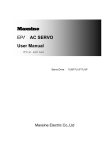
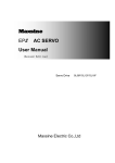
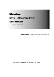
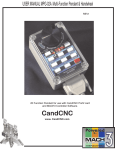
Vital CNC Control
(HiCON Integra pn7766)
CNC Control for
Milling, Lathe, Plasma
Machines
User Guide
Document Revision 1.1
(Updated July 26, 2014)
© 2014 Vital Systems Inc
Phoenix, AZ USA
For more information please visit the product web page:
http://www.vitalsystem.com/cnc
Vital CNC Control User Guide
Table of Contents
License Agreement........................................................................................................................................ 2
I. Introduction ............................................................................................................................................... 3
Package Contents...................................................................................................................................... 3
II. Setup ......................................................................................................................................................... 4
Setting up the Vital CNC Control ............................................................................................................... 4
Integrating the Vital CNC Control with your machine .............................................................................. 6
Internal Layout ...................................................................................................................................... 6
Digital I/O Signals .................................................................................................................................. 7
Drive Connection with Maxsine AC Servo Drives and 7736 Board ....................................................... 8
Drive Connection Without Using the 7736 Board ................................................................................ 9
Mach3 and Software Setup..................................................................................................................... 10
Configuring the Default Profile ........................................................................................................... 10
Creating your own Mach3 profile ....................................................................................................... 14
III. Operation ............................................................................................................................................... 17
Front Panel Controls ............................................................................................................................... 17
MPG Handwheel ..................................................................................................................................... 19
TroubleShooting.......................................................................................................................................... 20
© 2014 Vital Systems, Inc.
1
www.vitalsystem.com
Vital CNC Control User Guide
License Agreement
Before using the Vital CNC Control and any accompanying software tools, please take a moment to
review this License agreement. Any use of this hardware and software indicate your acceptance to this
agreement.
It is the nature of all machine tools that they are dangerous devices. In order to be permitted to use the
Vital CNC Control on any machine you must agree to the following license:
I agree that no-one other than the owner of this machine, will, under any circumstances be responsible,
for the operation, safety, and use of this machine. I agree there is no situation under which I would
consider Vital Systems, or any of its distributors to be responsible for any losses, damages, or other
misfortunes suffered through the use of the Vital CNC Control and its software. I understand that the
Vital CNC Control is very complex, and though the engineers make every effort to achieve a bug free
environment, that I will hold no-one other than myself responsible for mistakes, errors, material loss,
personal damages, secondary damages, faults or errors of any kind, caused by any circumstance, any
bugs, or any undesired response by the board and its software while running my machine or device.
I fully accept all responsibility for the operation of this machine while under the control of the Vital CNC
Control, and for its operation by others who may use the machine. It is my responsibility to warn any
others who may operate any device under the control of the Vital CNC Control of the limitations so
imposed.
I fully accept the above statements, and I will comply at all times with standard operating procedures
and safety requirements pertinent to my area or country, and will endeavor to ensure the safety of all
operators, as well as anyone near or in the area of my machine.
WARNING: Machines in motion can be extremely dangerous!
It is the responsibility of the user to design effective error
handling and safety protection as part of the system. VITAL
Systems shall not be liable or responsible for any incidental or
consequential damages. By using the Vital CNC Control, you
agree to the license agreement.
© 2014 Vital Systems, Inc.
2
www.vitalsystem.com
Vital CNC Control User Guide
I. Introduction
Package Contents
Before proceeding to setup your Vital CNC Control, please take a moment to verify that all necessary
components are present within the delivery.
The Vital CNC Control Package should contain the following items:
-
Vital CNC Control
Power Cable
Vital CNC Control Stand (optional)
MPG handwheel (optional)
Operator’s Keys
Backup Software disc (Windows 7)
NOTE: The Vital CNC Control may contain either the HiCON Integra (pn7766) or DSPMC (pn7762)
motion controller depending on the purchase.
Power cable
Vital CNC Control
with optional stand
© 2014 Vital Systems, Inc.
MPG Handwheel
(Optional)
3
www.vitalsystem.com
Vital CNC Control User Guide
II. Setup
IMPORTANT: Before powering up the unit, make sure that all
packing material is properly removed from the inside of the
Vital CNC Control unit.
Setting up the Vital CNC Control
NOTE: It is recommended to mount your Vital CNC Control or assemble the optional stand before
proceeding with the setup phase.
1. Plug in the power cable to the Vital CNC Control and connect the other end to an outlet. If you
intend setup any wiring, such as inputs, it is recommended that you keep the power switch at
“0”.
© 2014 Vital Systems, Inc.
4
www.vitalsystem.com
Vital CNC Control User Guide
2. Your Vital CNC Control should now be operational and can be turned on with the ON/OFF
Button. The next steps will cover integrating the Vital CNC Control with your machine. During
this phase, the unit must be turned off and unpowered.
Unit is ON
© 2014 Vital Systems, Inc.
5
www.vitalsystem.com
Vital CNC Control User Guide
Integrating the Vital CNC Control with your machine
For these next steps, you will need to open your Vital CNC Control to inspect the internal components.
Internal Layout
Below is an image of the contents of the Vital CNC Control. Please use this image as reference while
continuing with the next setup procedures.
NOTE: Some Vital CNC Controls may contain different parts as requested by the user before shipping.
© 2014 Vital Systems, Inc.
6
www.vitalsystem.com
Vital CNC Control User Guide
Digital I/O Signals
NOTE: Please verify the model of your 7535 Digital I/O Breakout Board before continuing as they can
be provided in PNP (7535P) and NPN (7535N) versions.
Wire the required Digital I/O signals of your machine to the provided Digital I/O Breakout Board. This
breakout board controls the whole Port12 in Mach3 (16 Inputs, 8 Outputs) and allows the use of 24V
one these I/O. Detailed Wiring instructions for PNP and NPN versions can be found in their respective
sections
See “Internal Layout” section for location of the I/O Breakout Board.
PNP Digital I/O Wiring
NPN Digital I/O Wiring
NOTE: You must also wire your 3phase contactor supplying power to
your Servo Drives to the Estop button
contact located inside the Vital CNC
Control to achieve a true hardware EStop.
The Red Disarm Button located on your MPG
Handwheel (if you have purchased it) only
disarms the motion controller.
© 2014 Vital Systems, Inc.
7
www.vitalsystem.com
Vital CNC Control User Guide
Drive Connection with Maxsine AC Servo Drives and 7736 Board
AC Servo Motor and Drive Packages purchased from the Vital Systems website come with additional
components, for a simple and quick plug-and-play wiring setup.
Said components are:
- 1x Drive Interface Board (EPx-DIB) plugs on the servo drive
- 1x Blue RJ45 Drive cable
- 1x Green RJ45 Encoder cable
- 7736 Differential Encoder and StepGen Board
NOTE: the 7736 board works with both DSPMC and HiCON Integra motion controllers. However, this is
only used for the Step/Dir Outputs with the DSPMC.
Setting up the drive connection is simply a matter of plugging the colored cables to the corresponding
colored and labeled RJ45 Ports on the 7736 board and the Drive Interface Board.
The Blue RJ45 cables connect to the drive ports while the green cables connect to the encoder ports.
WARNING: NEVER interchange the Blue Drive cables with the
Green Encoder cables. Doing so may damage your drives and the
Vital CNC Control.
Connection on 7736 Differential Encoder and StepGen
Board
NOTE: You may also view a video tutorial for this
connection method.
link: http://www.youtube.com/watch?v=xDHRH0ZVeow
© 2014 Vital Systems, Inc.
8
Connection on Maxsine AC Servo Drives
www.vitalsystem.com
Vital CNC Control User Guide
Drive Connection Without Using the 7736 Board
This method is used in case the 7736 Board is not installed or interfacing with non-Maxsine AC Servo
Drives.
NOTE: With this method, it is highly recommended to read the User Guide for the HiCON Integra
Ethernet Motion Controller. Encoders 3 through 7 are only accessible via the 7736 Differential encoder
and StepGen Board
NOTE: The 7736 Board uses RJ45 ports for Encoders. For wiring differential quadrature encoders to the
7736 Differential Encoder and StepGen Board, please refer to the 7736 Wiring Guide.
© 2014 Vital Systems, Inc.
9
www.vitalsystem.com
Vital CNC Control User Guide
Mach3 and Software Setup
Configuring the Default Profile
After the digital I/O and the drives have been properly wired, it is now time to switch ON your Vital CNC
Control.
NOTE: Your Vital CNC Control may be password protected on the windows log in. The default
password is “CNC”. It is recommended that the user change this to their own password.
NOTE: Although the purchase of a Vital CNC Control along with Maxsine Motors and Drives allows
Vital Systems to make several configurations within the factory, Digital I/O will have to be wired
manually and configured by the user to suit the target machine.
For a more detailed guide on using HiCON with Mach3, please refer to the Mach3 Software
Integration Manual for HiCON.
Open Mach3 using the default profile provided. You should then see this window popup at the start of
Mach3. Select M3HiCON as shown in the picture.
A message like the one below should appear in the Mach3 Status Bar indicating that communication has
been established between Mach3 and the HiCON.
© 2014 Vital Systems, Inc.
10
www.vitalsystem.com
Vital CNC Control User Guide
Digital I/O can be configured by going to the Ports and Pins Menu, then the “Input Signals” and Output
Signals tab.
Digital I/O Signals wired on the 7535 Breakout board inside the motion controller, can be accessed from
Port 12 for the Mach3 Ports and Pins Config.
Digital I/O Signals connected directly on the HiCON Integra can be accessed from Port 11 for the Mach3
Ports and Pins Config.
The image below shows an example for X Home and Limit switches connected to the HiCON Integra and
the Y homing and limit switches connected on the 7535 I/O Board.
© 2014 Vital Systems, Inc.
11
www.vitalsystem.com
Vital CNC Control User Guide
You can monitor the current I/O states and other status information via the “Status Window”.
© 2014 Vital Systems, Inc.
12
www.vitalsystem.com
Vital CNC Control User Guide
The I/O mapping can also be checked from the Mach3 Diagnostic Tab.
If the Mach3 signals do not correctly activate in response to the state of the Digital Input, then you may
need to check the “Status Window” to see if the Digital I/O state works (or is wired) correctly. If the
signal polarity is incorrect, the active low setting can be changed in the Ports and Pins Config.
© 2014 Vital Systems, Inc.
13
www.vitalsystem.com
Vital CNC Control User Guide
Creating your own Mach3 profile
Should you want to create your own Mach3 profile, you would need to perform these steps to get your
profile working correctly with the Vital CNC Control.
NOTE: This method requires a better understanding of Mach3, as well as experience with the HiCON or
DSPMC plugin config. It is always recommended to use one of the default profiles.
Open the Mach3 application which can be found in C:\Mach3\Mach3.exe. The profile selection screen
will show up when you open Mach3.
1. Click on Create Profile
2. Type a new profile name. You can either
start with default profile values or clone an
existing profile.
4. You may also create a shortcut to your
new profile by creating a shortcut of the
“Mach3.exe” file then right-click to
“Properties”
3. Your new profile should now be useable.
© 2014 Vital Systems, Inc.
14
www.vitalsystem.com
Vital CNC Control User Guide
After creating your own profile, you must perform these additional steps.
1. Copy the macropump.m1s file from the macros folder of any default profile
(Mach3\macros\<profile>\macropump.m1s) and paste it into the macros folder of your new
profile(Mach3\macros\<yourNewProfile>\macropump.m1s).
2. After Mach3 is opened. Go to the general config to enable the macropump.
© 2014 Vital Systems, Inc.
15
www.vitalsystem.com
Vital CNC Control User Guide
3. Enable the “Vital CNC Control” brain and the “MPG Buttons
Selector” brain (if using MPG). To do this, go to “Brain
Control” from the “Operator” menu in Mach3.
© 2014 Vital Systems, Inc.
16
www.vitalsystem.com
Vital CNC Control User Guide
III. Operation
Front Panel Controls
Control
1. Operator
Keyslot
2. CPU LED
Function
Wiring Location
Enables the use of motion control or system enable.
Integra:
[P11, Input 14]
Indicates the current status of the internal motion controller.
Integra:
[P11, Output 6]
If the HiCON motion controller is used, a heartbeat blink pattern
indicates that the motion controller is operational. This LED will
turn off during firmware upgrade by the user.
3. Estop Button
Disarms the current system and stops all motion. The button can be Integra:
twisted clockwise after being pressed to remove the system from [P11, Input 9]
the Estop state.
4. Error LED
Turns on when the internal motion controller incurs an error.
5. User
Programmable
Function
Buttons
These buttons are wired to specific inputs on the HiCON and can be Integra:
mapped to execute custom commands or macros in Mach3.
FN1 – [P11, Input 12]
FN2 – [P11, Input 11]
FN3 – [P11, Input 10]
6. Enable Button
Enables/Arms the system. Motion can only be performed if the Integra: [P11, Input 8]
system is armed. Glows orange to indicate that the system is armed
and ready for motion.
7. Feedrate
Override
Overrides the current feedrate to speed up or slow down the Integra:
execution of a gCode file in Mach. Range varies from 0% (left) to Analog Input 0
250% (right).
© 2014 Vital Systems, Inc.
17
Integra:
[P11, Output 7]
www.vitalsystem.com
Vital CNC Control User Guide
8. ON/OFF Button
Turns ON the Vital CNC Control if pressed. Turns OFF the Vital CNC
Control if held while the unit is currently ON. The power sign glows
blue to indicate that the Vital CNC Control is turned on.
9. Spindle RPM
Override
Overrides the current Spindle RPM. Range varies from 0% (left) to Integra:
250% (right).
Analog Input 1
10. Cycle Start
Button
Initiates the execution of the current GCode File in Mach.
Integra:
[P11, Input 15]
11. Cycle Stop
Button
Stops the execution of the Current GCode File in Mach.
Integra:
[P11, Input 13]
© 2014 Vital Systems, Inc.
18
www.vitalsystem.com
Vital CNC Control User Guide
MPG Handwheel
If you have purchased an MPG Handwheel from Vital Systems Inc., you can simply plug the Handwheel
into the Port J10 on the HiCON Integra. Provided that one of the factory-default Mach3 profiles is used,
the MPG should be useable without any need for I/O configuration.
© 2014 Vital Systems, Inc.
19
www.vitalsystem.com
Vital CNC Control User Guide
TroubleShooting
My unit is powered up and the CPU LED is blinking, but the Digital I/O do not physically turn
ON/OFF correctly.
-
Check the 24V Power Supply and see if the red LED is
turned on. If not, check the fuse close to it. If it is blown,
then the 24V are not supplied to the HiCON Integra. 24V
are required for Digital Inputs and Outputs.
I have plugged My MPG Handwheel into Port J10 on the HiCON motion Controller, but it is not
functioning.
-
Make sure that the “MPG_Buttons_Selector” brain is enabled for the current Mach3 profile.
I can’t enable/arm my Vital CNC Control.
-
Make sure that the operator keys are inserted into the keyslot on the front panel and turned
clockwise. Check the error LED on the front panel if it is lit up. This could mean that one of the
Estop Buttons is currently triggered. Estop buttons are sticky switches and will need to be
rotated clockwise to deactivate.
I have wired my drives, but I can’t get any motion.
-
-
Make sure that the axes are properly configured within the plugin config.
o Set the Output Type to “Stepper”.
o Set the Output Index to the correct channel.
o Set the Control Input Source to “Machxx”.
Ensure the drive enable signal (Enable1) is mapped to the correct output in the Ports and Pins
Config.
Check that the Axes are enabled in the Ports and Pins config (“Motor Outputs” tab).
Directions on doing these can be found in the HiCON Software Integration Manual for Mach3.
For more information, visit vitalsystem.com or email us at [email protected].
© 2014 Vital Systems, Inc.
20
www.vitalsystem.com