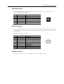
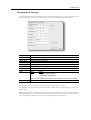
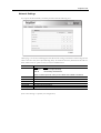
1
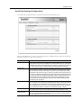
User Manual
Anybus Serial Server
®
Rev. 1.20:1
HMS Industrial Networks AB
Germany + 49 - 721 - 96472 - 0
Japan
+ 81 - 45 - 478 -5340
Sweden
+ 46 - 35 - 17 29 20
U.S.A
+ 1 - 773 - 404 - 3486
UK
+ 44 (0) 1908 - 359301
[email protected]
[email protected]
[email protected]
[email protected]
[email protected]
Table of Contents
Table of Contents
Preface
About This Document
How To Use This Document ............................................................................................................ P-1
Important User Information .............................................................................................................. P-1
Related Documents.............................................................................................................................. P-2
Document History ............................................................................................................................... P-2
Conventions & Terminology.............................................................................................................. P-3
Support .................................................................................................................................................. P-3
Chapter 1
About the Anybus Serial Server
General....................................................................................................................................................1-1
Mounting ................................................................................................................................................1-2
Mac ID & Default IP Address ............................................................................................................1-2
Connectors .............................................................................................................................................1-3
Overview .......................................................................................................................................1-3
Power Supply ................................................................................................................................1-3
EIA-485 Interface .......................................................................................................................1-4
EIA-232 Interface .......................................................................................................................1-4
Ethernet Interface..........................................................................................................................1-4
Indicators................................................................................................................................................1-5
Chapter 2
Configuration
IP Address ..............................................................................................................................................2-1
About the Anybus IPconfig Utility ...............................................................................................2-1
Scanning for Connected Devices .....................................................................................................2-1
Changing the IP Settings...............................................................................................................2-2
Installing the Windows Driver (Serial/IP) ........................................................................................2-3
General Information......................................................................................................................2-3
Log In ..........................................................................................................................................2-3
Welcome Page ...............................................................................................................................2-3
Network Settings ..........................................................................................................................2-4
Serial Port Settings (Configuration)...............................................................................................2-5
Password Settings..........................................................................................................................2-6
Appendix A Technical Specification
Preface
About This Document
How To Use This Document
This document contains a general introduction as well as a description of the technical features provided by the Anybus Serial Server, including the PC-based configuration software.
The reader of this document is expected to be familiar with communication systems in general and the
Microsoft Windows operating system.
Important User Information
The data and illustrations found in this document are not binding. We, HMS Industrial Networks AB,
reserve the right to modify our products in line with our policy of continuous product development. The
information in this document is subject to change without notice and should not be considered as a commitment by HMS Industrial Networks AB. HMS Industrial Networks AB assumes no responsibility for
any errors that may appear in this document.
There are many applications of this product. Those responsible for the use of this device must ensure
that all the necessary steps have been taken to verify that the application meets all performance and safety requirements including any applicable laws, regulations, codes, and standards.
Anybus® is a registered trademark of HMS Industrial Networks AB. All other trademarks are the property of their respective holders.
The examples and illustrations in this document are included solely for illustrative purposes. Because of
the many variables and requirements associated with any particular implementation, HMS Industrial
Networks cannot assume responsibility or liability for actual use based on these examples and illustrations.
Warning:
This is a class A product. In a domestic environment this product may cause radio interference in which case the user may be required to take adequate measures.
ESD Note:
This product contains ESD (Electrostatic Discharge) sensitive parts that may be damaged
if ESD control procedures are not followed. Static control precautions are required when
handling the product. Failure to observe this may cause damage to the product.
About This Document P-2
Related Documents
Document name
-
Author
-
Document History
Summary of Recent Changes (v1.20... v1.20:1)
Change
Changed layout
Misc. minor changes
Page(s)
-
Revision List
Revision
1.00
1.10
1.20
1.20:1
Date
03-03-02
05-11-01
06-06-30
06-11-17
Author(s)
JOAK
HACA
MASA
PeP
Chapter(s)
-
Description
First released version
Update for Modbus support etc.
Update to new design structure
Updated layout + misc. minor changes
About This Document P-3
Conventions & Terminology
The following conventions are used throughout this document:
•
Numbered lists provide sequential steps
•
Bulleted lists provide information, not procedural steps
•
The term ‘Serial Server’ is refers to the Anybus Serial Server
•
EIA-485 is also commonly referred to as RS-485
•
EIA-232 is also commonly referred to as RS-232
Support
HMS Sweden (Head Office)
E-mail:
Phone:
Fax:
Online:
[email protected]
+46 (0) 35 - 17 29 20
+46 (0) 35 - 17 29 09
www.anybus.com
HMS America
E-mail:
Phone:
Toll Free:
Fax:
Online:
[email protected]
+1-773-404-2271
888-8-Anybus
+1-773-404-1797
www.anybus.com
HMS Germany
E-mail:
Phone:
Fax:
Online:
[email protected]
+49-721-96472-0
+49-721-964-7210
www.anybus.com
HMS Japan
E-mail:
Phone:
Fax:
Online:
[email protected]
+81-45-478-5340
+81-45-476-0315
www.anybus.com
Chapter 1
About the Anybus Serial Server
General
A serial server is a device that forwards data between a serial port and an Ethernet network. It can be
used to connect your serial devices to a LAN or Internet without any hardware modifications. Together
with a special software driver in a PC, it can be used as a remote serial port.
PC applications designed to access devices on a normal serial port, can access the remote serial server
without any software modifications. The LAN/Internet network together with the serial server and driver can be viewed as a long “virtual” serial cable
6HULDO'HYLFH
6HULDO'HYLFH
(,$
6HULDO'HYLFH
(,$
(WKHUQHW
$Q\EXV6HULDO6HUYHU
&RPSXWHUZLWK6HULDO,3VRIWZDUH
6HULDO'HYLFH
6HULDO'HYLFH
The Anybus Serial Server connects serial devices to Ethernet networks using the IP protocol family.
Some different types of serial devices supported are listed below:
•
Scanners
•
Printers
•
PLC’s
•
Data Collection Devices
•
Telecommunications Equipment
•
Data Display Devices
•
Security Alarms and Access Control Devices
•
Hand-held Instruments
•
Modems
About the Anybus Serial Server 1-2
Mounting
A: Snap On
B: Snap Off
Procedure
1. Snap the Serial Server on to the DIN-rail (as described on pictures above).
2. Connect the Ethernet cable to the RJ45 connector.
3. Connect the serial device to the 9-pole DSUB connector.
4. Connect the Power Supply and apply power.
5. Now you can start using the Serial Server.
(use the Anybus IPconfig Utility to configure the IP address and other network settings).
See also...
•
2-1 “IP Address”
Mac ID & Default IP Address
The default IP address of the Serial Server is 10.200.1.X, where X is the last number of the MAC ID
(Can be found on the label on the device, displayed in HEX format).
0DF,'
See also...
•
2-1 “IP Address”
About the Anybus Serial Server 1-3
Connectors
Overview
#
1
2
3
4
Description
Power Supply
EIA-485 Interface
EIA-232 Interface
Ethernet Interface
Comments
See 1-3 “Power Supply”
See 1-4 “EIA-485 Interface”
See 1-4 “EIA-232 Interface”
See 1-4 “Ethernet Interface”
Power Supply
#
24
23
22
21
20
19
18
17
Signal
Vin+
VinDigital in 2+
Digital in 2Digital in 1+
Digital in 1-
Comments
Voltage Range: 9... 32VAC/DC
(Ground connection)
(not used)
Digital in 1- and Digital in 2- are internally tied together.
See also...
•
A-1 “Technical Specification” (Power Supply Requirements)
About the Anybus Serial Server 1-4
EIA-485 Interface
The 6-pole RJ-12 connector features an EIA-485 interface. This port can be used to connect to any
equipment with an EIA-485 interface.
#
1
2
3
4
5
6
Signal
A
B
Common
Common
-
Comments
A-Line
B-Line
Signal ground
Signal ground
(not used)
(not used)
EIA-232 Interface
The 9-pole DSUB, male connector on the Serial Server features a fully equipped EIA-232 interface. This
port can be used to connect to any equipment with an EIA-232 interface. The Serial Server is configured
as a DTE device.
The following signals are available:
#
1
2
3
4
5
6
7
8
9
Signal
CD
Rx
Tx
DTR
GND
DSR
RTS
CTS
RI
Comments
Carrier Detect
Receive
Transmit
DTE Ready
Signal ground
DCE Ready
Request To Send
Clear To Send
Ring Indicator
Ethernet Interface
The Ethernet interface supports 10/100Mbps, using a standard RJ45 connector.
PDOH
About the Anybus Serial Server 1-5
Indicators
6WDWXV
6HULDO/LQN
$FWLYLW\
/LQN
LED
Module Status
Serial Link Status
LAN Activity
Link 10/100
State
Off
Green
Orange
Green, flashing
Red, flashing
Orange
Green, flashing
Red, flashing
Off
Green
Orange
Function
No power
Module is running in normal mode
During boot-up
Serial Packet receive (on either port)
Serial Packet transmit (on either port)
During boot-up
Ethernet Packet received
Ethernet Collision detected
No Ethernet Link detected
Ethernet network detected, 10Mbps
Ethernet network detected, 100Mbps
Chapter 2
Configuration
IP Address
About the Anybus IPconfig Utility
The Anybus IPconfig utility is a PC-based configuration utility used to set TCP/IP network settings in
the Serial Server. This utility has the ability to scan the Ethernet network for connected Anybus products
and let the user set IP-address, net mask, gateway, DNS and hostname for each device.
Installation
•
System Requirements
- 133MHz CPU (or higher)
- 5Mb of free hard disk space
- Microsoft Windows 95/98/ME/NT/2000/XP
- Network Interface (Ethernet)
•
Installation Procedure
There are two methods to install the Anybus IPconfig utility, either downloading it from the
HMS website or use the installation CD ROM.
- Using the CD ROM: Run “Setup-AnybusIPconfig.exe” and follow the on-screen instructions.
- From website: Download the self-extracting installation package “Setup-AnybusIPconfig.exe” from www.anybus.com and run it.
Scanning for Connected Devices
When the Anybus IPconfig utility is started, it will
scan the Ethernet network for Anybus products. All
detected devices will be presented in a list in the main
window. To alter the settings for a device, double click
on its’ entry in the list.
If you want to force a new scan for devices, you can
press the “Scan” button.
Column
IP
SN
GW
DHCP
Version
Type
MAC
Contents
The IP address
The subnet mask
The default gateway
Dynamically assigned IP address On/Off
The version of the application-software
The product type
The MAC address of the Serial Server
See also...
•
1-2 “Mac ID & Default IP Address”
Comments
Printed on a label on the device in HEX format
Configuration 2-2
Changing the IP Settings
To change the IP settings on a detected device, double-click on the device you want to configure in the
list of devices. This will open up a dialog where you can enter the desired IP configuration.
Field
IP Address
Subnet mask
Default gateway
Primary DNS
Secondary DNS
Hostname
Password
New Password
DHCP
Change Password
Contents
The IP address of the Serial Server
Mask network
The default gateway in the network
The primary Domain Name Server
The primary Secondary Name Server (if it exists)
Here you can enter a hostname of your device.
The default password for authentication of the new settings is ‘admin’.
To change the password, first check the ‘Change password’ checkbox.
Meaning:
Setting:
On
Use server-assigned IP settings.
Off
Use the settings described below.
Note: Do not select the DHCP option unless you have a DHCP server available on the network.
Check this checkbox to enable the ‘New password’-field
(Pressing ‘Set’ will cause the Serial Server to reboot and apply the new settings).
To obtain the necessary information about IP address, subnet mask etc. please contact your network
administrator.
Note: You can test the new settings by opening a web-browser and enter the IP you just selected. If you
selected DHCP and want to know what IP your device have been assigned, you can do a new scan with
the Anybus IPconfig utility to view the new network configuration information.
Configuration 2-3
Installing the Windows Driver (Serial/IP)
General Information
To be able to use the Serial Server you need to install the Serial/IP driver on a PC. For installation instructions, consult the “Serial/IP Quick Start” available at the HMS website (‘www.anybus.com’).
Log In
Open a web browser (e.g. Internet Explorer) and enter the IP address you have set on the Serial Server
unit with the Anybus IPconfig utility.
Example:
If you entered the address 10.10.10.83 then you should enter the text below in the address field
of the browser and press enter:
http://10.10.10.83
Now you should see the login screen (see figure). To be able to configure the serial server
you should enter “admin” in the user name
box. The default password is “admin”. You
can later change the default password to something else. This will be described later in the
section “Admin”.
Note: If you have problems to log in and you
are sure that your password is correct, make
sure that Caps Lock is not enabled on your
keyboard.
Welcome Page
The welcome page of the Serial Server.
Configuration 2-4
Network Settings
If you press the Network link you will be presented with the following view.
On this page you can view and change the TCP/IP network settings in the device. These settings are the
same as the ones set by the Anybus IPconfig utility. To obtain the necessary information about IP address, Subnet mask etc. please contact your network administrator.
Field
DHCP
Host Name
IP Address
Netmask
Gateway
Primary DNS
Secondary DNS
Details
Setting:
Dynamic IP
Static IP
Meaning:
Use server-assigned IP settings.
Use the settings described below.
Note: Do not select ‘Dynamic IP’ unless you have a DHCP server available on the network.
Here you can enter a hostname of your device.
The IP address.
The subnet mask
The default gateway
The primary Domain Name Server
The primary Secondary Name Server (if it exists)
(Press “Save Settings” to update your configuration).
Configuration 2-5
Serial Port Settings (Configuration)
If you press the Configuration link you will be presented with the following view.
The page is divided in two sections, one for each serial port. All fields exist for both ports except that
the EIA-485 port has no flow control selection.
Field
Serial Port Number
Modbus Mode
Manual Serial Settings
Baudratea
Character Formata
Description
The Serial Server answers on incoming connections on this IP port number. The defaults are
2000 for EIA-232 port and 2001 for EIA-485 port. Use these numbers when you connect from
the Serial/IP driver, telnet or other application that can connect to a socket port. For example, if
you connect to IP port 2000 your communication will go through the EIA-232 serial port.
This is regarding fragmentation on received messages on the serial port. If On, it makes the
low level serial driver to wait 3.5 characters (standard Modbus message break time) before it
passes the received characters further. Then it may be sent in one TCP/IP packet to prevent
fragmentation on the receive side. The 3.5 char time is calculated from the current baud rate. If
Off, you still can select the time in milliseconds to wait in silence before the received characters
is passed to the serial server application in the NetBiter. Typically, 0 disables this feature. If so,
characters received in about 10 milliseconds will be sent in each TCP/IP packet. This may
mean less delay for each received byte, but may mean more TCP/IP overhead and maybe
fragmentation of the serial packet.
If you want to lock the settings on the serial port, check this box. This is useful for various reasons. For example, if you connect with some application that doesn’t do the remote serial port
setup. Normally your PC serial application does this through the Serial/IP driver when you connect to a Serial/IP driver Com port. If you use a program that doesn’t set up the remote serial
port, the Serial Server defaults to: 19200 baud rate, 8 data bits, No parity, 1 stop bit.
Sets the communication rate on the serial port.
Valid settings are 300, 600, 1200, 2400, 4800, 9600, 19200, 38400, 57600 and 115200.
First field is how many bits are used for each character. You can set 7 or 8 data bits. Second
field is for parity configuration. Choose between No, Even or Odd parity. The third field is for
how many stop bits to use. There can be 1 or 2.
Configuration 2-6
Field
a
Flow Control
Description
For the EIA-232 port you can select if you want flow control handled by the UART. If this is
selected then transmit is automatically stopped/continued when serial buffer is full/available.
You can choose between NONE, CTS/RTS and XON/XOFF. NONE disables UART flow control. If CTS/RTS is selected the two UARTs involved uses two dedicated wires in the serial
cable to control flow. The Serial Server uses RTS when it wants to transmit and gets CTS back
when it is clear to send. Be sure to use a serial cable with these wires connected. If XON/XOFF
is used the remote UART should send characters to signal its buffer state.
a. This setting is available only if the ‘Manual Serial Settings’-checkbox has been checked.
Press “Save” to update your configuration. You will be asked to press a reboot button in the next view.
After about 20 seconds has passed you can press the start menu field up in the right corner to take you
back to the start page.
Note: The Server Port Number must match the value entered in the Serial/IP Driver.
Password Settings
If you press the Admin link you will be presented with the following view.
This screen allows you to change the administrator password for this device. Enter the new password
in the Password box and in the Confirm Password box. Click “Save Password” to change the password.
Appendix A
Technical Specification
Ethernet Interface
•
10Base-T or 100Base-TX (IEEE 802.3)
•
RJ45 Connector
Serial Interface (EIA-232)
•
EIA-232 with full modem control (RTS,CTS,DCD,DTR,DSR,RI)
•
300... 115.200bps operation
•
9-pole DSUB connector
Power Supply Requirements
•
9... 32 VAC/DC
•
1.7W
Temperature Range
•
0... 55 °C (Operating)
•
-25... 75 °C (Non-operating)
Humidity
•
5... 93% RH, non-condensing
Housing Material
•
Grey plastic (LEXAN 940)
•
Self-extinguishing according to UL94-V0
Mounting Option
•
DIN-rail (EN50022)
CE Certification
•
According to EN 50 081-2:1993 and EN 61000-6-2:1999