1
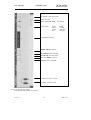
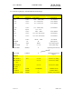
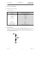
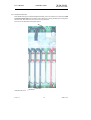
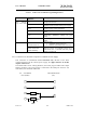
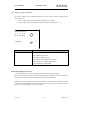
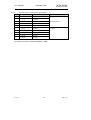
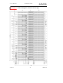
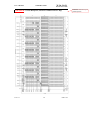
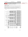
Series 6000 LHC
VME -64x
User’s Manual
*00571.A3
General Remarks
The only purpose of this manual is a description of the product. It must not be interpreted as
a declaration of conformity for this product including the product and software.
W-Ie-Ne-R revises this product and manual without notice. Differences of the description in
manual and product are possible.
W-Ie-Ne-R excludes completely any liability for loss of profits, loss of business, loss of use
or data, interrupt of business, or for indirect, special incidental, or consequential damages of
any kind, even if W-Ie-Ne-R has been advises of the possibility of such damages arising
from any defect or error in this manual or product.
Any use of the product which may influence health of human beings requires the express
written permission of W-Ie-Ne-R.
Products mentioned in this manual are mentioned for identification purposes only. Product
names appearing in this manual may or may not be registered trademarks or copyrights of
their respective companies.
No part of this product, including the product and the software may be reproduced,
transmitted, transcribed, stored in a retrieval system, or translated into any language in any
form by any means with the express written permission of W-Ie-Ne-R.
Terms
The Terms “Crate” and “Subrack” are used interchangeable in this document
Mains Voltage and Connection
The Power supplies are equipped with a “World”- mains input, which works properly form
94VAC up to 264VAC and within a frequency range of 47 to 63Hz. Before connecting to the
mains please double-check correspondence.
Mains input connection at the power supply side is done with a 3-pin “Hirschmann” 16Aconnector or power terminals. This input is approved for max. 16 A current. An adequate
16A external fusing per power box has to be installed at user side.
Hirschmann.
Signal
Description
Color of the Wire
Pin 1
L
Phase
black or brown
Pin 2
N
Return, Neutral
blue
Pin 3
Earth
21.01.13
not connected
PE
Protective Earth
i
green/yellow
*00571.A3
Safety
After connecting the Power box to the mains, the mains input module is powered
permanently. Filter and storage capacitors of the power factor correction module are charged
with about 400VDC. The DC-On-Signal as well as a power switch at control board (if any
installed) operates as a DC on/off switch only and not as a mains breaker. Therefore it
becomes dangerous if the box cover is open. In this case a lot of components on high
voltage potential get touchable!
Before starting any kind of work inside the power box remove the unit from
mains and wait a couple of minutes with your activities! Discharge the primary
DC Filter-capacitors by use of a well isolated 22 ohm 10W resistor.
We recommend in case of any male function to send the power box to Wiener or
to one of our representative for service
Grounding Stud
Each VME- bin is outfitted with a grounding stud which has to be wired to mains
earth or zero potential line according to CERN’s rule / law.
The stud is situated at the right side panel behind the fan space (rear view).
21.01.13
ii
*00571.A3
Declaration of Conformity
Art. 10.2 of 89/336 and 89/392 / ECC
W-Ie-Ne-R
Plein & Baus GmbH
declare under our own responsibility that the product
VME / 6021Crate
Items: 0B0x.xxxx, 0F0x.xxxx, 0P0x.xxxx
to which this declaration relates, is in conformity with the following standards or normative documents :
1.
EN 50 081 - 1
2.
EN 61 000 3 - 2
3.
EN 50 082 - 1
4.
EN 60 950
Conditions:
This crate is not a final product. The use after installation and powered modules inside needs possibly
additional screenings to be in conformity of the definition.
Admitted for powering by all mains.
Name and signature of authorized person
Place and Date
Name und Unterschrift des Befugten
Ort und Datum
Juergen Baus
Techn. Director
21.01.13
Febr. 2000
iii
*00571.A3
Table of contents:
1
General Information......................................................................................................... 6
1.1 6021 Subracks / Crates .............................................................................................. 6
1.1.1 6021 Crate with Remote Power Supplies............................................................. 6
1.1.2 6021 Crate with Local Power Supplies................................................................ 6
1.2 6020 Fan Trays........................................................................................................... 7
1.3 6021 Power Supplies .................................................................................................. 7
1.4 Remote Monitoring and control (Slow control) ...................................................... 8
1.4.1 CAN (Controller Area Network) ......................................................................... 8
1.4.2 OPC access........................................................................................................... 8
2
Operation, Function and Connections.............................................................................. 9
2.1 Fan Tray Operation and Control ............................................................................. 9
2.1.1 Function of Fan Tray Switches .......................................................................... 10
2.1.2 Additional temperature sensors.......................................................................... 10
2.1.3 Information by Fan Tray LED’s ........................................................................ 11
2.1.4 Hot Swapping of LX Fan Tray .......................................................................... 11
2.1.5 Programming of Fan tray ................................................................................... 12
2.1.6 LX fan-tray UEL 6020 Front panel with CANbus Connectors ........................ 13
2.1.7 Monitoring Display: Standard Measurement Ranges ........................................ 14
2.2 6021- Bin Technical details...................................................................................... 15
2.2.1 VME 64x Bus Current Ratings .......................................................................... 15
2.3 Bus Termination....................................................................................................... 15
2.3.1 Ground Connection ............................................................................................ 16
2.3.2 Pin Assignments of VME 64x-Bus..............Fehler! Textmarke nicht definiert.
2.3.3 Power Protection Memory PPM (Plug & Play Logic)....................................... 17
2.4 Power Supply UEP6021 LHC ................................................................................. 18
2.4.1 Power Connector Board (Round Contacts)........................................................ 18
2.4.2 Power connector pin assignments ...................................................................... 18
2.4.3 Sense and Signal Connector-SUB D 37............................................................ 20
2.4.4 Fan tray and Control Connector SUB D9 .......................................................... 20
2.4.5 Plug & Play Logic.............................................................................................. 21
2.4.6 Control and Adjustment of 6021 Power Supply ................................................ 21
2.4.7 Connection of a Personal Computer to UEP6021 Power Supply ...................... 22
2.4.8 Output Voltage Adjustments.............................................................................. 23
2.4.9 Power Supply AC on / off ................................................................................ 23
2.4.10 CANbus Option, Transmission Speed Index ..................................................... 24
APPENDIX A : Technical Details of 6021 Power Supplies for LHC .................................. 25
APPENDIX B : Typical Module Efficiency...................Fehler! Textmarke nicht definiert.
21.01.13
iv
*00571.A3
APPENDIX C : Technical Details of Fan Trays................................................................... 27
Blower efficiency ............................................................ Fehler! Textmarke nicht definiert.
APPENDIX D : VME 64x Backplane, Situation of Power Bugs ......................................... 29
APPENDIX E : Custom Backplane, Situation of additional Power Bugs............................ 30
APPENDIX F : Custom Backplane, Power Bugs detailed ................................................... 31
21.01.13
v
*00571.A3
User’s Manual
VME 6021 CERN
W-Ie–Ne-R
Plein & Baus GmbH
1
General Information
1.1
6021 Subracks / Crates
Different versions are foreseen to fulfill the requirements of the LHC community.
Two formats, 6Ux160mm depth and 9U x 400mm depth are available, both with transition
cages.
9U crates may optionally equipped with a 4slot 6U x 160mm front cage, positioned on slot
1-4, but recessed in respect to the front panels of the 9U modules (connectors all on
backplane level).
The crates are equipped either with 21 slot 64x backplane or with custom designed ones.
Topped on slot 1 a temperature sensor is situated. A second sensor will be delivered with
each subrack for free positioning by the user. The W-Ie-Ne-R VME 64x backplane offers 7
free plugs at the top between different slots, to connect further sensors among slot-1-sensor.
According to IEEE1101.10 the mechanics are equipped with easily replaceable EMC
gaskets
The power requirement of the bin (according to the label sticker) is stored in a bin memory
(Plug & Play). This memory logic compares any connected power supply for compatibility
before enabling power on switch at fan tray front panel.
1.1.1 6021 Crate with Remote Power Supplies
1.1.1.1
Subrack Variant 1 (Remote)
The VME -Crate 6021- Variant 1 consists of a bin UEV 6021 with a 2 U high fan tray space
for a UEL 6020 fan tray. The total height is 2U+modul format (6U or 9U)+1U wiring space
in top of the bin. Totally 12U high for 9U and 9U high for 6U subracks.
Behind this wiring chamber there is a terminal board situated. This bears all power-contacts
(thread-studs) and the sense/control connector, a 37 pin Sub D type for connecting subrack
and remote power supply.
Subracks of Variant 1 have free unimpeded access to backplane rear side for
21 transition modules:
6U subracks features 160mm depth and 6U height, optionally 80mm deep,
9U subracks features 220mm depth and 9U height, optionally 160mm deep
1.1.1.2
Subrack Variant 1a (Remote)
Divergent from variant1 the variant 1a version is equipped with custom backplane(s)
1.1.2 6021 Crate with Local Power Supplies
1.1.2.1
Crate Variant 2 (Local)
The VME -Crate 6021- Variant 2 consists of a bin UEV 6021 with a 2 U high fan tray space
for a UEL 6020 fan tray. The total height is 2U+modul format (6U or 9U). Totally 11U high
for 9U and 8U high for 6U subracks.
The Local Power supply is placed behind the J1 Level. Therefore the access to backplane
rear side is limited to the J2 and J3 (for 9U format) only.
Subracks of Variant 2 have limited access to backplane rear side for
21 transition modules:
6U crates have nothing foreseen, optionally 3U to J2, 160mm or 80mm deep,
9U subracks features 160mm depth and 6U height to J2/J3, optionally 220mm deep
21.01.13
6
*00571.A3
User’s Manual
VME 6021 CERN
W-Ie–Ne-R
Plein & Baus GmbH
1.2
6020 Fan Trays
The-fan trays are plugged into the bin from the front side. For efficient cooling, controlling
and monitoring of the crate various fan trays are constructed according to the slot deepness.
Air entry is from bottom side in general, which gives full cooling efficiency. Fan rotation
speed is shown on the monitoring display and can be regulated. Furthermore temperature of
the air entry and optionally the exhaust above selected slots.
The UEL 6020 fan tray and control unit occupies two units of a 6021 crate below the slots.
To achieve an excellent airflow homogenization through the inserted VME modules, all fan
trays for 400mm modules (and larger ones) are outfitted with a topped plenum chamber
which acts as a pressure volume below the VME modules.
Among the different types high performance super blower with four or six blowers can be
used, too.
All DC voltages (up to 8) at backplane level and the corresponding currents among other are
shown by the alphanumeric monitoring. The threshold-limits (minimum / maximum voltages
and currents) can be set manually or piloted by remote control and remain stored even after
lack of voltage. In case of global trip off, the fault will be displayed by the diagnostic
system.
VME-signals as ACFAIL and SYSRESET are generated according to VME-Specs.
SYSRESET can also be released manually.
1.3
6021 Power Supplies
The VME power supply of the 6000 series is a micro-processor controlled switching power
supply designed in the high density W-Ie -Ne-R - cavity technology, which provides a very
low noise output voltage.
The mains input with power factor correction (PFC) works according to EN 61000-3-2 IEEE 555-2. An external fuse or circuit breaker has to be installed (16A for 3U boxes with
3kW).
The inrush current is limited by a soft start-circuit and not higher as 16A, when the cold unit
has been connected to the mains.
The AC- input module is permanently powered after connecting the unit to the AC- mains.
Any POWER ON/OFF Switch activates only the DC on/off function of the power inverter
modules.
The EN 50 081-1 for generic emissions as well as the EN 50 082-1 or 2 for immunity
standards, in particular EN 55 011 RFI rejection (incl. VDE 0871 class B) and EN 55 022
electromagnetic compatibility is accomplished. The insulation performs the EN 60 950,
ISO 380, VDE 0805 (SELV)! Furthermore are considered UL 1950, UL 1012, UL 478,
C 22.2.950, C 22.2.220/234.
Therefore the UEP 6021 power supplies can fulfill the CE rules comprehensively and can
CE marked for use at all power nets.
Turning on the power supply all voltages reach the nominal values nearly simultaneously
within 50 ± 2.5 ms (start-end-time) whereby the voltage versus time curve shows a
monotonic behavior. The switch-off-time is 5±2.5 ms. within this time the DC outputs are
discharged to 10% of the nominal voltages or less.
The power packs are readily replaceable. The maximum output power is ca. 3000W for a 3U
power box. The available DC output power is in correspondence with the 92... 265VAC
21.01.13
7
*00571.A3
User’s Manual
VME 6021 CERN
W-Ie–Ne-R
Plein & Baus GmbH
input voltage. Also the installed modules urge the efficiency (3,3V module efficiency is
some lower then those of a 48V module).
1.4
Remote Monitoring and control (Slow control)
All local monitoring functions of the crates are also remotely available. In addition, it is
possible to read and change the power supply and fan tray operating parameters (E.g.
Overvoltage, Trip Points,etc.). If fan-relevant parameters are accessed, the power supply
communicates with the fan tray over a crate- internal serial link.
1.4.1 CAN (Controller Area Network)
The power supply has a CAN field bus interface built in. So it is possible to link up to 100
devices with a simple 2-wire connection. The transmission speed, network address and
broadcast address are selectable with the fan tray.
The programming details of the CAN bus can be found in the “CAN-Bus Interface for W-IENE-R Crate Remote Control” (Part No. 00183.A0)
1.4.2 OPC access
A server according to OPC Data Access V2.05 is optional available.
OPC (OLE for Process Control) allows fast and secure access to data and information under
Windows operating systems. As an industry-spanning, multi-vendor software interface, OPC
minimizes connection and maintenance overheads.
This server, running on a Computer with the Microsoft Windows 2000 operating system,
enables access to all power supplies which are connected to the computers CAN network
card(s). It is possible to
•
•
•
•
access from any OPC Client application to the data of one or more servers
encapsulating the properties specific to the server and type of communication
commissioning support due to automatic scanning of the network and registration of
communication stations
restricting access rights by the underlieing Microsoft DCOM.
The details of the OPC server can be found in the “OPC Server for W-IE-NE-R Crate
Remote Control”
21.01.13
8
*00571.A3
User’s Manual
VME 6021 CERN
W-Ie–Ne-R
Plein & Baus GmbH
2
Operation, Function and Connections
2.1
Fan Tray Operation and Control
All monitoring and control operations are performed by a micro-processor based alarm and
control circuit placed inside the UEP 6021 power supply monitored by UEL 6020 fan trays.
The reasons of a trip off will be displayed on the alphanumerical display and monitored via
network (CANbus).
To protect both the power supply and the VME modules, a DC cut-off is started in the
case of:
• overheat:
in the power modules (each module is
equipped with over temperature sensors);
• overcurrent:
if peak currents have been exceeded
(any lower programmed current limit releases
an undervoltage- trip off)
• overvoltage:
if voltage >125% (default, crow bar function)
and if voltage >105% (default, upper Status-level
programmable via fan tray or network)
• undervoltage:
if voltage <97.5% % (default, lower Status- level,
programmable via fan tray or network)
• fan failure:
if one or more fans fail
Voltages, currents, cooling air temperatures, fan speed, power dissipation of inserted
modules, operation time of power supply and fan tray and net parameters can be shown on
the fan-tray display. ADC resolution is 10 bit. The accuracy of the voltage measurement is
better than 0.5%.
The total accuracy of the current measurement depends on the corresponding voltage, i.e. for
±5V it is better than 2A in the range between 5A - 50A and for -2V it is better than 1A in the
range between 1A - 20A. Above these current ranges the accuracy is <5% of the final value.
In the case of ±12V and ±15V the accuracy is better than 0.2A in the whole current range.
21.01.13
9
*00571.A3
User’s Manual
VME 6021 CERN
W-Ie–Ne-R
Plein & Baus GmbH
2.1.1 Function of Fan Tray Switches
POWER ON /Off
1. main switch for ventilation and power supply
2. Reset trip off
MODE SELECT
selection switch to choose items and values for fan-tray and
power supply monitoring and control
SYS RES
protected located switch for VME SYSRESET circuit activation
FAN SPEED
push button for step wise in- or decrease of fan speed.
FAN AUTO OFF
one of two functions, selected by software (see 2.1.5):
1. Switch off after fan-failure (yes/no)
2. Activate the “hot swap” function of the fan
ADDRESS
LOCAL
selects crate address for remote network
permits only data transmitting, no commands receiving
The adjusting range of fan speed is from 1200 RPM up to >3000 RPM. The displayed value
of RPM concerns the average of all blowers inside the fan tray. This average value will
compared with the pre selected reference speed. The display shows the fan speed in flashing
mode if the selected speed is not equal with the true speed. This happens when either the
fans are still accelerated to any other selected turns or the selected value is not reachable.
This could be the case, if
1. more than 3000 RPM are selected and high density modules block the airflow
2. or one ore more blower are slow (bearing problems)
In case of example 2. the FAN FAIL circuit will detect this status as fan fail after a certain
time!
While the display shows average speed of all fans only, the CANbus option will transmit the
turns of each fan tray separated.
2.1.2 Additional temperature sensors
The Slot-1-Sensor and optional installed temperature sensors, measure the temperature of the
exhaust air and allows to switch the fans to stop. That will be achieved by keeping pushed
the FAN SPEED button to lower speed about 10 seconds.
Also the sensors will
1. accelerate the fan speed to 3000 rpm if the first (FanUp) programmed temperature
threshold exceeds (default: 45°C). During the air exhaust temperature is above these
limits (max. 8 limits which may also different), the fan-speed-selection function is
disabled, until the exhaust temperature is below the lowest of these limits again.
21.01.13
10
*00571.A3
User’s Manual
W-Ie–Ne-R
VME 6021 CERN
Plein & Baus GmbH
2. switch off the power supply if the second (PsOff) programmed temperature
threshold exceeds (default: disabled).
Any additional installed sensor will be detected by the control logic of the power supply and
monitored automatically.
2.1.3 Information by Fan Tray LED’s
AC POWER
STATUS
FAN FAIL
OVERHEAT
SYS FAIL
FAN SPEED
green large LED if POWER is on
green LED if all voltages are within the limit
yellow LED if a fan failure is recognized
yellow LED if an overheat in the power supply occurs
red LED if VME-bus system generates the SYSFAIL signal
Red LED if fan speed below 100%
red LED indicates
AUTO OFF
LOCAL
1. DC cut off in case of fan fail disabled
2. hot swapping of fan tray enabled
indicates instruction receiving via network disabled
2.1.4 Hot Swapping of LX Fan Tray
If the “hot swap” function is activated (AUTO OFF), the crate can be full powered during
withdrawal of the fan tray. The max. DC- on time (PsOff) has to be programmed (see 2.1.5).
The power supply will trip off to prevent damage of inserted modules
1. when the programmed time for hot swapping is over (PsOff)
2. when the programmed second limit of slot 1 temperature sensor (or of optional
installed ones) exceed.
21.01.13
11
*00571.A3
User’s Manual
VME 6021 CERN
W-Ie–Ne-R
Plein & Baus GmbH
2.1.5 Programming of Fan tray
Fan tray parameters (and in the same way many power supply parameters!!) may be changed
via the alphanumeric control.
Programmable parameters of a fan tray:
Mode
associated parameter
submenu
Description
Fans
Watching x Fans
Display of the number of monitored fans
Fan Temp
Temp Display: °C
Select the temperature unit: Celsius or
Fahrenheit
Temp Display: °F
Function of the FAN AUTO OFF DIS: The switch will disable the
AUTO OFF switch
trip off function of the power supply if the
fans are not working correctly.
(DANGER: The VME modules can burn!
Should be used only for service purpose.)
HOT SWAP time: The switch will activate the
“hot swap” feature. The maximum time the
user has got to change the fan tray is set here.
Bin Temp x PsOff
( < 8 sensors)
FanUp
If the temperature of sensor x is above this
limit, the power supply will switch off.
If the temperature of sensor x is above this
limit, the fan speed will increase to full speed.
The general programming procedure is described in the Technical Manual (00571.A3)
21.01.13
12
*00571.A3
User’s Manual
W-Ie–Ne-R
VME 6021 CERN
Plein & Baus GmbH
SYS Reset Switch (protected )
Power On LED
Main Switch ON / OFF; Trip off Rest
Status LEDs:
Green
Yellow
Yellow
Red
Status
Fan Fail
Over Heat
SYS Fail
Alphanumeric Display
MODE SELECT Switch
Fan SPEED Switch and LED
AUTO OFF Switch and LED
Network ADDRess Switch
LOCAL Switch and LED
CANbus connector 1 female
CANbus connector 2 male
2.1.6 LX fan-tray UEL 6020
Front panel with CANbus Connectors
21.01.13
13
*00571.A3
User’s Manual
VME 6021 CERN
W-Ie–Ne-R
Plein & Baus GmbH
2.1.7 Monitoring Display: Standard Measurement Ranges
Available Modes and Display Examples
Mode
Monitored
Peak-Values
Description
+5V
5.00 V
115A.... 230A (460)
+5V channel
+12V
12.0 V
11.5 / 46.0A (92)
+12V channel
+15V
15.0 V
11.5 / 35.0A (70)
+15V channel
+3,3V
3.30 V
115.... 230A (460)
3,3V channel
48V
48,0 V
13,5... 67A
-5V
5.20 V
100A.... 400A
-5.2V channel
-12V
12.0 V
6.0 / 10.0 / 40.0A (80)
-12V channel
-15V
15.0 V
6.0 / 10.0 / 30.0A (80)
-15V channel
-2V
2.00 V
100.0A.... 200A
-2V channel
POWER
135
W
output power
FANS
3000
RPM
fan rotation speed
FAN TEMP
25
° C or °F
fan air inlet temp.
FAN TIME
82000,6
h
Operating time Fan tray
P.S. TIME
150000,0
h
Operating time Power
Supply
Options
BIN TEMP 1
35°C
BIN TEMP 2
° C or °F
bin slot 1 (?) temp.
° C or °F
bin slot 2 (?) temp.
° C or °F
bin slot 8 (?) temp.
....... up to
BIN TEMP 8
Networks *
SPEED
RATE
1.0 MBAUD
CANbus bit rate
CANBUS
ADDR
1
CANbus address
GENERAL CALL
ADDR
127
CANbus group address
21.01.13
14
*00571.A3
User’s Manual
W-Ie–Ne-R
VME 6021 CERN
Plein & Baus GmbH
2.2
6021- Bin Technical details
2.2.1 VME 64x Bus Current Ratings
Bus current ratings
VME 64x
per slot
20°C / 70°C ambient temp.
+3,3V
17/12A
+5V with VPC in parallel
15,3/10,8A
5VSTDBY
1,7/1,2A
+/-12V
1,7/1,2A
48V (V1/V2)
1,7/1,2A
Layers
10
Type of ADC
active
Termination on board
active
Power Connections
Bugs, current copper sheets
Bus Termination
The active bus- termination is achieved by four buffer chips, placed in the corners of the
backplane. A resistor divider generates the buffer input voltage, basically 2,94V (± 10%).
The termination network is connected to the 5V according to the VME Standard, in order to
use power supplies without 3,3V, too.
330R
5V
2.94V
470R
2.3
Power distribution
GND
21.01.13
15
*00571.A3
User’s Manual
VME 6021 CERN
W-Ie–Ne-R
Plein & Baus GmbH
2.3.1 Ground Connection
Two screws among the isolated backplane fastening screws are build in to connect the VME
Ground to mains earth (bin mechanics). Disconnection is easily possible by accessing from
the back side. The earth screw are near to slot 10 positioned.
The screws are marked with the earth symbol.
marked earth screw
21.01.13
16
*00571.A3
User’s Manual
VME 6021 CERN
W-Ie–Ne-R
Plein & Baus GmbH
2.3.2 Power Protection Memory PPM (Plug & Play Logic)
All Power requirements of the bin are stored in a memory to program the outputs of the
connected power supply and check the compatibility. When the inserted power supply have
been connected to mains it checks immediately:
An incompatible power supply will not start and the reason(s) will be displayed in the fan
tray display as over/undervoltage related to the concerned output(s)
2.3.2.1
PPM Comparing
1. pin assignment of the power connectors
2. channel wise voltage levels being inside the “Status good” levels (default of thresholds
Umin and Umax)
3. CANbus address with automatic setting to previous used when power supply has been
exchanged
2.3.2.2
PPM Automatic-Programming
Optional features
1.
outputs adjustment to nominal voltages (Unom)
2.
crow-bar thresholds adjustment (Uovp)
If nominal voltages are in the range of the power modules they will set it to bin compatible
output, when the mains have been connected to that power supply.
Default of this feature: disabled
21.01.13
17
*00571.A3
User’s Manual
W-Ie–Ne-R
VME 6021 CERN
Plein & Baus GmbH
2.4
Power Supply UEP6021 LHC
UEP 6021 power supplies feature floating DC outputs, each with a separate regulation
circuit. Therefore no cross regulation effects will occur, even not for dual outputs like +/12V. The common VME Ground is formed at backplane site. Separate isolated grounds can
be foreseen on special custom backplanes. Due to the floating output characteristics no
ground shift by voltage drops can happen.
15
12
9
6
3
–
+
–
+
–
+
17
14
11
8
5
2
–
–
–
–
–
–
16
13
10
7
4
1
+
+
+
+
+
+
Pin 10,11,13...18:
Pin 1...9+12:
Ret.
Note:
D-SUB 9
18
D-SUB 37
2.4.1 Power Connector Board (Round Contacts)
6mm, 120A max.
8mm, 240A max
VME -Return from common ground rail at backplane
Special Analog voltages can be potential free floating
Ext. Res. is used for pin outs enlargement or keeping an output apart due to compatibilities.
Note: It is not an additional output! It will to be one of the available 8 outputs, connected to
the related senses.
2.4.2 Power connector pin assignments
2.4.2.1
Voltages and Pin outs for UEP 6021-LHC 6U-Power Supply
+
–
Outp.
1
2
U0
+5V < 200A /VME-GND 10 11
U1
+12V < 80A. /VME-GND
16 17
U2
48V < 80A
8
U3
+3,3V < 200A. /VME-GND
13 14
U5
-12V < 80A. /VME-GND
U4
+ –
7
U6
21.01.13
Outp.
U7
18
*00571.A3
User’s Manual
W-Ie–Ne-R
VME 6021 CERN
Plein & Baus GmbH
2.4.2.2
+
–
Voltages and Pin outs for UEP 6021-LHC 9U-Power Supply
Outp
+ –
Outp
1/4 2/5
U0 +5V < 400A. /VME-GND
10 11
U1
+12V < 80A. /VME-GND
16
U2 48V < 80A. /VME-GND
7
8
U3
+3,3V < 200A. /VME-GND
U4
13 14
U5
-12V < 80A. /VME-GND
17
U6
U0… U7
21.01.13
U7
with the power pins corresponding senses (via internal power modules)
19
*00571.A3
User’s Manual
W-Ie–Ne-R
VME 6021 CERN
Plein & Baus GmbH
2.4.3 Sense and Signal Connector-SUB D 37
19
TEMP RETURN
37
TEMP 0
18
TEMP 1
36
TEMP 2
17
TEMP 3
35
TEMP 4
16
TEMP 5
34
TEMP 6
15
TEMP 7
33
BIN EEPROM: IIC SDA
14
BIN EEPROM: IIC SCL
32
BIN EEPROM:+5V
13
VME LOGIC: SYSRESET
31
BIN EEPROM: GND
12
VME LOGIC: ACFAIL
30
VME LOGIC GND
11
VME LOGIC: SYSFAIL
29
U0 SENSE -
10
U0 SENSE + (VME: +5V)
28
(reserved)
9
(reserved)
27
(reserved)
8
(reserved)
26
U4 SENSE +
7
U4 SENSE -
25
U7 SENSE +
6
U7 SENSE -
24
U2 SENSE -
5
U2 SENSE +
23
U6 SENSE +
4
U6 SENSE -
22
U1 SENSE -
3
U1 SENSE + (VME: +12V)
21
U5 SENSE +
2
U5 SENSE – (VME: -12V)
20
U3 SENSE -
1
U3 SENSE + (VME: +3.3V)
Maximal 8 different floating outputs can be controlled in a single power box (U0... U7)
2.4.4 Fan tray and Control Connector SUB D9
5
CAN_H
9
CAN_L
4
CAN GND
8
RXD
3
TXD
7
+15V (for fan only)
2
+15V (for fan only)
6
-15V (for fan only)
1
-15V (for fan only)
The CANbus Logic is an option. Data exchange between fan tray and power supply has been
done by use of serial connection via RXD and TXD.
21.01.13
20
*00571.A3
User’s Manual
W-Ie–Ne-R
VME 6021 CERN
Plein & Baus GmbH
2.4.5 Plug & Play Logic
The bin memory (PPM) will be controlled via the 37 pin sense and control connector.
33
BIN EEPROM: IIC SDA
14
32
BIN EEPROM:+5V
13
31
BIN EEPROM: GND
12
BIN EEPROM: IIC SCL
2.4.6 Control and Adjustment of 6021 Power Supply
2.4.6.1
Control of the Power Supply 6021 via CAN-Bus (optional)
The CAN Bus Signals are provided on the 9 Pin DSUB:
CAN_H:
Pin 5
CAN_L:
Pin 9
CAN_GND:
Pin 4
The software protocol is described in a separate document (Part No *00183)
CANbus is an independent port. It may used to operate the power supply separately or
in combination with the fan tray inside the bin
2.4.6.2
Control of the Power Supply 6021 without PC or Fan Tray (display)
There is a on/off input and a status output function which can be used for service:
Remote On:
9 Pin DSUB: Close a “make” contact or switch between Pin 8 (Serial
Data In, RXD) and Pin 2 or 7.
Status Output: 9 Pin DSUB: Connect a LED between Pin 3 (Serial Data Out, TXD)
and Pin 1 or 6.
2.4.6.3
Control of the Power Supply 6021 via Fan tray
Many power supply parameters may be changed via the alphanumeric control of the
connected fan tray.
The general procedure is described in detail in the Technical Manual (00571.A3)
After finishing the parameter programming, leave the submenu or configuration menu
(POWER switch down).
21.01.13
21
*00571.A3
User’s Manual
W-Ie–Ne-R
VME 6021 CERN
Plein & Baus GmbH
2.4.6.3.1
Mode
Table 1 List of manual Programming Features
associated parameter
submenu
Any
Voltage Ilim
(e.g. +5V or U0)
Uadj
Power
Description
Output Current limit
Output voltage fine adjustment. The same
function as the switches in the power supply
Unom
Output voltage coarse adjustment.
Imax
Monitoring: Maximum current for good
status.
Umin
Monitoring: Minimum voltage for good
status.
Umax:
Monitoring: Maximum voltage for good
status.
After AC-fail
1. Automatic switch power on
2. Remains off (manual start necessary)
Auto Power On
No Auto Power On
Switch Off Normal
Switch Off Delay
Delayed switch off: POWER switch has to
push down for 5 seconds until the power
supply switches off
2.4.7 Connection of a Personal Computer to UEP6021 Power Supply
This connection is intended for service functions only. Because of the direct
connection between the PC and the power supply, the ripple and noise of the DC
outputs will increase!
The needed staff is an PC running Windows, the control program UEP6 and a simple
adapter (“Dongle”). The power supply is connected to the COM port of the PC. For
more details, see document *00461.A0.
X3, 9 Pin DSUB
male (UEP6)
9 Pin DSUB female
(PC)
3
2
8
3
7
1 kOhm
5
6
1 kOhm
100nF
21.01.13
22
*00571.A3
User’s Manual
W-Ie–Ne-R
VME 6021 CERN
Plein & Baus GmbH
2.4.8 Output Voltage Adjustments
All output voltages can be adjusted manually via the two rotary switches situated on the
power supply top.
1. the 1. rotary switch selects the function which has to be adjust
2. the 2. rotary switch will change the settings when turned (right/left = +/-)
Channel selection
(0- 7: Uo... U7)
(A-D: CANbus)
1
Adjustment
+
2
Mode Selection
Function
0-7
Adjust Voltage of U0-U7
A
CAN Address (low, Bit 0-3)
B
CAN Address (high, Bit 4-6)
C
CAN General Call Address (low, Bit 0-3)
D
CAN General Call Address (high, Bit 4-6)
E
CAN Transmission Speed Index
2.4.9 Power Supply AC on / off
A rocker switch for AC on / off is situated at the rear side of the power supply.
Please note that this connector do not disconnect the power supply from mains completely!
Many internal components remains under high voltage (about 400VDC).
When this switch is in OFF Position all other functions are disabled, including any remote
control action. Also the Main Switch at fan tray front panel doesn’t work until the rear rocker
switch is in “Power Supply AC on” position again.
21.01.13
23
*00571.A3
User’s Manual
W-Ie–Ne-R
VME 6021 CERN
Plein & Baus GmbH
2.4.10
CANbus Option, Transmission Speed Index
Index
Max. Distance
Bit Rate
Type
high- speed
0
10 m
1.6 Mbit/s
1
40 m
1.0 Mbit/s
2
130 m
500 kbit/s
3
270 m
250 kbit/s
4
530 m
125 kbit/s
5
620 m
100 kbit/s
6
1.300m
50 kbit/s
7
3.300 m
20 kbit/s
8
6.700 m
10 kbit/s
9
10.000 m
5 kbit/s
(needs termination)
low-speed
For software protocol see separate manual No. *00183
21.01.13
24
*00571.A3
User’s Manual
W-Ie–Ne-R
VME 6021 CERN
Plein & Baus GmbH
APPENDIX A: Technical Details of 6021 Power Supplies for LHC
Mains input:
92...265VAC,
Sinusoidal:
Inrush current:
CE
EN 60555, IEC 555 pow. fact. 0,98 (230VAC),
10 A, cold unit
Isolation
CE
EN 60950, ISO 380, VDE 0805, UL 1950, C22.2.950
Inp.- outp.
16A (plug approval!) peak +15%
DC Output power with different mains inputs (16A), calculated with typical efficiency of
75%
115VAC / 1.380Wnom, 1580Wpeak
230VAC / 2.760W, 3170Wpeak
(modules selected for 64x application, 5V- 3,3V-+/-12V- 48V)
Available modules
min. to max. range
Type MEH
Type MEH
Type MEH
2... 7,0V
7... 16V
30... 60V
115A / 630W
46A / 630W
13,5A / 650W
Type
Type
7...
7...
11,5A / 2x276W
23A / 2x276W
MDL (+/-)
MDH (+/-)
max. output, peak
24V
14V
nominal output
100A / 550W
40A / 550W
12A / 580W
10A / 2x240W
20A / 2x280W
Regulation
static: MEH 550W/650W
MDL/MDH
:
<15mV(+/-100% load, +/- full mains range)
<0,05%
(+/-100% load, +/- full mains range)
dyn.: MEH
MDL/MDH
<100mV
<0,7%
(50% ⇔ 75% load, 1A/µs)
(+/-25% load, 1A/µs)
Recovery time +/-25% load:
Modules 550W
Modules 650W
MDL/MDH
within +-1%
< 0,2ms
< 0,5ms
0,0ms
within +-0,1%
< 0,5ms
< 1,0ms
< 1,0ms
Sense compensation range:
full difference between min. and max. output voltage
(OVP has to be adjusted accordingly)
Noise and Ripple
at Backplane side:
<20mVpp, (0-20MHz ) <3mVrms (0-2MHz)
at Power Supply output:
<40mVpp, (0-20MHz ) <3mVrms (0-2MHz)
EMI
RFI-rejection, emission:
EMC
immunity:
CE
CE
EN 50081-1 VDE 0871B
EN 50082-1 or 2
Operation temperature:
0....50°C without derating,
Temp.-coefficient:
Stability (conditions const.):
< 0,2% / 10K
10mV or 0,1% / 24 hours, 25mV or 0,3% / 6 month
Current limits:
adjustable to any lower level
Voltage rise characteristics:
monotonic 50ms, processor controlled.
21.01.13
25
Storage:-30°C ... +85°C
*00571.A3
User’s Manual
VME 6021 CERN
W-Ie–Ne-R
Plein & Baus GmbH
Protection Provisions
Overvoltage crow bar protection:
DC Off (trip off):
trip off adjusted to 125% of nominal voltage each output
within 5ms if >+5 /-2,5% (≥ 5V output) deviation from
nominal values, adjustable,
after overload, overheat, overvoltage, undervoltage (bad
status) and fan fail
if temperatures exceed 110°C heat sink, 70°C ambient
Trip off points adjustable, processor controlled. Output capacitors will be discharged by the
crow bars
Efficiency:
68% ... 85%, depends on used modules
MTBF
Power Supply air cooled
Power supply water cooled
21.01.13
40°C ambient >65 000 h 25°C ambient >100 000h
20-40°C water, 40°C ambient
>100.000h
26
*00571.A3
User’s Manual
W-Ie–Ne-R
VME 6021 CERN
Plein & Baus GmbH
APPENDIX B: Technical Details of Fan Trays
Fan Tray
Type
No. of Blowers
Cooling Space for
Frontmodules Transitionmod
Max. Air Flow
total
6020/9
690mm
9U fan
tray
9 x DC
118mm²
400 mm
220mm
>1600m 3 / h
6020/6
400mm
9U fan
tray
6 x DC
118mm²
400mm
No
>1000m 3 / h
6020/6
340mm
6U fan
tray
6 x DC
118mm²
160mm
160 mm
>1000m 3 / h
6020/3
160mm
6U fan
tray
3x DC
118mm²
160mm
No
>540m 3 / h
6020/4s
400mm
9U fan
tray
4 x DC-Super
150mm
400mm
No
>1500m 3 / h
6020/6s
690mm
9U fan
tray
6 x DC-Super
150mm
400mm
220mm
>2200m 3 / h
all fan trays for bottom air inlet only.
Except the 6U fan tray for 160mm front modules all fan trays are equipped with a topped
plenum pressure chamber, 25mm high, for optimized air flow homogenization through all
slots as well as for mixed module depths.
The construction features a second chamber, a sucking plenum, below the fan tray blowers
which allows tight space free mounting above a heat exchanger.
8 mm H2O column
14 mm H2O column
Static pressure at
3000 RPM:
Blower type 1134 574
Blower type 1450 352 (Super Blower)
Max. Speed of Rotation:
>3000 RPM
Power Consumption
per Blower:
Blower type 1134 574
Blower type 1450 352
Start up Current:
Limited by soft start circuit
Operating Voltage:
Fan tray 30VDC, internal Blowers 0-24VDC,
Most gainful
Operating Range:
Blower type 1134 574
Blower type 1450 352
Operating Temperature:
0... 70°C
MTBF:
>65 000 h at 40°C ambient, > 85 000 h at 25°C ambient
21.01.13
6-8W typical
12-15W Typical
100-160m3/h,
180-320m3/h,
27
2- 3,8mmH2O
4- 5mmH2O
*00571.A3
User’s Manual
VME 6021 CERN
W-Ie–Ne-R
Plein & Baus GmbH
Typical pressure- volume curves per blower
WIENER’s 11574
Formatiert: Nummerierung und
Aufzählungszeichen
21.01.13
28
*00571.A3
User’s Manual
W-Ie–Ne-R
VME 6021 CERN
Plein & Baus GmbH
APPENDIX C: VME 64x Backplane, Situation of Power Bugs
21.01.13
29
*00571.A3
User’s Manual
VME 6021 CERN
W-Ie–Ne-R
Plein & Baus GmbH
APPENDIX D: Custom Backplane, Situation of additional Power Bugs
21.01.13
30
*00571.A3
Formatiert: Nummerierung und
Aufzählungszeichen
User’s Manual
VME 6021 CERN
W-Ie–Ne-R
Plein & Baus GmbH
Formatiert: Nummerierung und
Aufzählungszeichen
APPENDIX E: Custom Backplane, Power Bugs detailed
If for special customer designs more than the 64X standard voltages become necessary, the
preferred dimensions of additional power bugs are shown below.
WIENER’s Power Bug, item 1436 103.A0, is a press in type with 60A capability and
outfitted with M3 thread.
While the connections for GND, +5V and +3 (3,3)V, counted from right to left, are in
standard 64x position, the VY, VZ, VX, and VW with their returns offers the possibility to
feed in additional potential free voltages (isolated from VME Ground, if necessary).
When the Jo or a special type of Jo have been foreseen to provide additional voltages to the
modules, there should not be rear connector pins for I/O options (due to horizontal current
rails) and the power bugs have to be placed between the Jo connectors.
21.01.13
31
*00571.A3