1
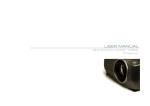
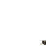
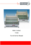
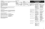
Series 6000 LHC
VME64x-Crate
User Manual
*00647.A1
*00647.A1
User’s Manual
W-Ie–Ne-R
VME 6021 CERN
Plein & Baus GmbH
General Remarks
The only purpose of this manual is a description of the product. It must not be interpreted as a declaration
of conformity for this product including the product and software.
W-Ie-Ne-R revises this product and manual without notice. Differences of the description in manual and
product are possible.
W-Ie-Ne-R excludes completely any liability for loss of profits, loss of business, loss of use or data,
interrupt of business, or for indirect, special incidental, or consequential damages of any kind, even if WIe-Ne-R has been advises of the possibility of such damages arising from any defect or error in this
manual or product.
Any use of the product which may influence health of human beings requires the express written
permission of W-Ie-Ne-R.
Products mentioned in this manual are mentioned for identification purposes only. Product names
appearing in this manual may or may not be registered trademarks or copyrights of their respective
companies.
No part of this product, including the product and the software may be reproduced, transmitted,
transcribed, stored in a retrieval system, or translated into any language in any form by any means with
the express written permission of W-Ie-Ne-R.
Detailed Information
This User Manual contains only rudimentary information to operate the device. To perform installation
and maintainance tasks it is necessary to read the “Series 6000 LHC VME64x-Crate Technical Manual”
(order no. *00571)
Control Cabinet
In the context of this user manual, the control cabinet must fulfill the requirements on fire-protective
enclosures according to EN 60950 / IEC 60950 / UL 60950.
The device is intended for operation in control cabinets or in closed areas. If operated outside of a control
cabinet, the front and back of the crate must be closed by the front pannels of the inserted VME-Modules/
Transition Modules or by a well fitted front plate. The LAN connection must be done via a shielded cable
with conductive connector shells, which are fixed with screws.
Furthermore, an additional fire-protective enclosure is required which must not affect proper air
circulation.
Mains Voltage and Connection
The Power supplies are equipped with a “World”- mains input (rated voltage range: 100-240 VAC,
frequency: 50-60 Hz, rated current: 16 A). Before connecting to the mains please double-check
correspondence.
Mains input connection at the power supply side is done with a 3-pin HIRSCHMANN connector or
power terminals. There is no main fuse inside. A circuit breaker for overcurrent protection 16A, type B or
C (EN / IEC 60898, VDE 0641), has to be installed externally.
Before disconnection the HIRSCHMANN connector, the power supply should be switched into standby
state. (Use the ON/OFF-Switch of the fan tray or the rocker switch beside the HIRSCHMANN connector
to switch into standby)
Hirschmann.
Pin 1
Pin 2
Pin 3
Earth
02.05.06
Signal
L
N
PE
Description
Phase
Return, Neutral
not connected
Protective Earth
2
Color of the Wire
black or brown
blue
green/yellow
*00647.A1
User’s Manual
VME 6021 CERN
W-Ie–Ne-R
Plein & Baus GmbH
Content
1
Operation, Function and Connections .............................................................................. 4
1.1 Power Supply Main Switch.......................................................................................... 4
1.2 Liquid cooled Power Supplies...................................................................................... 4
1.3 Fan Tray Operation and Control .................................................................................. 4
1.3.1 Hot Swapping of LX Fan Tray............................................................................. 4
1.3.2 LX fan-tray UEL 6020 Front panel with CANbus Connectors........................... 5
2
Technical Details.............................................................................................................. 6
2.1 EMI .............................................................................................................................. 6
2.2 Protection Provisions.................................................................................................... 7
2.3 Water cooled Versions, Flow Rates ............................................................................. 8
3
Conformity Certificate ..................................................................................................... 9
02.05.06
3
*00647.A1
User’s Manual
VME 6021 CERN
W-Ie–Ne-R
Plein & Baus GmbH
1
Operation, Function and Connections
1.1
Power Supply Main Switch
A rocker switch for AC on / off is situated at the rear side of the power supply.
Please note that this connector do not disconnect the power supply from mains completely!
Many internal components remains under high voltage (about 400VDC).
When this switch is in OFF Position ( O ) all other functions are disabled, including any remote control
action (remote monitoring is possible). Also the Main Switch at fan tray front panel doesn’t work until
the rear rocker switch is in “ON” ( | ) position again.
1.2
Liquid cooled Power Supplies
Liquid (water) cooled power supplies wit item numbers 0P07.xxxx and 0P17.xxxx should be always
operated with an adequate water flow (see 02.3). 0P07.xxxx is still equipped with aluminum heat
exchanger, 0P17.xxxx with stainless steel pipes.
Two water taps (input / output) with integrated valves are installed at the rear side of the power supply.
The tap-valves are closed when the mating parts have been removed. An overpressure valve prevents
damages of the cooling circuit by overpressure.
ATTENTION: Do not readjust the brass-screw of the valve.
1.3
Fan Tray Operation and Control
All monitoring and control operations are performed by a micro-processor based alarm and control circuit
placed inside the UEP 6021 power supply monitored by UEL 6020 fan trays. The reasons of a trip off will
be displayed on the alphanumerical display and monitored via network (CANbus).
Voltages, currents, cooling air temperatures, fan speed, power dissipation of inserted modules, operation
time of power supply and fan tray and net parameters can be shown on the fan-tray display.
1.3.1 Hot Swapping of LX Fan Tray
If the “hot swap” function is activated (AUTO OFF), the crate can be full powered during withdrawal of
the fan tray.
The power supply will trip off to prevent damage of inserted modules
1. if the operating time with removed fan tray is too long (30 seconds)
2. when the programmed second limit of slot 1 temperature sensor (or of optional installed ones)
exceed.
02.05.06
4
*00647.A1
User’s Manual
W-Ie–Ne-R
VME 6021 CERN
Plein & Baus GmbH
SYS Reset Switch (protected )
Power On LED
Main Switch ON / OFF;
Status LEDs:
Trip off Rest
Green
Yellow
Yellow
Red
Status
Fan Fail
Over Heat
SYS Fail
Alphanumeric Display
MODE SELECT Switch
Fan SPEED Switch and LED
AUTO OFF Switch and LED
Network ADDRess Switch
LOCAL Switch and LED
CANbus connector 1 female
CANbus connector 2 male
1.3.2 LX fan-tray UEL 6020
Front panel with CANbus Connectors
02.05.06
5
*00647.A1
User’s Manual
W-Ie–Ne-R
VME 6021 CERN
Plein & Baus GmbH
2
Technical Details
Rated Input Voltage:
Rated Input Current:
106 – 230 V AC, +/- 15% variation allowed
16 A
Sinusoidal:
Inrush current:
CE
EN 60555, IEC 555 pow. fact. 0,98 (230VAC),
16 A, cold unit
Output Insulation (SELF)
CE
EN 60950 , ISO 380, VDE 0805, UL 1950, C22.2.950
DC Output power with different input voltages at the rated current (16A), calculated with typical
efficiency of 75%
115VAC / 1.380Wnom, 1580Wpeak
230VAC / 2.760W, 3170Wpeak
(modules selected for 64x application, 5V- 3,3V-+/-12V- 48V)
Available modules
min. to max. range
Type MEH
Type MEH
Type MEH
2... 7,0V
7... 16V
30... 60V
115A / 630W
46A / 630W
13,5A / 650W
Type
Type
7...
7...
11,5A / 2x276W
23A / 2x276W
MDL (+/-)
MDH (+/-)
max. output, peak
24V
14V
nominal output
100A / 550W
40A / 550W
12A / 580W
10A / 2x240W
20A / 2x280W
Regulation
static: MEH 550W/650W
MDL/MDH
:
<15mV(+/-100% load, +/- full mains range)
<0,05%
(+/-100% load, +/- full mains range)
dyn.:
<100mV
<0,7%
(50% ⇔ 75% load, 1A/µs)
(+/-25% load, 1A/µs)
Recovery time +/-25% load:
Modules 550W
Modules 650W
MDL/MDH
within +-1%
< 0,2ms
< 0,5ms
0,0ms
within +-0,1%
< 0,5ms
< 1,0ms
< 1,0ms
Sense compensation range:
full difference between min. and max. output voltage
(OVP has to be adjusted accordingly)
MEH
MDL/MDH
Noise and Ripple
at Backplane side:
<20mVpp, (0-20MHz )
at Power Supply output:
<3mVrms (0-2MHz)
<40mVpp, (0-20MHz )
Efficiency:
<3mVrms (0-2MHz)
68% ... 85%, depends on used modules
MTBF
2.1
Power Supply air cooled
40°C ambient >65 000 h 25°C ambient >100 000h
Power supply water cooled
20-40°C water, 40°C ambient
>100.000h
EMI
RF-emission:
EMC immunity:
Operation temperature:
02.05.06
CE
CE
EN 61000-6-3:2001
EN 61000-6-2:2001
0....50°C without derating,
6
Storage:-30°C ... +85°C
*00647.A1
User’s Manual
VME 6021 CERN
W-Ie–Ne-R
Plein & Baus GmbH
2.2
Temp.-coefficient:
Stability (conditions const.):
< 0,2% / 10K
10mV or 0,1% / 24 hours, 25mV or 0,3% / 6 month
Current limits:
adjustable to any lower level
Voltage rise characteristics:
monotonic 50ms, processor controlled.
Protection Provisions
Overvoltage crow bar protection:
trip off adjusted to 125% of nominal voltage each output
DC Off (trip off)
within 5ms if >+5 /-2,5% (≥ 5V output) deviation from
nominal values, adjustable,
after overload, overheat, overvoltage, undervoltage (bad status) and
fan fail
Overtemperature:
DC Off (trip off)
Air cooled
if temperatures exceed 110°C heat sink, 70°C ambient
Water cooled
if heat exchanger temperature exceed 80°C
Trip off points adjustable, processor controlled. Output capacitors will be discharged by the crow bars
Overpressure Water cooled versions: 16-18 bar adjusted relief valve
02.05.06
7
*00647.A1
User’s Manual
W-Ie–Ne-R
VME 6021 CERN
Plein & Baus GmbH
2.3
Water cooled Versions, Flow Rates
Measured graphs of a typical power supply (5 modules):
Water temperature rise at different flow rates (power dissipation as parameter)
16,00
12,00
10,00
8,00
6,00
4,00
2,00
0,00
0,00
2,00
4,00
6,00
8,00
10,00
temperature rise [K]
Pv=100W
Pv=200W
Pv=300W
Pv=400W
Pv=500W
Pv=600W
Pv=700W
Pv=800W
Pv=900W
Pv=1000W
5 Liter/Minute
1Liter/Minute
F lo w - P re s s ure
12
10
flow rate [l/min]
flow rate [l/min]
14,00
8
6
4
2
0
0
2
4
6
8
10
12
d iffe re ntia l p re s s ure [1 0 ^5 P a ]
02.05.06
8
*00647.A1
14
User’s Manual
VME 6021 CERN
W-Ie–Ne-R
Plein & Baus GmbH
3
Conformity Certificate
02.05.06
9
*00647.A1
User’s Manual
W-Ie–Ne-R
VME 6021 CERN
Plein & Baus GmbH
EG-Konformitätserklärung nach Artikel 10.1 der Richtlinie 89/336/EWG (EMV-Richtlinie)
EC-Declaration of Conformity acc. to Article 10.1 of the Directive 89/336/EEC (EMC-Directive)
Déclaration de conformité CEE selon l’article 10.1 de la directive 89/336/CEE (Directive EMC)
Wir,
We,
Nous,
W-IE-NE-R Plein & Baus GmbH
Müllersbaum 20
51399 Burscheid-Hilgen
Name und Anschrift des Herstellers oder des in der EU niedergelassenen Inverkehrbringers
Name and address of the manufacturer or of the introducer of the product who is established in the EU
Nom et adresse du fabricant ou le la personne résidant dans la CEE qui introduit le sous-dit produit de la CEE
erklären in alleiniger Verantwortung, daß das Produkt
herewith take the sole responsibility to confirm that the product
soussignés déclarons de notre seule responsabilité que ce produit
Series 6000 LHC VME64x-Crate
Typenbezeichnung und ggf. Artikel-Nummer
Type designation and, if applicable, article no.
Type, nom et - si nécessaire - n° d’article du produit
mit den folgenden Normen bzw. normativen Dokumenten übereinstimmt
is in accordance with the following standards or standardized documents
est conforme aux normes ou spécifications Européennes suivantes
1.
2.
EN 61 000-6-3:2001
EN 55 022:1998
+ Corr:2001 + A1:2000 Kl. B
EN 55 022:1998
+ Corr:2001 + A1:2000 Kl. B
EN 61 000-3-2:2001
EN 61 000-3-3:1995 +Corr:1997 +A1:2001
EN 61 000-6-2:2001
EN 61 000-4-6:1996 + A1:2001
EN 61 000-4-3:1996 + A1:1998 + A2:2001
EN 61 000-4-4:1995 + A1:2001
EN 61 000-4-5:1995 + A1:2001
EN 61 000-4-11:1994 + A1:2000
EN 61 000-4-2:1995 + A1:1998 + A2:2001
Störaussendung EMA [RF emission]
Störspannung [conducted noise]
Störfeldstärke [radiated noise]
Oberschwingungen [harmonics]
Spannungsschwankungen [flicker]
Störfestigkeit EMB [immunity]
HF-Einströmung [injected HF currents]
HF-Felder [radiated HF fields] incl. ”900MHz”
Burst
Surge
Spannungs-Variationen [voltage variations]
ESD
Folgende Betriebsbedingungen und Einsatzumgebungen sind vorauszusetzen
The following operating conditions and installation arrangements have to be presumed
Les conditions d’opération et d’installation suivantes sont à respecter
______________________________________________________________________________
______________________________________________________________________________
Dieser Erklärung liegt zugrunde der Prüfbericht
This confirmation is based on testreport
Cette confirmation est basée sur report de test
21106924_001
TÜV Rheinland Product Safety GmbH, 51101 Köln, Allemagne
______________________________________________________________________________
Jürgen Baus, Techn. Director
Name, Anschrift, Datum und Unterschrift des rechtsverbindlich Verantwortlichen
Name, address, date and legally binding signature of the person being responsible
Nom, adresse, date et signature de la personne responsable
02.05.06
10
*00647.A1