1
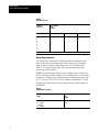
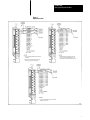
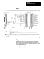
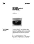
Product Data
Analog Input Expander Modules
AllenBradley
Analog Input Expander Modules
(Cat. No. 1771-E1, -E2, -E3)
Product Data
Introduction
Analog Input Expander Modules (cat. no. 1771-E1 -E2, -E3) are used with
an Analog Input Module (12-bit) Assembly (cat. no. 1771-IF, series B).
They provide a cost effective means of expanding the analog input
capacity of a PC system.
When using block transfer programming, you can use up to eight expander
modules with each analog input module. This allows as many as 64 analog
inputs (using 1771-E1 expanders) per analog input module. When using
single transfer programming, you can use up to eight expander modules
with each analog input module.
Each Bulletin 1771 I/O chassis can contain up to two expanded 1771-IF
analog input modules, provided that they are compatible with the other
modules in the chassis. For details regarding module compatability, refer to
the Analog Input Systems User’s Manual (publication 1771-803).
1
Product Data
Analog Input Expander Modules
The cat. no. 1771-E1 analog input expander module provides 8
single-ended inputs. It consists of the following hardware:
Analog Input Expander (12-bit) 8 Single-Ended Inputs (cat. no.
1771-E1C)
Field Wiring Arm (cat. no. 1771-WF)
Product Data (publication 1771-942)
The cat. no. 1771-E2 analog input expander module provides 6 differential
inputs. It consists of the following hardware:
Analog Input Expander (12-bit) 6 Differential Inputs (cat. no.
1771-E2C)
Field Wiring Arm (cat. no. 1771-WF)
Product Data (publication 1771-942)
The cat. no. 1771-E3 analog input expander module provides 6 two wire
sourcing inputs. It consists of the following hardware:
Analog Input Expander (12-bit) 6 Sourcing Inputs (cat. no. 1771-E3C)
Field Wiring Arm (cat. no. 1771-WF)
Product Data (publication 1771-942)
Operation
An analog input expander module acts as a data collector for an associated
1771-IF analog input module. It multiplexes its inputs into a single output
signal. This signal is then transmitted via cables to an analog input module.
The expander module communicates with the analog input module on the
I/O chassis backplane.
Installation
Installation of analog input expander modules includes selecting master
number, module number, number of channels, input and output ranges,
inserting the module in a 1771I/O chassis, connecting input and
interconnect cables, and keying the I/O chassis. The following paragraphs
describe the installation of analog input expander modules.
2
Product Data
Analog Input Expander Modules
Master Number Selection
Each input expander module sends its data to one analog input module.
The 1771-IF, series B analog input module is designated as either Master 1
or Master 2. If you plan to connect the input expander module to Master 1,
place a programming plug in the Master 1 position. If you plan to connect
the input expander module to Master 2, place a programming plug in the
Master 2 position.
Module Number Selection
Each Analog Input Expander Module (cat. no. 1771-E1, -E2, -E3)
associated with the same analog input module must be assigned a different
module number. To assign a module number to an input expander module,
place programming plugs in the positions specified in table A. Assign
module numbers consecutively, beginning with number 1, and don’t forget
to write the module number on the front panel of the module for future
reference. The module number must be between 1 and 8.
Table A
Module Number Selection
Expander
Number
1
2
3
4
5
6
7
8
Programming
Plug
Position
M2
M1
M0
0
0
0
0
1
1
1
1
0
0
1
1
0
0
1
1
0
1
0
1
0
1
0
1
Channel Selection
Before connecting your input expander modules, you need to select the
number of inputs which will be used. Select the number of channels by
placing programming plugs in the positions specified in table B.
3
Product Data
Analog Input Expander Modules
Table B
Channel Selection
Number of
Channels
1
2
3
4
5
6
71
81
Programming
Plug
Position
C2
C1
C0
0
0
0
0
1
1
1
1
0
0
1
1
0
0
1
1
0
1
0
1
0
1
0
1
1 Defaults to 6 for 1771E2 or 1771E3.
Output Range Selection
The output range of the analog expander module must match the input
range of the associated analog input module. You can select an output
range to match any input voltage range of the 1771-IF analog input
module. To select the output range, place programming plugs in the
positions specified in table C.
NOTE: The analog input module must be configured for a voltage range
for use with input expander modules. If it is configured for a current range,
change it to a voltage range as described in the Analog Input System (cat.
no. 1771-IF and 1771-El, E2, E3) User’s Manual (publication 1771-803).
Changing the output range does not require that the expander module be
recalibrated.
Table C
Output Range Selection
4
Output
Range
Programming
Plug
Position
+1 to +5V DC
0 to +5V DC
"10V DC
0 to +10V DC
G, H, I, K, L
G. H, I
F
G, I
Product Data
Analog Input Expander Modules
Input Range Selection
You can select one of the following input ranges for each 1771E1 or
1771-E2 input expander module:
-5 to +5V DC
0 to +5V DC
+1 to +5V DC
-10 to 10V DC
0 to +10V DC
+4 to +20mA
0 to +20mA
-20 to +20 mA
Table D shows the programming plug positions for each range. When
selecting a current range, be sure to use the S1 thru S8 positions for
1771-E1 expander modules and the D1 thru D6 positions for 1771-E2
expander modules.
Table D
Input Range Selections (1771El, E2)
Voltage
Range
Current
Range1
Programming Plug
Position
+1 to +5V DC
0 to +5V DC
10 to +10V DC
0 to +10V DC
5 to +5V DC
+4 to +20mA
0 to +20mA
A, C, D, E
A, C
No plugs
C
B
20 to +20MA
1 To select a current range for a given channel, place a programming plug in the corresponding
current range position The current range positions for 1771E1 expander modules are
labeled S1 thru S8 for channels 1 thru 8 respectively The current range positions for 1771 E2
expander modules are labeled D1 thru D6 for channels 1 thru 6 respectively
Two current ranges are available with 1771-E3 input expander modules: 0
to +20mA and +4 to +20 mA. The programming plug positions for these
ranges are shown in table E.
Changing the input ranges does not require that the expander module be
recalibrated (although the module calibration must still be checked
annually to maintain the specified accuracy).
5
Product Data
Analog Input Expander Modules
Table E
Input Current Range Selections (1771E3)
Input
Range
Programming
Plug
Position
+4 to +20mA
0 to +20mA
A, C, D, E
A, C
Input Connections
Connect inputs to the wiring arm of input expander modules as shown in
figure 1. Use consecutive channels beginning with channel 1. For example,
if you only use three channels on the expander module, they must be
channels 1, 2, and 3. Also, be sure that the input signals are compatible
with the input range selected for the expander module.
6
Product Data
Analog Input Expander Modules
Figure 1
Input Connections
7
Product Data
Analog Input Expander Modules
Output Connections
Connect the output of each expander module to the analog input module as
shown in figure 2. Be sure to connect each expander module to the
corresponding channel of the 1771-IF analog input module. For example,
expander module number 1 must be connected to channel 1 of the analog
input module.
External Power Supply Connections
External power supply connections are shown in figure 2. If the power
supply has a power available output, connect it to the power available
terminals of the analog input module. Otherwise, connect these terminals
together as shown in figure 2. Also, if you use the same power supply for
the expander module and the analog input module, the "15V DC common
terminal on the expander module is unused.
NOTE: All commons are connected internally.
8
Product Data
Analog Input Expander Modules
Figure 2
Output and Power Connections
Keying
After you decide which modules will be placed in each slot of the I/O
chassis, you should use keying bands to guard against having the wrong
type of module placed in a slot. The keying positions for each type of input
expander module is as follows:
cat. no. 1771-E1: 8-10 and 24-26
cat. no. 1771-E2: 2-4 and 12-14
cat. no. 1771-E3: 2-4 and 22-24
9
Product Data
Analog Input Expander Modules
Power Requirements
Analog Input Expander Modules (cat. no. 1771-E1, -E2, -E3) require
power from both the I/O chassis backplane and an external power supply.
You can use either the Power Supply (cat. no. 1770-P1) or the Remote
Power Supply (cat. no. 1778-P2) to provide external power to a 1771-E1 or
1771-E2 expander module. For a 1771-E3 expander module, use a Remote
Power Supply (cat. no. 1778-P2).
Each expander module requires 150mA from the I/O chassis backplane. Be
sure to consider this and the backplane current requirements of other
modules in the chassis to ensure that the backplane capacity is not
exceeded.
Specifications
Inputs per Module
Cat. No. 1771E1
G 8 singleended
Cat. No. 1771E2
G 6 differential
Cat. No. 1771E3
G 6 twowire sourcing
Module Location
G 1771 I/O rack
Input Ranges
Cat. No. 1771E1 and Cat. No.
1771E2
G +1 to +5V DC
G 10 to +10V DC
G 0 to +5V DC
G 0 to +10V DC
G 5 to +5V DC,
G +4 to +20mA
G 0 to +20mA
G 20 to +20mA
Cat. No. 1771E3
G 4 to +20mA and 0 to +20mA
Accuracy
G "0.05 percent of range (voltage
mode)
G "0.07 percent of range (current
mode)
10
Product Data
Analog Input Expander Modules
Temperature Coefficient
Cat. No. 1771E1
G "35 ppm/°C (voltage mode)
G "45 ppm/°C (current mode)
Cat. No. 1771E2
G "40 ppm/_C (voltage mode)
G "50 ppm/_C (current mode)
Cat. No. 1771E3
G "45 ppm/_C
Input Overvoltage Protection
G "25V rms (voltage mode)
G "30mA (current mode)
Common Mode Voltage Cat. No.
1771E2
G "10V
Common Mode Refection Ratio
Cat. No. 1771E2
G 80 dB, DC to 120Hz (voltage
mode)
G 20V pp, DC to 120Hz (current
mode)
Input Impedance Cat. No. 1771E1
and Cat. No. 1771E2
G 109 ohms (voltage mode)
G 250 ohms (current mode)
Internal Loop Impedance
Cat. No. 1771E3
G 285 ohms
Maximum External Loop
Impedance Cat. No. 1771E31
G 1000 ohms for 20mA
Backplane Power Supply
Current Requirement
G 5V DC +150mA
External Power Supply Current
Requirement Cat. No. 1771E1
And Cat. No. 1771E2
G +15V DC 50mA
G 15V DC 50mA
Cat. No. 1771E32
G +15V DC 200mA
G 15V DC 200mA
Ambient Temperature Ratings
Operational
G 0_C to 60_C (32_F to 140_F )
Storage
G 40_C to 85_C (40_F to 185_F)
11
Product Data
Analog Input Expander Modules
Relative Humidity Rating
G 5 to 95% (without condensation)
Electrical Isolation
G 1500V rms, (transient)
Keying
Cat. No. 1771E1
G 810 and 2426
Cat. No. 1771E2
G 24 and 1214
Cat. No. 1771E3
G 24 and 2224
Output to 1771IF Series B
G +1 to +5V DC
G 10 to +10V DC
G 0 to +10V DC 0 to +5V DC
1The 1000 ohms is the maximum external loop impedance at which the cat. no. 1771E3 expander module can source +20mA/
This impedance is also dependant upon the isolated transmitter's specifications. Refer to transmitter data sheets for further
information.
2The cat. no. 1771E3 expander nodule provides six 26V DC 2wire sourcing inputs for use with 2wire transmitters. The 26V DC
is derived from the 30V difference between the +15V and 15V external power supply.
With offices in major cities worldwide
WORLD
HEADQUARTERS
Allen-Bradley
1201 South Second Street
Milwaukee, WI 53204 USA
Tel: (1) 414 382-2000
Telex: 43 11 016
FAX: (1) 414 382-4444
EUROPE/MIDDLE
EAST/AFRICA
HEADQUARTERS
Allen-Bradley Europe B.V.
Amsterdamseweg 15
1422 AC Uithoorn
The Netherlands
Tel: (31) 2975/43500
Telex: (844) 18042
FAX: (31) 2975/60222
As a subsidiary of Rockwell International, one of the world’s largest technology
companies — Allen-Bradley meets today’s challenges of industrial automation with over
85 years of practical plant-floor experience. More than 11,000 employees throughout the
world design, manufacture and apply a wide range of control and automation products
and supporting services to help our customers continuously improve quality, productivity
and time to market. These products and services not only control individual machines but
integrate the manufacturing process, while providing access to vital plant floor data that
can be used to support decision-making throughout the enterprise.
ASIA/PACIFIC
HEADQUARTERS
Allen-Bradley (Hong Kong)
Limited
Room 1006, Block B, Sea
View Estate
28 Watson Road
Hong Kong
Tel: (852) 887-4788
Telex: (780) 64347
FAX: (852) 510-9436
CANADA
HEADQUARTERS
Allen-Bradley Canada
Limited
135 Dundas Street
Cambridge, Ontario N1R
5X1
Canada
Tel: (1) 519 623-1810
FAX: (1) 519 623-8930
LATIN AMERICA
HEADQUARTERS
Allen-Bradley
1201 South Second Street
Milwaukee, WI 53204 USA
Tel: (1) 414 382-2000
Telex: 43 11 016
FAX: (1) 414 382-2400
Publication 1771-2.30 — September, 1983
Supersedes Publication 1771-942 — June, 1983
12
Printed in USA