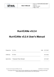
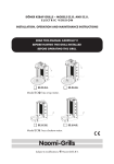
1
Installation & user manual sampling systems Version 030414UK Efcon® Installation & User manual. Sampling systems Page 1 Installation & user manual sampling systems Version 030414UK Table of content 1.1 General 1.2 Application area 1.3 Transportation 1.4 System set-up Page 4 4,5 5 5, 6 2 2.1 2.2 2.3 2.3.1 2.3.2 2.5 2.6 6…12 6, 7 7, 8 8…10 8 9, 10 12 12 Enclosure Technical specifications Dimensions and parts Installation Mechanical installation Electric installation Maintenance Trouble shooting 3 Controller Setting 3.1 Technical specifications 3.2 Operation explanation 3.2.1 Sampling 3.2.2 Container distributor system 3.2.3 Counter function 3.2.4 Alarm function 3.2.5 Sampling on programmed periods 3.2.6 Stop sampling after xx container changes 3.3 Manual operation 3.4 Counter read out 3.5 Change sampler settings 3.5.1 Read out 3.5.2 Date / time 3.5.3 Sampling settings 3.5.4.1 Time-/volume proportional sampling 3.5.4.2 Batch TPS (time proportional sampling) 3.5.5 Sampling interval 3.5.6 Distributor settings 3.5.7 Distributor time interval 3.5.8 Turning distributor after xx samples 3.5.9 Stop sampling when container is filled 3.5.10 Cool unit settings 3.5.11 Sampling on programmed period/day interval 3.5.12 Stop sampling after xx container changements 3.6 Change software 11…19 11 11, 12 12 12, 13 13 13 13 13 13, 14 14 14…19 14 14 15, 16 17 17 17 18 18 18 18 18, 19 19, 20 20 20 4 4.1 4.2 4.3 4.4 4.5 4.6 4.7 21…24 21 21 22 22, 23 23 23, 24 25 Vacuum sampler Technical specifications Measurements and parts Principle of operation Installation instructions Changing sample volume Maintenance Trouble shooting Page 2 Installation & user manual sampling systems Version 030414UK Table of Content 5 ILS Guillotine G05 sampler 5.1 Technical specifications 5.2 Measurements and parts 5.3 Principle of operation 5.4 Installation instructions 5.5 Changing sample volume 5.6 Maintenance 5.7 Trouble shooting 25…28 25 25 26 27 27 27 28 6 6.1 6.2 6.3 6.4 6.5 6.6 ILS 2-way sampler Technical specifications Measurements and parts Principle of operation Changing sample volume Maintenance Trouble shooting 28…32 28 29 29 30 31 32 7 7.1 7.2 7.3 7.4 7.5 7.6 7.7 ILS 3-way SS sampler Technical specifications Measurements and parts Principle of operation Installation instructions Changing sample volume Maintenance Trouble shooting 32…36 32 33 33 34 34 35 36 8 8.1 8.2 8.3 8.4 8.5 8.6 8.7 ILS 3-way PVC sampler Technical specifications Measurements and parts Principle of operation Installation instructions Changing sample volume Maintenance Trouble shooting 36…39 36 37 37 37, 38 39 39 39 9 9.1 9.2 9.3 9.4 9.5 9.6 9.7 Peristaltic Sampler Technical specifications Measurements and parts Principle of operation Installation instructions Changing Maintenance Trouble shooting 40 40 40 41 41 42 42 43 9 Spare parts 44 10 CE Declaration 45 Page 3 Installation & user manual sampling systems Version 030414UK 1.1 General Efcon® is developed by A.V.M. / Netherlands as a complete Effluent Control Systems. Efcon® products are designed for measuring and controlling waste water flows. Efcon® products fulfil to the tough Dutch regulations NEN 6600-1 and the international standards ISO 5667-2/3&10. Products from the Efcon® program are: Samplers (several types), level controllers, pump controllers, registration equipment, sample distributor systems, flowmeters industrial and sewers, measurement pit, cool units, mobile systems, etc. BEFORE YOU START: Read the manual before you connect the unit to a power supply or install. In case of illegal use or use in non-defined area’s any form of warranty will be denied. The user needs to be informed about the users manual and application dangers. Installing and adjusting parameters of the sampling system should be done by qualified personnel . Check if the equipment is transported without transport damage. In case of damage directly contact your supplier and do not install the equipment. The equipment is tested in the AVM factory in Hei- en Boeicop, Netherlands to different quality tests before it is transported. Required maintenance or repair, which will not influence the warranty period, will have to be done by trained Efcon® specialists. All equipment returned to AVM needs to be cleaned, sterilised and transported in a safe enclosure to avoid health-threatening situations. In case of service or repair, the equipment will not be accepted by AVM if there is no declaration of origin and safety added to the equipment. Extra cleaning can be refused or will be charged! Warranty will be denied if there are mechanical, electronic or software changes in the unit which are not performed by AVM. BASIC WARRANTY PERIODS: 12 months after delivery for Efcon equipment ex. Works used and installed according specifications, 150 samples and 24 distributor turns a day in a non aggressive well ventilated environment. 48 months for thermoplastic enclosures on stationair use according installation 1.2 Application area Efcon® equipment Be aware! wrong application or misuse can damage the equipment or the surrounding of the unit and is not covered by any form of warranty. Page 4 Installation & user manual sampling systems Version 030414UK Surrounding conditions: • Temperature: 0°C / +40°C. (-25°C / + 55°C optional) • Well ventilated space • AVM advises not to place the enclosure into direct sun light, for an optimal cooler output. Systems in direct sun light cool less efficient due to a higher surrounding temperature! Use in explosion hazardous environment is prohibited unless mentioned on product and manual! Sample Medium: • Free of solid parts (Guillotine excluded.) • Free of air inclusion • Temperature: +0,1°C / +50°C. (higher optional) • Minimal conductivity: 50µS (only for vacuum systems) 1.3 • • Transportation Transport all systems equipped with a cool unit straight up. For warranty claims send the system packed in the original package and on the supplied pallet. 1.4 System set up Efcon® sampling systems are available in different thermoplastic enclosures and are standard equipped with a SIEMENS logo controller. Efcon® sampling systems can be supplied in various operation principles, for different circumstances, according NEN 6600-1 & ISO 5667-2&10. Standard enclosures: • Efcon®omy Monoblock: On request in mobile available (with wheels and carry brackets), • Efcon® Industrial: Industrial model with Plug-In-Cool unit. Bigger compartment for electronic components like recorders / measurement electronics / etc. • Efcon® CarryBox: Portable enclosure for vacuum samplers without cooler, • Efcon®omy SystemBox: Enclosure to build in flowmeters, samplers, air compressors etc. Combinable with Efcon®omy Monoblock enclosure. • Efcon® industrial SystemBox: Enclosure to build in flowmeters, samplers, air compressors, CIP installations, switch boxes etc. Combinable with Efcon® industrial enclosure. CPU’s: • Siemens LOGO: With basic functionality. • On request custom made controllers. Page 5 Installation & user manual sampling systems Version 030414UK Sampling principles: • Vacuum principle: Suction system from open channels • In-line principle: In-Line-Sampler (ILS) are suited for waste water sampling from 100% filled pipes and available in different types: • ILS Guillotine: pneumatic driven SS 316 sampler, for raw waste water. • ILS 3WP *22: pneumatic driven, SS 316 flush system for raw waste water, available in multiple diameters and pressure classes. • ILS 3WE *12: electric driven, cost-effective PVC flush system, with SS 316 sample bullet, available in multiple diameters and pressure classes. • ILS 2WE 412: electric , cost-effective PVC-sampler met RVS 316 sample bullet. 2 2.1 Efcon® omy enclosure Technical specifications Efcon®omy Electric: • Power supply / current • Power Enclosure: • Height • Width • Depth • Material enclosure • Material window • Material plates • Isolation Surrounding conditions • Protection class • Ambient temperature • Direct sunrays • Zone Cooling characteristics : • Principle • Coolant • Evaporator spiral • Compressor • Condenser • Cool temperature • Defrost cycle • Heater Sample container • without distributor • with direct distributor • CE-Declaration Page 6 230V AC ±5% / 2,5 A / 50 Hz ± 400 W Thermoplastic Green (different colours optional) • 1100 mm ± 2% • 600 mm ± 2% • 600 mm ± 2% • LLDPE double wall according AVM patent • Polycarbonate • SS 316 / PE • 40 tot 60 mm PUR foam • IP 54/ Cool shaft IP23 • ( option -25°C) 0 / +40°C (optional +55°C) • Allowed, if possible avoid • Not in explosion hazardous environments. • Forced 24VDC ventilator moist protected • R134A • Efcon® RVS 316 / V4A • Electrolux coated • Coated • +3°C tot +5°C according NEN6600-ISO 5667 • Automatic (adjustable on controller) • 24VDC-25W SS spiral (Option) Material Polyethylene – White (optional glass) • from 2L till 50L • 2x25L / 4x13,5L / 12x2L / 24x1L • Yes Installation & user manual sampling systems Version 030414UK Efcon® Carrybox (vacuum sampler) Electric : • Power supply / current • Power Enclosure • Height • Width • Depth • Weight • Material • Back plate Surrounding conditions • Protection class • Ambient temperature •Direct sunray • Zone 2.2 230V AC ±5% / 1 A / 50 Hz ± 100 W Thermoplastic Green portable model • 412 mm± 2% • 340 mm ± 2% • 302 mm ±2% • ± 9 kg • LLDPE • Aluminium with suspension bracket • IP 41 • 0°C / +40°C • Possible, if possible avoid • Not in explosion hazardous environments. Measurements and parts Efcon®omy enclosure A F C B B G J H I E E D Fig. 2.2a A) B) C) D) E) F) G) H) I) J) Main switch (left side standard) Sample/suction hose inlet Protect cover of the cool shaft Power supply Mounting brackets Elektra front plate with buttons and display Sample Garniture (only for vacuum systems) Distributor engine with bracket Sample container Cooled sample storage compartment Page 7 Installation & user manual sampling systems Version 030414UK Carry-Box Enclosure A Ef con R H E B C F F D D Fig. 2.2b A) B) C) D) E) F) G) H) Handle Operating panel Vacuum chamber Pincher Splash board Connectors Power supply Suspension bracket 2.3 Installation 2.3.1 Mechanical: Before installing the enclosure, determine first where the sampler is placed (in case of an ILS systems). This way you can check if the sample hose (from sampler to enclosure) has an gradual slope. Efcon®omy enclosure Place the enclosure on a firm horizontal (water-levelled) ground and fix the enclosure with the two supplied SS mounting brackets, bolts en plugs. BE CAREFULL! When fastening the M6 bolt, don’t fasten to hard in the enclosure. A Beneath the enclosure a condensate drain outlet is fitted. The outlet has a push-in fitting for 8mm tubing. See fig. 2.3a Fig. 2.3a Carry enclosure This enclosure is only available for vacuum samplers. Mount ±300 mm DIN-rail horizontal to the wall on which the enclosure is placed. Make sure there is sufficient height for an gradual, siphons free and nod free sample drain to the container. Page 8 Installation & user manual sampling systems Version 030414UK A B Fig. 2.3b 2.3.2 Electric: Work as followed when installing the enclosure: • Remove the protection cover (B in fig.2.3b) from the cool shaft by loosening the four bolts which hold the cover. If necessary remove the connector and earth cable from the fan on the cover to create more working space. Loosen the two grip nuts from the electro front plate (A in fig.2.3b). Unplug the connectors from the front plate to remove the plate from the enclosure • Pull the connection cable through the cable tubes which run through the enclosure(A in Fig.2.3c). • Pull the cable through the cable glands (B in fig.2.3c) on the separation plate between the cool shaft and electronic compartment. Strip the cables long enough to reach the terminal. B A Terminal connections Fig. 2.3c Read Manual before installation • • • Fig. 2.3d • • Power supply Connect the power supply cable(230VAC/50Hz) to contacts 1 (ground), 2 (live) and 3 (null) of the terminal (see sticker in fig.2.3d). Pulse Input Connect the potential free pulse/batch contact to contacts 4 and 5. (pulse input) for pulse registration and pulse proportional sampling. When using the pulse input for batch control sampling, the pulse counter in the display counts every batch contact. Be ware: keep the pulse input frequency <1 Hz. Use a pulse length of ±100 msec. Distributor input (optional) Connect a potential free contact to contact 6 and 7. By making contact on this input it’s possible to activate the distributor externally. Start /stop auto sampling input (optional) Connect 8 & 9 to a potential contact to remotely start the automatic sampling program. The sampler will start the automatic sampling when the contact closes. Alarm contact Connect the cable for the alarm relay contact to contacts 10 and 11 (alarm output). Page 9 Installation & user manual sampling systems Version 030414UK In-/output Connectors (Optional) Optional for Efcon® systems are connectors on the side available. Connect the pins of the connectors according fig 2.3d. Places the connectors with its cable inlet downward to prevent moisture inside the connector. Fig.2.3e 230VAC Power supply in (male connector) • Pin 1 = L 230VAC 50Hz Pin 2 = N 230VAC 50Hz Pin PE= GND 24VDC Power supply in (female connector) • Pin 1 = +24V DC Pin 2 = -24V DC (gnd) Pulse Input (female connector) • Pen 3 & PE= potential free contact Distributor Input (female connector) • Pen 3 & 2= potential free contact Sampler Output (female connector) • Pen 1= +24VDC sampler • Pen 2= -24VDC sampler • Pen 3= sampler response signal (24VDC pulse) optional Alarm Output (male connector) • Pen 1 & 2= Alarm output (potential free contact) 230VAC Power supply out (female connector) • Pin 1 = L 230VAC 50Hz Pin 2 = N 230VAC 50Hz Pin PE= GND Page 10 Installation & user manual sampling systems Version 030414UK 2.4 Maintenance BE AWARE! Before maintenance or revision switch off power supply, remove compressed air couplings and remove pressure and medium from waste water piping. Maintenance and reparations should be done by qualified personnel. Avoid direct contact with waste water, use/maintenance/reparation protective gloves. wear during The maintenance frequency depends on and waste water characteristics. Clean (or replace if necessary) all parts which come in contact with the sampled medium regular Check if the cool shaft of cooler is clean and is not clogged by dust . Cleaning the enclosure can be done with a moist cloth, but avoid all electrical parts. Check yearly if the screws of all the electronic connection are tightened. 2.5 Trouble shooting Problem Diagnose Cooler freezes the containers Wrong settings controller Door not closed Door “leaks” air. 24VDC circuit out of range Cooler doesn’t cool Distributor does not turn (properly) Page 11 Wrong settings controller Fan inside the protection cover doesn’t work Wrong distributor settings Hex.bolt on the distributor engine is loose. Silicon hose doesn’t turn free in rotation Solution Check setting (§1.7) Close door, check rubber seal of the door with a flash light. Adjust the potmeter on the power supply to 24,00VDC ±0,10 VDC. Check settings (§1.7) Check/replace fan Check settings (§1.7) Fasten bolt Shorten silicone hose Installation & user manual sampling systems Version 030414UK 3 Program settings BE WARE! Faulty settings may lead to defect hardware. Adjusting parameter settings should be done by qualified personel. 3.1 Technical specifications Siemens LOGO with display and operating buttons • I/O • Internal real time Clock • Summer /winter time • Time / volume proportional • Distributor turntime adjust. • Container overflow protection • Output Alarm error samples • Counters • Sampling on programmed periods Operating: • Pulse input • Manual operation • Changing setting • 8/12 of 4/8 output depends on type • Yes, year, date, time • Yes, Automatic • Sampling on time or volume (pulse) interval, or batch controlled time proportional sampling. • on time (3x), days of the week • Yes, adjustable • Yes, Pot. free relay contact - default 3 (adjust) • Pulse total & Sample total • Yes, 2 programmable periods • 100 msec Pot. free contact, frequency <1Hz. • 4 push button: manual sample, next container, alarm reset, reset counters • On DISPLAY CPU in front of Efcon®omy Possible on display SIEMENS 3.2 Operation explanation 3.2.1 Sampling Sampling system can take samples on three different principles: • Manual sample, by pushing a button on the operation panel. • Automatic sample, as programmed Time proportional sampling, Volume proportional (via pulse input) sampling or Batch Time proportional sampling (start time proportional sampling when the puls input is active). • Automatic sample on programmed start- and stop date 3.2.2 Container distributor system (optional) The distributor ensures a proper sample distribution across different sample containers. Systems with multiple sample container are equipped with a direct distributor. The distributor positions the sample hose from the sampler (clockwise) above the container. This operates automatically (by program) of manually (by push button). The distributor is programmable to turn on: • • Fixed time (example: set on 10:00) & days (3 times a day). Time interval (example every 2 hours), time interval starts after programmed fixed time. • After a number of taken samples, dependable on sample and container volume (overflow protection)* Page 12 Installation & user manual sampling systems Version 030414UK * When the distributor turns manually the counted samples reset to zero. 3.2.3 Counter function (optional) The Siemens LOGO-display show counted pulses and taken samples and stores up to 3 distributor rotations. These counters can be reset by the push button “reset counters” on front of the system. Optional are mechanical counter (fixed and with reset) available which are placed in front. 3.2.4 Alarm function (optional for In Line Samplers) After multiple sample failures or power failure the alarm output relay of the sampling system closes. When a sample cycle is not completed the CPU registers an error sample. After a set number of error samples (default =3) the system stops taking automatic samples and switches to alarm condition. The alarm is perceptible on 2 ways: • • Alarm output relays switches Display describes current alarm status Push the alarm-reset button in front of de enclosure to reset the alarm. After resetting the system will sample according program. Also when power failure accurse the alarm contact closes. 3.2.5 Sampling on programmed periods By activating this setting it is possible to start and stop automatic sampling on a programmed date and time. This way the system can be programmed(§3.5.11) to only take samples. • • Weekly, example: only automatic volume proportional sampling every Friday from 08:00 till Saturday 08:00. Period, example: Monday 09:00 11th march 2006 start with automatic sampling. Monday 09:00 18 march 2006 stop automatic sampling. 3.2.6 Stop sampling after xx containers When activated the sampler stops sampling after a programmed number of containers. By pushing reset the system samples further until the same number of samples is taken. §3.5.12 3.3 Manual operation The sampling system can be manually operated by four push button in front of the enclosure. • • Manual Sample, push to take an manual sample. Next Bottle, push to turn the distributor to the next container. Page 13 Installation & user manual sampling systems Version 030414UK • The distributor will wait 20 seconds when a sample is taken, to finish the sample cycle. Reset Counters, push to reset counters. Reset alarm, if the alarm is activated (to many error samples), push this button to reset the alarm. The automatic sampling is controlled by a Siemens LOGO, placed in the front behind a splash cover. Push de 2 closing lips with thumb en point finger to open the cover and access the Siemens LOGO to change settings. 3.4 Read out When the sampling system is not equipped with a distribution system the display shows a pulse and sample counter. Sampling systems equipped with a container distribution system store, when the distributor turns, counted pulses and samples. The display of the Siemens LOGO registers counters of the last 3 distributor turns. 3.5 Changing Sampler settings(siemens CPU) To change settings it is necessary to enter the program of the SIEMENS LOGO! Be aware! : When entering the program menu, don’t erase the program from the cartridge. 3.5.1 Changing displays By pushing the cursor buttons next to the display it’s possible to toggel between counter read outs. By pushing or the display switches from pulse counters to sample counters. Only from the date/time display with the escape button it is ossible to enter the parameters MO 10:46 02.20.02 SET CLOCK MO 10:56 MM-DD-YY 02-14-02 >Stop Set Param Set.. Prg Name SET CLOCK SU 00:00 MM-DD-YY 01-01-00 Stop Set Param >Set.. SET CLOCK MO 10:56 MM-DD-YY 02-14-02 >Clock Contrast Startscree Fig. 3.5a >Set Clock S/W Time.. Sync 3.5.2 • • • • • • • Changing date/time Select date/time display & press ESC. Select Settings with . Select clock with . Press OK to select Change date/time with the cursor buttons. Select the digit to change with and , change the digit with or . Press OK to store changed values. Press ESC to return to the date/time display. After power failure short then 48 hours the SIEMENS logo will keep its date/time, after a longer period it is possible these settings need to be adjusted. Thee clock function switches automatically between summer and winter time. Page 14 Installation & user manual sampling systems Version 030414UK 3.5.3 • • • • MO 10:46 02.20.02 >Stop Set Param Set.. Prg Name • Stop >Set Param Set.. Prg Name Timer Timer Switch=Off Switch=On Pulsintv On = 10 Off= 10 Cnt=000000 Pulsintv On =000010 Off=000010 Cnt=000000 Pulsintv On =000020 Off=000020 Cnt=000000 Timeintv T =10:00m Timeintv T =15:00m Timeintv T =10:00m Ta=00:00m Ta=00:00m Ta=00:00m TurnTime D=MTWTFSS On =09:00 Off=09:01 TurnTime D=MTWTFSS On =09:00 Off=09:01 TurnTime D=MTWTF-On =08:00 Off=08:01 Timer Switch=Off ETC, check table 3.5a Fig. 3.5b • • Changing sampling settings Select date/time display and press ESC . Select Set Param with . Press OK to select. Select the Parameter to change with or and press OK to select. Select the digit to change with en , change the digit with or . See table 3.5 for a parameter summary. Press OK to store changed values. Press ESC to return to date/time display. Software for SL1xxxxx & SL2/3/4/5/6xxxxxx Parameter Description Default Timer Choose time of pulse proportional automatic sampling Timer Off= Pulse proportional program Switch off On = Time proportional program PulsIntv Choose sample interval when sampling pulse proportional pulsintv automatic sampling On = 10 (1&2) On = fill in desire pulse interval Off= 10 Off= confirm with same value Cnt= 0 Cnt= actual number of pulses since last taken sample. STV= Start Value (keep on 000000), (don’t change!) STV=0 TimeIntv Choose sample interval when sampling time proportional timeintv T = fill in desired time interval T = 15:00m Ta= actual time since last taken sample Ta= 00:00m BatchTPS Use pulse input for time proportional sampling when the input is BatchTPS closed. Off = normal pulse proportional sampling Switch =Off On = Time proportional sampling when pulse input is closed TurnTime Distributor turn time (3x) turntime 1,2,3 MTWTFSS = Remove days when the distributor doesn’t move MTWTFZZ ON = fill in desired turn time ON= 08:00 OFF = fill in ON-time + 1 minute OFF=08:00 TurnTime 4 Don’t change this setting TurnTime 4 TurnIntv TurnIntv OverFlow 1&2 ContFull TurnStep 1&2 Errormax 1&2 Pulse = Off Distributor time interval on-off On = Time interval on Off= Time interval off Adjustable time interval distributor, use parameter TurnTime to time the start of the interval T = fill in desired time interval Ta= Actual interval timer Turn distributor after xx taken samples. Calculate container volume / sample volume and fill in value minus ± 5% for overflow protection. On = Fill in maximum number of sample Off = Confirm with same value Cnt = Actual number of samples in current container STV= Start Value (keep on 000000), (don’t change!) Set to stop sampling when the container is has reached the number of samples entered in the Overflow parameter. Only for 1 container systems. Off= Continuously sampling On = Stop sampling when parameter Overflow is reached. Number of distributor steps till next container. Fill in 24 / number of containers. On = fill in desired value (6 for a 4 container system) Off= confirm with same value Cnt= Actual number of of steps STV= Start Value (keep on 000000), (don’t change!) Maximum number of error samples On = Fill in maximum number of allowed consecutive error samples (don’t fill in 0) Off = Confirm with same value Cnt = Actual number of error samples STV= Start Value (keep on 000000), (don’t change!) Page 15 Pulse = Off TurnIntv Switch = off TurnIntv T = 24 Ta= 24 Overflow On = 240 Off= 240 Cnt= 0 STV= 0 ContFull Switch=Of TurnStep On = 6 Off= 6 Cnt= 0 STV= 0 Errormax On = 3 Off= 3 Cnt= 0 STV= 0 Installation & user manual sampling systems Version 030414UK Purge Purge time T = fill in desired Purge time Ta= actual value of Purge timer Maximum suction time. T = fill in maximum Ta= actual suction time Dose time T = fill in desired dose time Ta= actual dose timer Select if the sampler needs to create pressure during the release of the sample. On= Create pressure during sample release Off= Don’t create pressure during sample release Rinse time: Time to clear the water from the tubing and suctionhose after dosing. For peristaltic pumps only. T = fill in the needed rinse time Ta= actual rinse timer Activation time sampler. For pneumatic samplers default 3 sec. For electric samplers default 16 sec. T = Fill in the needed activation time (+flush time). Ta= Actual timer Sampler equipped with response contact On = Response contact on Off= Response contact off Cool Unit set points On = Set point high (5 °C) Off = Set point low (2° C) Ax = Current temperature inside sample storage compartment Heater set points On = Set point high (1 °C) Off = Set point low (0° C) Ax = Current temperature inside sample storage compartment Delay time Cool unit, T = Delay time for Ta= Time passed Defrost cycle, with this interval the cool unit stops automatically to defrost. TH = Defrost interval TL = Defrost time (time the cool unit switches off) Ta = Actual time interval timer Start cool unit on the first taken sample, reset by reset buttons. On = Cool when sampling Off= Continuous cooling Manual defrost function, On = Stop cool unit to defrost Off= Continue cooling ECO cool function, when equipped with a door switch the sampler turn the cool unit off after the door is opened. On= cool unit doesn’t stop after door opening Off= cool unit turn off after door opening ECO cool delay, delay time tostop the cool unit after the door has been openend. T = delay time Ta= Actual time Start and Stop program On = Start and stop program active Off= Continuous sampling Time start automatic sampling MTWTFSS = don’t change On = Start time Off= Start time +1 minute Start-T 2 and 3 don’t use Purge T =10:00s Ta= 00:00s Suction T =30:00s Ta=00:00s Dose T =10:00s Ta= 00:00s OpenBlow Don’t change this setting , it should be set to: Pulse = Off Start date automatic sampling, when ST/STP is ON. Yearly= don’t change! Keep on Monthly= don’t change! Keep off Pulse= don’t change! Keep off Start-T 4 Pulse = Off Start –D1 1 Yearly= On Monthly= Off Pulse= Off ProgramD 2 On = Fill in desired start date ProgramD 3 Off= Fill in desired start date + one day (keep the on 2099) Start-D1 2 ON: YYYY-MM-DD 2000-01-01 Start-D1 3 Suction Dose OpenBlow RinseT ContactT Response (optional) CoolUnit Heater Delay C Defr.Cyc CoolSamp Defrost ECO Cool ECODelay Program Program1 Program 4 ProgramD 1 Page 16 Switch=On RinseT T =10:00s Ta=00:00s ContactT T = 03:00s Ta= 00:00s Response Switch=off CoolUnit On = 5 Off= 2 Ax= 0 Heater On = 1 Off= 0 Ax= 0 Delay C T = 60:00 s Defr.Cyc TH = 03:00h TL = 15:00m Ta = 00:00 CoolSamp Switch=Off Defrost Switch=Off ECO Cool Switch=- Off ECODelay T = 09:00h Ta= 00:00h ST/STP Switch=Off Start-T 1 MTWTFSS On = 08:00 Off= 08:01 Installation & user manual sampling systems Version 030414UK StopCont 1 StopCont 2 Stop continuous sampling after xx containers On = Fill in when the sampler needs to stop auto sampling Off= Confirm with same value Cnt= Actual number of sampled bottles STV= Start Value (keep on 000000), don’t change VS / ILS Sample principle, select how the sampler should take a sample. Beware don’t change Switch= OFF for vacuum samplers (don’t change) Switch= ON for ILS samplers (Don’t change) Table 3.5 “Software settings Vacuum systems” Parameters with a orange background only for vacuum systems Parameters with a green background only for ILS systems • OFF: YYYY-MM-DD 2099-01-01 StopCont On = 24 Off= 24 Cnt= 0 StopCont 2 STV= 0 VS / ILS Switch= Off Special software of on request available. 3.5.4.1 Time/volume proportional sampling • Select Set Param • Press to select parameter Timer and press OK. • Press or to switch from ON (Time proportional) or OFF (volume proportional). • Press OK to store changes. 3.5.4.2 Batch TPS (time proportional sampling) • Select Set Param • Press to select parameter BatchTPS and press OK. • Press or to switch from ON (Time proportional) or OFF (volume proportional). • Press OK to store changes. 3.5.5 Changing sample interval For volume proportional: • Select Set Param. • Press to select PulsIntv and press OK. • Fill in next to On the desired pulse interval and confirm this value next to Off. Select the digit to change by pressing or , change the digit with or . • Press OK to store changes. For time proportional sampling • Select Set Param. • Press to select TimeIntv and press OK. • Fill in next to On the desired pulse interval and confirm this value next to Off. Select the digit to change by pressing or , change the digit with or . • Press OK to store changes. Page 17 Installation & user manual sampling systems Version 030414UK 3.5.6 • • • • Settings: TurnTime_1 SMTWTFS On =08:00 Off=08:01 TurnIntv Switch=Off Distributor turn 00:00 08:00 16:00 00:00 08:00 00:00 08:00 Fig. 3.5.c Settings: TurnTime_1 SMTWTFS On =08:00 Off=08:01 TurnIntv TurnIntv Switch=On T =02:00h Ta=00:00h Distributor turn 00:00 Fig. 3.5d 08:00 Distributor turn time: Select Set Param Press to select parameter TurnTime and press OK. Select which day the distributor needs to turn (SMTWTFS for Sunday till Saturday). Fill in next to On the desired turn time (example 09:00 hours). Fill in next to Off the same time + 1 minute (on = 09:00, off = 09:01). Press OK to store changed values. 16:00 3.5.7 Distributor time interval • Select Set Param • First enter the time the interval starts with parameter TurnTime. See fig. 3.5c • Press to select TurnIntv and press OK. Set switch to On by pressing , to activate the turn interval. Press OK to store. • Press to select the other TurnIntv parameter and press OK. Enter the desired interval with and , or . • Press OK to store changed values. 3.5.8 • • • • Distributor turn after xx samples Select Set Param Press to select parameter Overflow and press OK. Select the digit to change with and , change digit with or . Fill in the maximum number of sample for each container next On confirm this value by entering the same value next to Off. Press OK to store changed values. 3.5.9 Stop sampling when container is filled With this parameter the sampler stops sampling when a certain number (Overflow parameter) are taken. When the number is reached the sampler stops until the “Counter reset button” is pushed. • Select Set Param • Press to select ContFull and press OK. • Press to change switch = On • Press OK to store • Select parameter Overflow • Fill in the maximum number of samples in parameter Overflow. 3.5.10 Temperature settings The coolunit settings such as setpoints for cooling, heating and defrost settings can be changed with the SIEMENS LOGO!. Changing setpoints coolunit • Select Set Param. • Press to select CoolUnit and press OK. Page 18 Installation & user manual sampling systems Version 030414UK • • Fill in next to On the desired temperature to start the coolunit (set point high). Next to Off fill in the desired temperature to stop the cool unit (set point low). Press OK to store changes. Changing cool unit delay time To change the delay time go to parameter Delay C. Changing set points heater • Select Set Param. • Press to select Heater and press OK. • Fill in next to On the desired temperature to start the heater. Next to Off fill in the same -1°C. • Press OK to store changes. Defrost settings The sampler is default set to defrost every 3 hours for 15 minutes. This keeps the cool unit from forming ice on the evaporator inside the unit. To change this go to parameter Defr.Cyc (deforst cycle). To manually switch the cool unit off (for defrosting period over a longer time) go to setting Defrost and set the switch to ON. Start cool unit when first sample is taken To have the cool unit switch off when no samples are taken, set parameter CoolSamp to switch= ON. Now the sampler starts cooling when the first sample is taken. To switch the coolunit off press Reset Counters. When parameter Coolsamp is set to switch=Off the sampler starts cooling continuously. 3.5.11 Sampling on programmed period/day Automatic sampling from start date till stop date • Select Set Param and Press to select ST/STP, press OK. • Press to set switch to On and press OK. • Press to select parameter Start-D1, press OK. • Enter next to On with , , and the desired start date. Enter next to Off the desired stop date. Press OK to store. • Press to select parameter Start-T, press OK • Fill in next to On the desired start time and press OK. Fill in next to Off the same time + 1 minute. Press OK. • Press to select parameter Stop-D1, press OK. • Fill in next to On the desired stop date, fill in next to off the same date + 1 day and press OK. • Press to select parameter Stop-T, press OK. • Fill in next to On the desired stop time and press OK. Fill in next to Off the same time + 1 minute. Press OK. Press the reset counters button after programming the sampler to ensure the sample program is stoped! Page 19 Installation & user manual sampling systems Version 030414UK Sampling only several hours a day • Select Set Param • Press to select parameter ST/STP , press OK. • Set with the switch on ON and press OK. • Press to select parameter Start-D1, press OK. • Set ON= 1-1 in, Set Off= 12-31 and press OK. • Press to select parameter Start-T, press OK • Determine with letters from the 2nd row which day there should be sampled. Fill in the desired start time at On. Fill in the desired stop time at Off and press OK.. • Press to select parameter Stop-D1, press OK. • Set ON to 1-1, set Off to 12-31 and press OK. • Select parameter Stop-T and press OK. • For On fill in the desired stop time +1 minute. Fill in next to Off stop time + 1 minute and press OK. 3.5.12 Stop sampling after xx container changements To stop the sampler from autosampling after a set number of container changements. • • • • • Select Set Param Press to select parameter StopCont, press OK. Set with the switch on ON and press OK. Press to select parameter StopCont, press OK. Determine after how many container changements the sampler needs to stop autosampling. Fill in the desired amount after On. Confirm this after Off with the same value and press OK. 3.6 Changing software If the software needs to be changed, the program cartridge needs to be replaced. 1) 2) 3) 4) Remove power supply Remove the old program cartridge carefully from the Siemens LOGO with a flat head plier or small plat head screwdriver. Place the new program cartridge. Restore power supply Page 20 Installation & user manual sampling systems Version 030414UK 4 4.1 Vacuum sampler Technical Specifications Vacuum sampler conform ISO 5667-2&10 en NEN 6600-1 Sample principle • Max. suction height • Minimal suction speed • Air pump • Pincher • Sample volume • Repeatability • Dose accuracy • Medium temperature • Max. sample frequency • Diameter suction hose • Coupling suction hose • Material vacuum chamber • Sample settings Principle Vacuum suction • 4 meter (optional 6) • 0,5 m/sec • 24 VDC bi - directional ± 2800 rpm • 24 VDC bi - directional ± 30 Nm with Amplimiter. • 20 ml tot 250 ml adjustable, 50 ml prefab • 2% (at 50ml and more) • 4% (at 50ml and more) • max 50°C (higher on request) • 1 sample / 2 minutes (software blocked) • 16 mm (minimal 12mm) inside • 3/4” • Polycarbonate • Adjustable purge, suction time out, dose time 4.2 Measurements and parts Hardware of the vacuum sampler is located in the sample storage compartment, with exception of the air pump. B A A C D F G E H G I Fig. 4.2a A) B) C) D) E) F) G) H) I) Coupling suction hose Vacuum head PP glass holder Vacuum glass Contact pins Sample volume hose Pincher Pincher nut / bolt Sample drain hose Page 21 Installation & user manual sampling systems Version 030414UK 4.3 Operation principle The sampling cycle from a vacuum sampler: • CLOSING PINCHER, the pincher squeezes the silicone hose air tight. PURGE, de air pump starts and generates pressure in the sample chamber. From the end (inlet) of the suction hose will escape air bubble. Which is a sign the “old waste water” has left the suction hose. • SUCTION, the air pump changes rotation and a vacuum is created inside the sample chamber. Waste water will be sucked up through the suction hose until it reaches the level pins. If the pins aren’t reached within a programmed time (default 30 sec) the sampling system will count a error sample and will wait until the next sample must be taken. After (default setting) 3 error samples the sampling system will switch in alarm. • DOSE, The SIEMENS level switch changes the rotation direction of the pump. This creates pressure in the sample chamber and will blow the excess volume back through the suction hose. After a short period(default 10 sec) air bubbles escape from the end (inlet) of the suction hose. • PINCHER OPEN, the pincher opens and the sample will drop to the container. After several seconds the air pump stops and the cycle is complete. The sampler waits the minimum of 1 minute (due to cooling period air pump) till the next automatic sample is taken. * All vacuum samplers have a 1 minute pause time between two taken samples, this to give the airpump time to rest/cool. Fig. 4.4a Fig. 4.3a 4.4 Installation instructions Follow the following procedures during installation • Connect the suction hose to the supplied suction hose coupling. Feed the hose through the inlet and fasten the gland air tight. • Mount the end (inlet) of the suction hose on a fixed representative turbulent point to sample homogeneous waste water. Ensure the suction hose is always emerged in the waste water/medium. Page 22 Installation & user manual sampling systems Version 030414UK Keep in mind: • Maximum suction height: 4 meter • Maximum suction length: 20 meter • Avoid siphons in the suction hose • Mount the end (inlet) from the suction hose always downward and on a lower point then the sample chamber. Afb. 2.5 “Correcte installatie” Fig. 4.4b 4.5 Changing sample volume With vacuum systems the sample volume is adjustable by the length of the silicon hose (3 in Fig. 4.5a) inside the vacuum chamber (4). The longer the hose the smaller the sample volume. Standard sample volume is ± 50 cc, to change follow the following procedures. • • Fig. 4.5a • • • Disconnect power supply Carefully loosen the PP glass holder(2) counter clockwise until the glass(4) is loose from the vacuum head If necessary remove the white bolt from the pincher to create more working space. Determine the length of the silicon hose (3) (lengthen or shorten) Reassembly the parts and connect power supply. 4.6 Maintenance Vacuum samplers Be aware! Remove power supply, compressed air supply and medium pressure before maintenance or reparations. Maintenance en reparations should be done by qualified personnel. Avoid direct contact with waste water/medium, wear during use/maintenance/reparation of the sampler protective gloves LET OP! When removing the sample drain hose from the pincher the danger of fingers entering the pincher accurse, this can cause serious injuries. Points of attention Vacuum samplers Clean the inside of the vacuum chamber. Check if the silicone sample hose is intact and replace if necessary. Check regular if the suction hose is clean and intact, replace if necessary. Regular check the air pump capacity. Check if the power supply is 24 ± 0,1VDC Page 23 Installation & user manual sampling systems Version 030414UK Revision Vacuum samplers When the capacity of the air pump decreases, the filters inside the pump need to be cleaned. Remove the pump from the electronic compartment. Loosen the four M4 bolts from the pump head and en remove the 2 filters(D) from the pump head. Clean the filters with tap water and let them dry. Be aware!, reassemble the pump exactly as seen in fig 4.6a. Fig. 4.6a F A Fig. 4.6b B C D E Replacing pincher • Remove power supply • Loosen the connector bolt (E) from the pincher connector (D) by hand. Remove the white bolt(F) which holds the silicon hose and loosen the nut (B) from the enclosure (A). • Remove the pincher and replace the new pincher. • Place the connectorseal(C) and connector(D) and fasten the connector bolt(E) (Be ware! seal air tight.). • Place de white bolt back in it´s position. • Connect the power supply, check if the pincher works accordingly. 4.7 Trouble shooting Problem Sampler doesn’t take any samples Diagnose Check sampling settings End of suction hose not emerged PP glass holder loose Solution §3.5 See installation instructions (§4.3) Fasten glass holder Coupling suction hose leaks air Air pump not enough power Fasten/replace coupling suction hose/ replace o-ring Check pump filters and rotor blocks(§4.6) Adjust the potmeter on the power supply to 24 ± 0,10 VDC. Max. puls frequency : < 1 pulse / second. Replace rotor block (§4.6) Clean all wetted parts inside the sample chamber. Lengthen silicon hose (§4.5) Contact your supplier Pincher doesn’t fully pinch the silicon hose. To high pulse frequency Air pump rotates but doesn’t blow air. Sampler skips suction Low sample volume Page 24 Rotor block inside pump is broken / worn down Polluted Pins inside sample chamber Sample volume to low adjusted Medium enters sample chamber to quickly Installation & user manual sampling systems Version 030414UK 5 ILS Guillotine G05 5.1 Technical specifications ILS “Guillotine” 05 according ISO 5667-2&10 en NEN 6600-1 Sample characteristics: • Sample cycle • Wetted parts • Material plunjer • Material seals • Waste water temperature • Maximum pressure • Minimal pipe diameter • Minimal diameter • Sample volume Actuator: • Air supply • Protection class • Enclosure cylinder • Air connection • Activation time • Response contact Valve: (Optional) • Power supply • Current Surrounding conditions: • Ambient temperature • Zone 5.2 Principe Plunjer / Cutting device • ± 5 sec total • RVS 316 V4A, PTFE, Viton, POM, Silicon • RVS 316 V4A • Viton & PTFE • max 35°C (higher on request). • 2 Bar (higher optional) • 100mm smaller use special AVM fitting • 14 mm • 50 ml fixed volume (optional smaller volume) Pneumatic • 6-8 bar conditioned • IP 65 • Hard Anodized Aluminium cylinder • Coupling for 8mm compressed air hose • 5 sec • Optional 5/2 Valve, with NAMUR • 24 VDC ±5% / 0.13A • 0.13A • 0,1°C tot +40°C (lower optional) • Not i Maten en Onderdelen C C J I B G. D H F E E B A A Fig. 5.2a A) B) C) D) E) F) G) H) I) J) Sample drain pilar RVS Tri-clamp couplings Exhaust Magnet for 5/2 valve (Valve is optional) Air coupling Cylinder POM nose block SS 316 Enclosure SS 316 Plunjer Mounting welding ridge with 2” thread Page 25 Installation & user manual sampling systems Version 030414UK 5.3 Principle of operation The sampling cycle from a ILS Guillotine sampler: • The sampler is in standby position, the plunjer has its cavity above the outlet. • When the actuator is driven by compressed air the plunjer will “shoot” inward the piping and the cavity will fill with medium (fill position). • After several seconds the plunjer shoots back in the enclosure and medium form the cavity drains through the outlet. After discharging the sampler is back to standby position. Fig. 5.3a 5.4 Installation instructions See fig. 5.4 for installation instructions, keep in mind: • Place sampler in a 100% filled pipe free from air inclusion and in horizontal piping a minimum flow velocity of 0,5/s. • Ensure there is enough height for the silicon hose which enters the inlet in the enclosure. • Do not place the sampler in turns or reduces. • For safe maintenance and reparations the sample pipe needs to be empty. • Don’t place the sampler in or after a downward flow • Maximum pipe pressure 2 bar • Ensure the sampler doesn’t stick in the piping in standby position. Fig. 5.4a Page 26 Installation & user manual sampling systems Version 030414UK 5.5 Changing sample volume To change the sample volume from the ILS Guillotine Sampler the plunjer needs to be replaced. There are different plunjers with a sample volume < 50 cc available. 5.6 Maintenance Be aware! Remove power supply, compressed air supply and medium pressure before maintenance or reparations. Maintenance en reparations should be done by qualified personnel. Avoid direct contact with waste water/medium, wear during use/maintenance/reparation of the sampler protective gloves Be Aware! When removing the sample drain hose from the pincher the danger of fingers entering the pincher accurse, this can cause serious injuries. ILS SERVICE TOOL Maintenance: Regular (depends on use and sample frequency) clean, or replace if necessary the plunjer, sample outlet pillar and sample drain hose with a soft brush and tap water. Regular check if the seals on the plunjer are worn. ILS SERVICE TOOL Disassembly: • Remove the front TRI-Clamp coupling and pull the sampler from the piping. • Remove the 2nd TRI-Clamp coupling and pull the enclosure away from the cylinder. • Place thee ILS-service tool around the axle and mount it with 2 TRI-Clamp couplings. • Place compressed air on coupling B and the plunjer shoots backwards (BE AWARE FINGERS!). • Remove the ILS-service tool and pull the enclosure loose from the last seals on the plunjer. • Loosen the locking nut from the plunjer and loosen the plunjer from the axle ILS SERVICE TOOL Revision: Replace the seals on the plunjer (3 in fig 5.6a),3x Viton large(4), 1 Viton small(2) and 1 Teflon(1). Loosen the black protection cover from the cylinder to replace the x-ring on the axle. Mounting Work opposite to the disassembly to assemble the sampler. When placinging the seals make use some form of lubricant. ILS SERVICE TOOL Fig. 5.6a Page 27 Installation & user manual sampling systems Version 030414UK 5.7 Trouble shooting Problem Sampler doesn’t sample automatic Low sample volume Sampler works but doesn’t discharge medium Sampler leaks medium from sample outlet Sampler drops sample on activation 6 6.1 Diagnose Check sampling settings No compressed air Solution §3.5 Connect compressed air Connector not correctly connected Cylinder leaks air Rewire connector(§5.4) Plunjer polluted Clean plunjer(§5.6) Sampling in a downward flow Plunjer clogged with dirt See installation instructions (§5.3) Clean plunjer (§5.6) Sample drain outlet clogged Clean sample drain (§5.6) Leaking/worn seal /O-ringen Replace seal / O-ringen (§5.6) Switch couplings on cylinder. Air coupling wrongly connected Replace cylinder ILS 2WE (2-Weg Electric PVC) Technical specifications ILS 2WE 412 conform NEN 6600-1 & ISO 5667-2&10 Sample characteristics: • Sample cycle time • Material enclosure • Material bullet/seals • Wastewater temperature. • Maximum pressure • Minimum diameter • Sample volume Actuator: • Power supply • Current • Duty cycle • Protection class • Enclosure • Max. moment • Position-indicator • Connections • Activation time • Manual operation • Response contact Surrounding conditions • Ambient temperature • Zone Page 28 Principle 2 way rotating bullet • ±32 sec total • PVC-C • SS 316 V4A/ PTFE + Viton • max. 35°C (higher on request). • 2 bar • 13 mm • ±50 ml Electric • 24 VDC • 1A • 35% atj 20° C • IP 65 • Polyamide • 20 Nm max. 25 Nm • Visual • 3 P+E connector, DIN 34650 • 16 sec. + optional flush time • Yes, by position indicator • Yes • 0,1°C tot +40°C (lower optional) • Not in explosion hazardous areas. Installation & user manual sampling systems Version 030414UK 6.2 Measurements and parts F G D G D A A E B C B Fig. 6.2a A) B) C) D) E) F) G) Electric actuator Connector power supply Connector response contact End cap Sample drain Exhaust 75mm PVC glue socket 6.3 Principle of operation The sample cycle from a ILS “2W” sampler works as followed: • Standby position sampler, the sample ball has it’s cavity pointed to the drain outlet from the sampler. • The Sample bullet will turn 180° during activation and the cavity will fill itself with medium.. • When the activation stops, the sample bullet will rotate 180°back and drop the sample through the outlet and silicon hose to the sample container. See fig. 6.3a. Be aware! Ensure the cavity in the sample bullet (Sample chamber) turns upside. Manual operation Set the switch beneath on the actuator to (B)MAN (manual) and turn the sample bullet in the sampler by turning the position indicator. Set the switch on the actuator to (A) AUTO (Automatic) for electric sampling Fig. 6.3a Page 29 Installation & user manual sampling systems Version 030414UK 6.4 Installation instructions See fig. 6.4a for installation instructions, keep in mind: • Place sampler in a 100% filled pipe free from air inclusion and in horizontal piping a minimum flow velocity of 0,5/s. • Ensure there is enough height for the silicon hose which enters the inlet in the enclosure. • Do not place the sampler in turns or reduces. • For safe maintenance and reparations the sample pipe needs to be empty. • Don’t place the sampler in or after a downward flow • Maximum pipe pressure l 2 bar Fig. 6.4a Electric sampler actuators: Follow the diagram in fig. 6.4b for wiring the connectors. The relay K1 needs to be active during ±18 sec + flush time to take a sample. The small connector is connected to 2 cam switches (upper 2 in actuator. By removing the locking plates, the cams can be positioned Fig. 6.4b Pen 1 = Common Pen 2 = Cam switch S3 Pen 3 = Cam switch S4 To guarantee an IP 65 protection class a power cable should be chosen with a correct diameter, check the table below: Connector small Min. diameter Max. diameter 5 mm 6 mm Page 30 Connector large Min. diameter Max. diameter 8 mm 10,5 Installation & user manual sampling systems Version 030414UK 6.5 Maintenance Be aware! Remove power supply, compressed air supply and medium pressure before maintenance or reparations. Maintenance en reparations should be done by qualified personnel. Avoid direct contact with waste water/medium, wear during use/maintenance/reparation of the sampler protective gloves Be Aware! When removing the end cap from the enclosure the danger of fingers entering the sample bullet accurse, this can cause serious injuries. Points of attention Regular clean all parts which come in contact with waste water/medium (sample hose and inside of sampler). Remove the end cap to access all wetted parts inside the sampler. Clean the cavity of the sample bullet, end cap and hose tail with a soft broom. Revision • Carefully remove the two wedges(8) from the valve holder(9), remove the actuator(13) from the enclosure(12). • Loosen the end cap(7) from the enclosure. Loosen the left thread seal holder(5) with the handle from the seals set. • Replace the seal(1) from the seal holder(8) from the enclosure and replace the seal(1) on the inside. Ensure Orings(3) are placed behind the seals. • Push the drive axle(11) from the ball to the inside of the enclosure and replace the 2 O-rings(10) on the axle. • Check if the other O-ringen(4&6) still seal, if not replace them. 6.6 Fig. 6.5a Trouble shooting Problem Sampler doesn’t turn Diagnose No power supply Solution Connect power supply (§6.4) Wrong connector connection Rewire connector (§6.4) Sampler is on Manual control Electric overload safety active, due to blockage Low sample volume Defect actuator Sampling in a downward flow Sample bullet polluted Sample bullet cavity not filled Page 31 Turn switch to (A) auto Disconnect power supply Remove blockage, connect power supply Replace actuator See installation instructions (§6.4) Clean sample bullet (§6.5) Lengthen the activation contact(§3.5) Installation & user manual sampling systems Version 030414UK Sampler turns but doesn’t discharge medium Sampler leaks medium Sample bullet clogged with dirt Leaking seal/bullet/O-rings Sampler discharges sample after 1 180° turn No response contact Sample bullet misplaced 7 7.1 Connector wrongly connected Clean bullet / end cap (§6.5) Replace seals, bullet/Orings (§6.5) Open sampler, turn sample bullet 180º (§6.5) Rewire connector(§6.4) ILS 3-way Pneumatic SS Technical specifications ILS3WP 222& 3WP 422 according NEN 6600-1&ISO5667-2&10 Sample characteristics: • Sampler cycle time • Material enclosure • Material sample bullet • Material piping • Medium temperature. • Maximum pressure • Connection sample inlet • Diameter sample pipe • Minimum outlet diameter • Sample volume Actuator: • Air supply • Protection class • Enclosure • Max. torque • Position-indicator • Activation time • Response contact • Power supply valve • Current • Connection air supply • Exhaust • Connector Surrounding conditions • Ambient temperature • Zone Page 32 Principle 3 way flush system • Dependable • SS 316 • SS 316 V4A • SS 316 • max 60°C (higher on request). • 2 Bar (higher optional) • G¾“ / G1½ • 20 / 40 mm, other diameters on request • 14 mm • fixed volume, manually controlled Type ILS 3WP222 Pneumatic • 6-8 bar conditioned • IP 65 • Hard Anodized Aluminium • 50 Nm • Visual (optional) • 3 sec • Optional • 24 VDC ±5% / 0.13A • 0.13A • ILS coupling 8 mm tube fitting • With silencer and exhaust regulator • DIN43650-A • 0,1°C tot +40°C (lower optional) • Not in explosive hazardous area. Installation & user manual sampling systems Version 030414UK 7.2 E A Measurements and parts ILS 3WP SS D E F B C B Fig. 7.2a A) B) C) D) E) F) Supply pipe fitting Inlet Mounting bracket Pillar for sample drain Pneumatic actuator Flush water drain Namur valve 7.3 Operation Principle ILS 3WP RVS The sample cycle of the ILS “3W” sampler works as followed: • Standby position sampler, the sample bullet has its cavity pointed to the sample outlet. • After closure of relay contact K1 (see diagram §1.7) the sample ball will rotate towards flush position and will stay there as long contact K1 is closed. At this point the sample ball makes a passage between supply inlet and flush outlet, flush position. • When contact K1 opens the sample ball will rotate back towards its rest/drain-position, the sampled medium will stay in the sample pipe. • Rest/drain-position and the sample pipe will drain empty. Fig.7.3a Page 33 Installation & user manual sampling systems Version 030414UK 7.4 • • • Fig. 7.4a • Installation instructions Mount the sampler water levelled to a vertical wall with the supplied bracket. Ensure there is enough height for a proper discharge of the sample to the container. Ensure a wide dimensioning of the flush pipe (minimum 50mm). Be Aware! Flush for a representative sample min. 3x the volume of the supply pipe Mount the supply pipe to a 100% filled pipe (see fig 7.4a). Keep the supply pipe as short as possible. Be aware! The supply pipe needs to be disconnected for safe maintenance and reparations. Place the sample drain hose over the hose tail from the sample outlet of the sampler. Be aware! Keep the length of the sample drain hose as possible and free from siphons and nods. Fig. 7.4b Be aware! Ensure the cavity of the sample bullet turns upside and in standby position the cavity is pointed to the sample outlet 7.5 Changening sample volume Contact your supplier. Page 34 Installation & user manual sampling systems Version 030414UK 7.6 Maintenance Be aware! Remove power supply, compressed air supply and medium pressure before maintenance or reparations. Maintenance en reparations should be done by qualified personal. Avoid direct contact with waste water/medium, wear during use/maintenance/reparation of the sampler protective gloves Be Aware! When removing the inlet or outlet from the enclosure the danger of fingers entering the sample bullet accurse, this can cause serious injuries. Point of attention Clean the interior from the sample bullet, piping and hose tail with a soft broom and tap water. Replace sample hose if necessary. Check air connections Revision • Remove the actuator(1) by loosening the 4 inbus nuts beneath the actuator. • Remove the seals(9) and turn the rotation axle(13) 90° to remove the sample ball(8) from its enclosure. • Push the lock plate(3) loose from the nut(2), loosen the nut from the axle(15) and take the axle from the enclosure. Replace the lower seal(14) on the axle and replace the axle. • Replace the upper seal(7) from the axle de as and the turn washers(6), place the SS ring (5) ,the 2 spanners(4), the lock plate(3) and fasten the axle with the nut(2). • Lock the nut by bending the lock plate backwards. Replace the 2 seals(10). • Reassembly the sampler and check operation. Fig. 7.6a Page 35 Installation & user manual sampling systems Version 030414UK 7.7 Trouble shooting ILS 3WP RVS Problem Sampler doesn’t turn Low sample volume Sampler turns without discharging medium Sampler leaks medium Sampler discharges sample after a 180° turn 8 8.1 Diagnose No compressed air supply Connector wired wrong Defect actuator Bullet clogged Sampling in a downward flow Drain outlet clogged Bullet clogged Leaking seal/bullet/O-rings Bullet installed wrong Solution Connect air supply(§1.7) Connect wiring(§1.7) Replace actuator Clean bullet (§2.2) Installation error (§1.5) Cleanse drain outlet (§2.2) Cleanse bullet (§2.2) Replace seal, bullet/. Orings (§2.2) Open sampler and turn the sample bullet 180º. ILS 3 way PVC Technical specifications ILS 3WE PVC ILS 3WE 212 according NEN 6600-1 & ISO 5667-2&10 Sample characteristics: • Sample cyclus time • Material enclosure • Material piping • Material bullet / seals • Waste water temperature. • Maximum medium pressure • Minimum diameter • Sample volume Actuator: • Power supply • Current • Duty cycle • Protection class • Enclosure • Max. moment • Position-indicator • Connections • Activation time • Manual operation • Response contact Surrounding conditions • Ambient temperature • Zone Page 36 Principle 3 way flush system • ±32 sec + flush time • PVC-C • PVC-C • SS 316 V4A / PTFE + Viton • max. 35°C (higher on request) • 2 bar • 13 mm • 50 ml fixed volume (optional other volumes) Electric • 24 VDC • 1A • 35% at 20° C • IP 65 • Polyamide • 20 Nm m 25 Nm • Visual • 3 P+E connector, DIN 34650 • 16 sec. + optional flush time • Yes, by position indicator • Yes • 0,1°C tot +40°C (lower optional) • Not in explosion hazardous areas. Installation & user manual sampling systems Version 030414UK 8.2 Measurements and parts E F C B B A H D G A A Fig. 8.2a A) B) C) D) E) F) G) H) SS mounting bracket Electric actuator Supply PVC socket 25mm (supply pipe) Sample drain 20mm hose tail Flush water drain PVC 25mm socket Sample tube with 3-piece-coupling Connector power supply Connector response contact 8.3 Principle of operation Check H7.3. D L 8.4 Installation instructions Glue the sampler together with PVC-C-glue according fig 8.3a, glue according specifications from the glue manufacturer. Be aware, in standby position the sampler bullet has its cavity pointed to the sample outlet. D F B G H H D A J K J K I C Fig. 8.3a A) B) C) D) E) F) G) H) I) J) K) Supply pipe (PVC 25/20) Flush water pipe min 50mm Hose tail for sample drain Bend piece (PVC d25) Pipe (PVC d25/L68) Sample pipe (PVC 25/20 /L100) transparent 3-piece coupling (PVC 25/20) Pipe (PVC 25/20 /L39) Reduce (PVC 25/20/16) Collar (PVC 25/20) Nut (PVC) Page 37 Installation & user manual sampling systems Version 030414UK • • • Fig. 8.3b • Mount the sampler water levelled to a vertical wall with the supplied bracket. Ensure there is enough height for a proper discharge of the sample to the container. Ensure a wide dimensioning of the flush pipe (minimum 50mm). Be Aware! Flush for a representative sample min. 3x the volume of the supply pipe Mount the supply pipe to a 100% filled pipe (see fig 7.4a). Keep the supply pipe as short as possible. Be aware! The supply pipe needs to be disconnected for safe maintenance and reparations. Place the sample drain hose over the hose tail from the sample outlet of the sampler. Be aware! Keep the length of the sample drain hose as possible and free from siphons and nods. Fig. 8.3c Electric sampler actuators: Follow the diagram in fig. 6.4b for wiring the connectors. Activate relay K1 is during ±18 sec + flush time to take a sample. The small connector is connected to 2 cam switches (upper 2 in actuator. By removing the locking plates, the cams can be positioned . Fig. 8.3d Pen 1 = Common Pen 2 = Cam switch S3 Pen 3 = Cam switch S4 Page 38 Installation & user manual sampling systems Version 030414UK To guarantee an IP 65 protection class a power cable should be chosen with a correct diameter, check the table below: Connector small Min. diameter Max. diameter 5 mm 6 mm Connector large Min. diameter Max. diameter 8 mm 10,5 8.5 Changing sample volume Contact your supplier. 8.6 Maintenance Be aware! Remove power supply, compressed air supply and medium pressure before maintenance or reparations. Maintenance en reparations should be done by qualified personnel. Avoid direct contact with waste water/medium, wear during use/maintenance/reparation of the sampler protective gloves Be Aware! When removing the inlet or outlet from the enclosure the danger of fingers entering the sample bullet accurse, this can cause serious injuries. Points of attention Clean the interior from the sample bullet, piping and hose tail with a soft broom and tap water. Replace sample hose if necessary. Check air connections Revision ILS 3WE • Carefully remove the 2 wedges (8) from the valve holder(9) and remove the actuator(13) from the valve enclosure(12). • Loosen the inlet and sample outlet (7) from the enclosure • Loosen the left threaded spanner (5) with the handle supplied with the sealset. • Replace the seal(1) from the spanner(8). Remove the sample bullet(2) from the enclosure en replace the seal(1) on the inside. • Be aware the O-rings(3) are replaced behind the seals. • Push the axle (11) from the bullet to the inside, take it out and replace the O-rings(10) on the axle. • Check if other O-rings(4&6) need replacements. Fig. 8.5a 8.7 Trouble shooting See §6.6 en §7.7. Page 39 Installation & user manual sampling systems Version 030414UK 9 Peristaltic sampler 9.1 Technical specifications Peristaltic Peristaltic pump Sample characteristics: • Sample cyclus time • Material enclosure • Material tubing • Dimensions tubing • Waste water temperature. • Maximum medium pressure • Maximum suction height • Suction velocity • Tubing life time • Suction hose Peristaltic pump • Power supply • Current • Duty cycle • Max. moment • Connections 9.2 Peristaltic • ±32 sec + flush time • POM • Norprene© • 9,5 x 2.4 • max.50°C (higher on request) • 5 m H2O • 5 m H2O • 0,6m/s at 4m height • 200 hours (depending medium) • standard 5m included Electric • 24 VDC • 1,5A • 35% at 20° C • 20 Nm - 25 Nm • Molex 2 pole Measurements and parts A) B) C) D) E) F) G) H) Fig. 9.2a Page 40 Pump body Quick release pomp body Intake tubing Outlet tubing Medium detector Intake tubing coupling Suction hose coupling Inlet for suction hose Installation & user manual sampling systems Version 030414UK A) B) C) D) E) F) G) Rollers Roller holder Tubing Pump body Tubing clip Pump lid Spring clip Fig. 9.2b 9.3 Purge Principle of operation Suction Dose Rinse Fig. 9.3a 1) Purge: When taking a sample the sampler starts purging the suction hose during a set time (parameter PurgeT, default 10 seconds). This is to remove the old medium from the suction hose trough the inlet. 2) Suction: The samplers starts creating a vacuum on the inlet until medium reaches the medium detector (A in fig 8.3).When the sampler doesn’t detect medium within a set time (parameter Suction, default 30 seconds) an error sample is counted. 3) Dose: After the medium is detected the sampler doses the medium during a set time (Dose time: 6 seconds default). 4) Rinse: When a sample is dosed the peristaltic pump creates pressure again on the inlet to rinse all the excess water from the tubing inside the pump and suction hose all during a set time (Parameter RinseT, default 10 seconds). Page 41 Installation & user manual sampling systems Version 030414UK 9.4 Installation instructions Follow the following procedures during installation • Connect the suction hose to the supplied suction hose coupling. Connect the coupling to the medium detector. Feed the hose through the inlet and fasten the gland air tight. • Mount the end (inlet) of the suction hose on a fixed representative turbulent point to sample homogeneous waste water. Ensure the suction hose is always emerged in the waste water/medium. Keep in mind: • Maximum suction height: 8 meter • Maximum suction length: 30 meter 9.5 Changing the sample volume To change the sample volume, change the Dose time with parameter DoseT. To increase the sample volume lengthen the dose time. Beware: Changing the suction hose length or diameter will changing the suction velocity, which changes the sample volume as well. 9.6 Maintenance Be aware! Remove power supply, compressed air supply and medium pressure before maintenance or reparations. Maintenance en reparations should be done by qualified personnel. Avoid direct contact with waste water/medium, wear during use/maintenance/reparation of the sampler protective gloves Be Aware! When removing the inlet or outlet from the enclosure the danger of fingers entering the sample bullet accurse, this can cause serious injuries. Points of attention Clean the interior of the medium detector, piping and coupling (all wetted parts) with a soft broom and tap water, on a regular basis. The interval depends on the sampled medium. Replace suction hose if necessary. Check condition of the tubing inside the pump, replace when necessary. Page 42 Installation & user manual sampling systems Version 030414UK Replacing the tubing inside the pump body Loosen the tubing from the detect block and silicon hose. Remove the pump body from the sampler by pressing the quick release to the right. By carefully pressing (by hand) the clips on the side of pump body you can remove the lid from the body to access the tubing. Remove the rollers and holder and take out the tubing. Remove the tubing-clips Cut new tubing with the dimensions shown below - Place the tubing clips with the correct spacing in between. Replace the tubing and rollers inside the pump body Close the pump body with the lid Replace the pump inside the sampler Restore the tubing connections Take a sample and check if everything functions Page 43 Installation & user manual sampling systems Version 030414UK 9 Spare parts Recommended spare parts Art. code Description SL1… SL2… SL3… SL4… SL5… SL6… 1 SIL-21x15 Silicon sample hose (meter) • • • • • • 2 FUSE 250V T5A Fuse T3,15A • • • • • • 3 FUSE 250V T3.15A Fuse T5A • • • • • • 4 KEY-333 Key for Doorlock • • • • • • 5 SCC 001 Sample Container 1 litre • • • • • • 6 SCC 002 Sample Container 2 litre • • • • • • 7 SCC 013 Sample Container 13 litre • • • • • • 8 SCC 018 Sample Container 18 litre • • • • • • 9 SCC 020 Sample Container 20 litre • • • • • • 10 SCC 025 Sample Container 25 litre • • • • • • 11 SCC 050 Sample Container 50 litre • • • • • • 12 CON-A4P Pulse input/alarm output connector • • • • • • 13 VS-PRB-4mwk Pump rotor block + 3x Rotor discs • 14 VS-PRBH-4mwk Pump rotor block holder • 15 VS-PRB-6MWK Pump rotor block + 4x Rotor discs • 16 VS-PVC-21x16 PVC suction hose 16 mm (standard) • 17 VS-PVC-18x13 PVC suction hose 13 mm • 18 VS-CSH-16 Connector for 16mm suction hose • 19 VS-CSH-13 Connector for 13mm suction hose • 20 VS-GLASS-02 Sample Chamber Glass (Borosilicate) • 21 VS-PC-06 Sample Chamber Polycarbonaat • 22 ILS 60-P-SEAL ILS Guillotine revision seals • 23 ILS-G05-SEAL ILS Guillotine 05 revision seals • 24 AIR-5/2-VALVE 5/2 Valve for pneumatic samplers • 25 ILS-2W-SS-SEAL ILS 2WP SS revision seals 26 ILS-2W-PVC-SEAL ILS 2WE PVC revision seals 27 ILS-3W-SS¾-SEAL ILS 3WP SS ¾" revision seals • 28 ILS-3W-SS1½-SEAL ILS 3WP SS 1½" revision seals • 29 ILS-3W-PVC-D25-SEAL ILS 3WE PVC D25/dn20 revision seals • • • • • Spare parts Art. code Description SL1… SL2… SL3… SL4… SL5… SL6… 1 DISTR-ENG Distributor engine • • • • • • 2 FAN-ISO-24V Fan inside isobox 24VDC • • • • • • 3 TEM-ISO-TAR Temperature controler • • • • • • 4 VS-PIN-06 Smartpinch valve model 2006 • 5 VS-PUMP-5MWK Vacuum pump 5 mWk • 6 VS-PUMP-7MWK Vacuum pump 7 mWk • 8 ILS-G05-SERVICE-TOOL ILS Service tool • 9 ILS-G05-P20CC ILS Plunjer 20 cc sample volume • 10 ILS-G05-P50CC ILS Plunjer 50 cc sample volume • 12 ILS-G05-ACT ILS Guillotine 05 actuator • 13 ILS-RESPONSE ILS Guillotine response contact • 15 ILS-2/3WP-ACT ILS 2/3 WP Pneumatic actuator 16 ILS-2WE-BALL ILS 2WE sample ball • 17 ILS-2/3WE-ACT ILS 2/3WE 24 V actuator • Page 44 • • • Installation & user manual sampling systems Version 030414UK 10 CE-declaration Declaration of conformity with EC directives, AVM b.v., Nieuwe weg 3B 4126 RN Hei- en Boeicop, Netherlands Phone +31-347 342 777 Web site: www.efconomy.com E-mail: [email protected] Manufacturer of Effluent Control Systems, Declare under our responsibility for manufacture and supply the Efconomy type _ _ _ _ _ _ _ _ Serial Number _ _ _ _ _ software Version SL_ V_ _ _ _ _ _ _ _ _ To which this declaration relates, are in conformity with following directives Electrical according NEN-EN-IEC 60204-1 Mechanical according 98/37/EG CE Label according 93/465/EEG module A It is not allowed to use the product for any other purposes than described in the manual. P. Verkroost Man. Dir. AVM b.v. Original signed copy is added to the product. Date _ _ - _ _ - _ _ _ _ Page 45