1
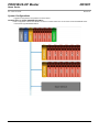
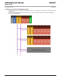
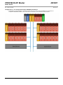
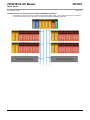
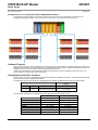
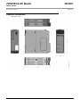
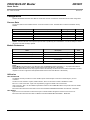
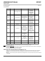
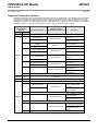
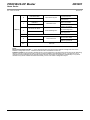
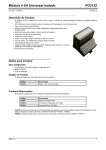
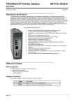
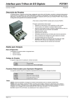
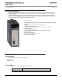
PROFIBUS-DP Master NX5001 Nexto Series Doc. Code: CE114902 Revision: D Product Description Nexto Series is a powerful and complete serie of Programmable Logic Controllers (PLCs) with exclusive and innovative features, targeted for covering control systems requirements from medium to large applications or high performance industrial machines. NX5001 PROFIBUS-DP Master is an advanced PROFIBUS master interface designed to be used together with Nexto Series CPUs. This module allows the access of up to 3584 input bytes and 3584 output bytes. NX5001 also supports redundancy use for application where high availability is expected. Its main features are: PROFIBUS-DP Master communication protocol compatible with any PROFIBUSDP/ DPV1 slave equipment, according to EN 50170, IEC 61158 and IEC-61784 standards Supports up to 125 slaves (using network repeaters) Redundant architecture support Global Control Commands support (Sync, Unsync, Freeze, Unfreeze) Hot swap support Enhanced diagnostics services All configuration and parameterization through MasterTool IEC XE One Touch Diag Electronic Tag on Display LCD and LED for diagnostic indication Baud rate up to 12 Mbits/s Ordering Information Included Items The product package contains the following items: NX5001 module Installation guide Product Code The following code should be used to purchase the product: Code NX5001 Altus S. A. Description PROFIBUS-DP Master 1 PROFIBUS-DP Master NX5001 Nexto Series Doc. Code: CE114902 Revision: D Related Products The following products must be purchased separately when necessary: Code Description PO5063V1 PROFIBUS-DP Fieldbus Head PO5063V5 Redundant PROFIBUS-DP Fieldbus Head PO5064 PROFIBUS-DPV1 Head PO5065 Redundant PROFIBUS-DPV1 Head NX5110 PROFIBUS-DP Fieldbus Head NX5210 Redundant PROFIBUS-DP Fieldbus Head AL-2601 PROFIBUS Connector AL-2602 PROFIBUS Terminator Connector AL-2605 Terminator with Power Supply Diagnostic AL-2303 PROFIBUS cable AL-2431 FOCUS/ PROFIBUS Optical Repeater AL-2432 FOCUS/ PROFIBUS Optical Repeater with Two Ports Notes: PO5063V1: The PROFIBUS-DP Fieldbus Head allows the connection of Ponto Series modules to PROFIBUS fieldbuses, expanding CPU’s I/O system. PO5063V5: The Redundant PROFIBUS-DP Fieldbus Head allows the connection of Ponto Series modules to redundant PROFIBUS fieldbuses. PO5064: The PROFIBUS-DP Fieldbus Head allows the connection of Ponto Series modules to PROFIBUS fieldbuses, expanding the amount of I/O points connected to a given CPU. In addition, PO5064 also supports DPV1 communication between Ponto series modules and any other node from the PROFIBUS fieldbus. PO5065: The Redundant PROFIBUS-DP Fieldbus Head allows the connection of Ponto Series modules to redundant PROFIBUS fieldbuses, expanding the amount of I/O points connected to a given CPU. In addition, PO5065 supports DPV1 communication between Ponto series modules and any other node from the PROFIBUS fieldbus. NX5110: The PROFIBUS-DP Fieldbus Head allows the connection of Nexto Series modules to PROFIBUS fieldbuses, expanding CPU’s I/O system. In addition, NX5110 supports DPV1 communication between Ponto series modules and any other node from the PROFIBUS fieldbus. NX5210: The redundant PROFIBUS-DP Fieldbus Head allows the connection of Nexto Series modules to PROFIBUS fieldbuses, expanding CPU’s I/O system. In addition, NX5210 supports DPV1 communication between Ponto series modules and any other node from the PROFIBUS fieldbus. AL-2601: AL-2601 is a standard DB9 connector with standard PROFIBUS pins. It is suitable for connection to PROFIBUS devices mounted on intermediate positions at the PROFIBUS fieldbus (not on the ends of the PROFIBUS fieldbus). This connector has input and output connection to the fieldbus cable, allowing device exchange without any interruption of data transmission. AL-2602: The termination connector is a standard DB9 connector with standard PROFIBUS pins and termination components internally mounted. It is suitable for connection to PROFIBUS devices mounted on the PROFIBUS fieldbus’ ends. AL-2605: This device is mounted at the ends of the PROFIBUS fieldbus and it replaces AL-2602. AL-2605 was developed to ensure PROFIBUS fieldbus operation even if the modules placed at the PROFIBUS fieldbus’ ends are turned off or removed. The product also verifies field power supply status, delivering its diagnostics in case of failure. It’s recommended for any PROFIBUS-DP fieldbus where reliability and availability are main requirements. AL-2303: Cable for PROFIBUS fieldbus. AL-2431 and AL-2432: Optical repeaters for interconnection of any PROFIBUS devices through fiber optics. AL-2432 has redundancy in optical media, increasing the system availability. Altus S. A. 2 PROFIBUS-DP Master NX5001 Nexto Series Doc. Code: CE114902 Revision: D Innovative Features Nexto Series brings to the user several innovations in utilization, supervision and system maintenance. These features were developed focusing a new experience in industrial automation. The list below shows some new features that the user will find in NX5001 module: One Touch Diag TM: One Touch Diag is an exclusive feature that Nexto Series brings to PLCs. With this new concept, the user can check diagnostic information of any module present in the system directly on CPU’s graphic display with one single press in the diagnostic switch of the respective module. OTD is a powerful diagnostic tool that can be used offline (without supervisor or programmer), reducing maintenance and commissioning times. ETD – Electronic Tag on Display: Another exclusive feature that Nexto Series brings to PLCs is the Electronic Tag on Display. This new functionality brings the process of checking the tag names of any I/O pin or module used in the system directly to the CPU’s graphic display. Along with this information, the user can check the description, as well. This feature is extremely useful during maintenance and troubleshooting procedures. DHW – Double Hardware Width TM: Nexto Series modules were designed to save space in user cabinets or machines. For this reason, Nexto Series delivers two different module widths: Double Width (two backplane rack slots are required) and Single Width (only one backplane rack slot is required). This concept allows the use of compact I/O modules with a high-density of I/O points along with complex modules, like CPUs, fieldbus masters and power supply modules. iF Product Design Award 2012: Nexto Series was the winner of iF Product Design Award 2012 in industry + skilled trades group. This award is recognized internationally as a seal of quality and excellence, considered the Oscars of the design in Europe. Product Features General Features NX5001 Altus S. A. Backplane rack occupation 2 sequential slots Maximum amount of PROFIBUS slaves 125 Maximum amount of cyclic input bytes per slave 244 Maximum amount of cyclic output bytes per slave 244 Maximum amount of cyclic input bytes 3584 Maximum amount of cyclic output bytes 3584 PROFIBUS-DP Yes Baud rate 9.6 to 12,000 Kbit/s, configurable Redundancy support Yes (software version 1.1.0.0 or above/ product review AE or above) Global Control Commands support Yes (software version 1.2.0.6 or above / product revision AD or above) Hot swap support Yes Status and diagnostic indication Display, LEDs, web pages and CPU’s internal memory One Touch Diag (OTD) Yes Electronic Tag on Display Yes 3 PROFIBUS-DP Master NX5001 Nexto Series Doc. Code: CE114902 Revision: D Isolation PROFIBUS interface to logic PROFIBUS interface to 1000 Vac / 1 minute Protective earth 1000 Vac / 1 minute Logic to protective earth 1250 Vac / 1 minute Current consumption from backplane rack power supply 400 mA Power dissipation 2W IP level IP 20 Operating temperature 0 to 60 °C Storage temperature -25 to 75 °C Operating and storage relative humidity 5 to 96 %, non-condensing Conformal coating Yes IEC 61131-2 CE, Electromagnetic Compatibility (EMC) and Low-Voltage Directive (LVD) Standards Module dimensions (W x H x D) 36.00 x 114.63 x 115.30 mm Package dimensions (W x H x D) 44.00 x 122.00 x 147.00 mm Weight 200 g Weight with package 250 g Notes: Baud rate: Baud rate can be configured with the following communication speeds: 9.6 kbits/s, 19.2 kbits/s, 93.75 kbits/s, 187.5 kbits/s, 500 kbits/s, 1,500 kbits/s, 3,000 kbits/s, 6,000 kbits/s and 12,000 kbits/s. Redundancy support: It’s possible to design a PROFIBUS redundant fieldbus using two NX5001. This implementation is described in the section System Configurations. Global Control Command Support: This service aims to synchronize inputs and / or outputs of a given group of PROFIBUS slaves through the Sync, Unsync, Freeze and Unfreeze commands. These commands are available on PROFIBUS-DP NX5001 master, via User Commands. The description of this service lies in the manual PROFIBUS-DP NX5001 (MU214601), Appendix C - Global Control Commands. See also Compatibility section of Appendix C, to get more details about the availability of this service and associated products (NX5001 and the MasterTool IEC XE programmer). Maximum number of PROFIBUS slaves: NX5001 can address up to 31 slaves without repeaters and media converters. In case of more than 31 slaves, repeaters and media converters must be used. Logic: Logic is the name for the internal interfaces such as processors, memories and backplane rack interfaces. Conformal coating: Conformal coating protects the electronic components inside the product from moisture, dust and other harsh elements to electronic circuits. ATTENTION: The Global Control Commands are incompatible with support for network redundancy. So they are invalid for architectures such as those described in the next section: - Configuration B: Redundant PROFIBUS Fieldbus - Configuration D: Two Independent Redundant PROFIBUS Fieldbuses This and other information can be found in MU214601, Appendix C - Global Control Commands. Altus S. A. 4 PROFIBUS-DP Master NX5001 Nexto Series Doc. Code: CE114902 Revision: D System Configurations Suggested configurations using NX5001 are shown below: Configuration A: Simple PROFIBUS Fieldbus Basic configuration contains one NX5001 connected to a Nexto Series CPU on the same rack and PROFIBUS slaves connected through PROFIBUS fieldbus. Altus S. A. 5 PROFIBUS-DP Master NX5001 Nexto Series Doc. Code: CE114902 Revision: D Configuration B: Redundant PROFIBUS Fieldbus Configuration B has one redundant PROFIBUS fieldbus. In this case, two NX5001 are connected to a Nexto Series CPU on the same rack. The redundant PROFIBUS fieldbus endures a failure in one of the two redundant fieldbuses, offering more availability, required in critical applications. Altus S. A. 6 PROFIBUS-DP Master NX5001 Nexto Series Doc. Code: CE114902 Revision: D Configuration C: Two Independent Simple PROFIBUS Fieldbuses Configuration C has two NX5001 connected to a Nexto CPU on the same rack. Each NX5001 is connected to an independent PROFIBUS fieldbus. In this case there’s no redundancy. The architecture is shown below. Altus S. A. 7 PROFIBUS-DP Master NX5001 Nexto Series Doc. Code: CE114902 Revision: D Configuration D: Two Independent Redundant PROFIBUS Fieldbuses Configuration D is the most complex configuration supported by Nexto Series. It is the redundant version of configuration C. As shown in the picture below, there are two independent redundant PROFIBUS fieldbuses. Altus S. A. 8 PROFIBUS-DP Master NX5001 Nexto Series Doc. Code: CE114902 Revision: D Configuration E: Four Independent Simple PROFIBUS Fieldbuses Configuration E has four NX5001 connected to a Nexto CPU on the same rack. Each NX5001 is connected to an independent PROFIBUS fieldbus. In this case there’s no redundancy. The architecture is shown below. Software Features Nexto Series brings to the user the MasterTool IEC XE, a powerful tool that provides a complete interface for programming all Nexto Series’ modules. This means that there is no additional software required to configure the PROFIBUS slaves. All settings are done in the same software used for programming Nexto CPUs. Another important feature is that all PROFIBUS slaves parameterization are sent to NX5001 through Nexto CPU, so it doesn’t require any special cable for its configuration. Compatibility with Other Products NX5001 doesn’t have any incompatibility with Nexto Series Modules and MasterTool IEC XE. The following table describes the main Altus’ products compatible with NX5001. The table below show information about compability between NX5001 and MasterTool IEC XE tool of Nexto Series. Compatible Software Version NX5001 Versão 1.2.0.6 Revision Feature MasterTool IEC XE AP Global Control Command (Sync/Freeze) 2.01 or higher The table below indicates the compatibility of the main Altus products with NX5001 module. Altus S. A. Software version Product revision PO5063 1.35 or higher DS or higher PO5063V1 2.07 or higher AV or higher PO5064 1.02 or higher AI or higher PO5063V5 5.07 or higher AV or higher PO5065 1.02 or higher AI or higher PO5063V4 4.35 or higher AU or higher NX5110 1.0.0.12 AD or higher NX5210 1.0.0.12 AD or higher 9 PROFIBUS-DP Master NX5001 Nexto Series Doc. Code: CE114902 Revision: D Physical Dimensions Dimensions in mm. Altus S. A. 10 PROFIBUS-DP Master NX5001 Nexto Series Doc. Code: CE114902 Revision: D Installation Electrical Installation The figure bellow illustrates the electrical installation of the PROFIBUS-DP Master NX5001 installed in a Nexto rack. Diagram Notes: 1 – Standard interface for connection to PROFIBUS fieldbus. Pin 1 of DB9 connector is connected to the protective earth signal from Nexto backplane rack. 2 – Use the AL-2303 cable to the PROFIBUS fieldbus and one of the following connectors: AL-2601 is a connector without internal termination for PROFIBUS fieldbus and can be used to connect any PROFIBUS module in a position where termination is not required. AL-2602 is a connector with internal termination for PROFIBUS fieldbus. It must be used in PROFIBUS fieldbus modules located at PROFIBUS fieldbus ends. Altus also offers a second option to cover requirements where reliability and availability are the main requirements. For these cases, AL-2605 must be placed in each PROFIBUS fieldbus ends and all PROFIBUS modules must use connectors without internal termination, such as AL2601. More information about AL-2605 can be found at AL-2605 Characteristic Information - CE104705. It’s mandatory to use always two PROFIBUS fieldbus terminations. Each termination must be placed at each PROFIBUS fieldbus end. 3 – The module is connected to earth through the Nexto Series backplane racks. 4 – NX5001 is powered by the Nexto Series power supply connected on the same backplane rack. NX5001 doesn’t require any other external power supply. Mechanical Assembly The mechanical mounting of this module is described at Nexto Series User Manual – MU214600. There is no particular issue on the installation of this module. Altus S. A. 11 PROFIBUS-DP Master NX5001 Nexto Series Doc. Code: CE114902 Revision: D Configuration NX5001 PROFIBUS-DP Master User Manual - MU214601 must be consulted for information about module configuration. Process Data The process data are the variables used for access and module control. The table below contains all variables used by NX5001. Process data Description Type Update User Command - Byte 0 Enables or disables the module features %QB (Read/ Write) Always User Command - Byte 1 Reserved for internal use %QB (Read/ Write) Always Reserved Reserved for internal use %IB (Read) Always Global Control Command - Status Global Control Command’s Status %IB (Read) Always Reserved Reserved for internal use %IW (Read) Always Note: Update: This field indicates if the respective process data is updated by CPU and NX5001. If it is set as Always, it means that the process data is always updated. Module Parameters Name Description Standard value %Q Start Address of Module Diagnostics Area Defines the start address of the module diagnostics. - %Q Start Address of Slave Diagnostics Area Defines the start address of the slave diagnostics. - Net Redundancy Enables or disables the PROFIBUS net redundancy. False Failure Mode Enables or disables the switchover in case of module failure. True Use Specific Diagnostics to Slave Indicates if it uses the specific diagnostics to slave False Notes: Failure Mode: This parameter is only valid when there is PROFIBUS master redundancy, i.e. in projects where there is half-cluster redundancy (further details on Nexto Series CPUs User Manual – MU214605). Standard value: MasterTool IEC XE programmer fills it automatically, but allows the user to edit its initial offset. The limit depends on the CPU supported model (details at Nexto Series CPUs User Manual – MU214605). Utilization User Commands The NX5001 module provides two control variables (User Command Byte-0 and User Command Byte 1) for user command. The bit 0 of User Command - Byte 0, Enable Interface, which can be used to enable or disable the master. Bits 4 to 7 of User Command – Byte 0 are responsible by trigger the Global Control Commands. User Command – Byte 1 it’s the variable responsible to define for each PROFIBUS Slave Groups will receive the Global Control Commands. More information about User Commands can be found at NX5001 PROFIBUS-DP Master User Manual – MU214601. User Status Bytes 0.2 and 3 are reserved for internal use. Byte 1 indicates whether the global command can be sent or not. More information about the User stats is in Master User Manual PROFIBUS-DP NX5001 - MU214601. Altus S. A. 12 PROFIBUS-DP Master NX5001 Nexto Series Doc. Code: CE114902 Revision: D Maintenance Altus recommends that all module’s connections be checked and that all dust or any kind of dirt at the module’s enclosure be removed at least every 6 months. NX5001 offers five important features to assist the user during maintenance: Electronic Tag on Display, One Touch Diag, Status and Diagnostics Indicators, web page with complete status and diagnostics list and status and diagnostics mapped to internal memory. Electronic Tag on Display and One Touch Diag Electronic Tag on Display and One Touch Diag are important features that provides for the user the option to check the tag, description and diagnostics related to a given module directly on the CPU display. Electronic Tag on Display and One Touch Diag are easy-to-use features. To check the tag and diagnostics of a given module, it’s required only one short press (shorter than 1 s) on its diagnostic switch. After pressing once, CPU will start to scroll tag information and diagnostic information of the module. To access the respective description for the module just long press (longer than 1 s) the diagnostic switch of the respective module. More information about Electronic Tag on Display can be found at Nexto Series User Manual – MU214600. Status and Diagnostic Indicators All Nexto slave modules have a display with the following symbols: D, E, 0, 1 and numeral characters. The states of the symbols D, E, 0, 1 are common for all Nexto series slave modules, these states can be consulted in the table below. The meaning of the numeral characters can be different for specific modules. NX5001 doesn’t use these segments. NX5001 also has two LEDs used to indicate diagnostics related to the PROFIBUS interface. ST and ER LEDs The PROFIBUS-DP Master NX5001 has two LEDs at the front panel to indicate the diagnostics of PROFIBUS interface. The table below describes the meaning of each LED state. ST LED Altus S. A. ER LED Description Cause Module off No Power supply. Hardware failure Off Off On Off Communication with slaves was established Communication with all slaves was established. On Blinking intermittent There are present and absent slaves in the PROFIBUS fieldbus Some PROFIBUS slaves are exchanging I/O with the Master NX5001, others aren’t. Error in PROFIBUS termination. Off On No activity in the PROFIBUS fieldbus Loss of communication with all slaves. PROFIBUS cable isn’t connected. PROFIBUS cable is defective. Error in PROFIBUS termination. Blinking intermittent Off NX5001 received configuration The Master NX5001 received the settings from CPU, but the communication hasn’t been released by the application. Configuration has no slaves declared NX5001 is operating in Passive mode Blinking 4x Off NX5001 is not configured NX5001 didn’t receive the slave’s settings and PROFIBUS fieldbus settings from CPU. On On NX5001 initialization The Master NX5001 was connected to the bus or restarted. Hardware failure 13 PROFIBUS-DP Master NX5001 Nexto Series Doc. Code: CE114902 Revision: D D and E States D E Description Causes Solution Priority Check if the module is completely connected to the rack and if the rack is supplied by an external power supply - Off Off Display fail or module off - On Off Normal use - Blinking 1x Off Active Diagnostic 9 (Lowest) There is at least one active diagnostic related to the module NX5001 Check which is the active diagnostic. More information can be found at Maintenance section of this document 8 Check if CPU is in RUN mode. More information can be found on CPU’s documentation 7 Blinking 2x Off CPU in STOP mode - Blinking 3x Off Reserved - 6 Check the module Failure in some hardware or Blinking 4x Off Non fatal fault software component, which does not have impact on the basic functionality of the product Off Off Blinking 1x Blinking 2x Parameterization error NX5001 isn’t parameterized or didn’t receive the new parameterization Loss of master Loss of communication between module and CPU diagnostic information. If it is a hardware fault, provide the replacement of 5 this part. If it is a software fault, please contact the Technical Support 4 Check if the module is completely connected to the backplane rack 3 Check if CPU is in RUN mode Off Blinking 3x Reserved - 2 Off Blinking 4x Fatal hardware fault - 1 (Highest) Note: Fatal hardware fault: Please contact Altus support team in case of fatal hardware fault. 0, 1 and Numeral Characters The segments 0 and 1 should be normally off. These two segments will start to blink when the module is on the Diagnostic Mode (Electronic Tag on Display and One Touch Diag). The Numeral Characters aren’t used in this module. Web Page with Complete Status and Diagnostic List Another way to access diagnostic information on Nexto Series is via web pages. Nexto Series CPU’s has an embedded web pages server that provides all Nexto status and diagnostic information, which can be accessed using a simple browser. More information about web page with complete status and diagnostic list can be found at Nexto Series CPUs User Manual – MU214605. Altus S. A. 14 PROFIBUS-DP Master NX5001 Nexto Series Doc. Code: CE114902 Revision: D Diagnostics Mapped to Variables All NX5001’s diagnostics can be accessed through variables that can be handled by the user application or even forwarded to a supervisory system using a communication channel. There are two different ways to access diagnostics in the user application: using symbolic variables with AT directive or addressing memory. Altus recommends use symbolic variables for diagnostic accessing. The table below shows all available diagnostics for NX5001 and their respective memory address, description, symbolic variable and string that will be shown on the CPU graphical display and web. Direct Representation Variable Variable Bit %QB(n) 0..7 0 Diagnostic Message Symbolic Variable DG_modulename.tGeneral. Reserved MODULE W/ DIAGNOSTICS bActiveDiagnostics NO DIAG 1 MODULE W/ FATAL ERROR bFatalError CONFIG. MISMATCH bConfigMismatch 2 WATCHDOG ERROR 3 bWatchdogError OTD SWITCH ERROR bOTDSwitchError - bBusCommunicationError 6..7 Reserved %QB(n+2) 0..7 Reserved %QB(n+3) 0..7 Reserved 0 Reserved ABSENT CONFIG 1 TRUE – Fatal error TRUE – Parameterization error FALSE – Parameterization ok TRUE – Watchdog has been detected TRUE – Module’s OTD switch failure FALSE – OTD switch ok - 5 FALSE – Module doesn’t have active diagnostic FALSE – No watchdog 4 TRUE – Module has active diagnostics FALSE – No fatal error - %QB(n+1) Description bNX5001NoCfg TRUE – Error in bus communication FALSE – No error in bus communication TRUE – NX5001 didn’t receive the configuration from CPU FALSE – NX5001 received CPU configuration Reserved 2..3 %QB(n+4) 4 - bStsEnableInterface TRUE - NX5001 is enabled by user command FALSE – NX5001 was disabled by user command Reserved 5 TRUE – Master redundancy is enabled (control operand) 6 7 Altus S. A. - bStsMstRedundEnable FALSE –Master redundancy is not enabled (control operand) Reserved 15 PROFIBUS-DP Master NX5001 Nexto Series Doc. Code: CE114902 Revision: D 0 PB SLAVE UNCONFIGURED bSlaveNotConfigured - 1 PB SLAVE NOT PRESENT bSlaveNotPresent PB SLAVE W/ DIAG. %QB(n+5) 2 bSlaveWithDiagnostic - FALSE – All slaves are parameterized TRUE – At least one absent slave in the fieldbus FALSE – All slaves are present in the fieldbus TRUE – At least one slave with active diagnostics FALSE – No slaves with active diagnostics Reserved 3..4 COMM. FAILURE bPbusCommFail 5 6..7 TRUE – At least one slave isn’t parameterized TRUE – PROFIBUS communication failed FALSE – PROFIBUS fieldbus is operational Reserved Notes: Direct Representation Variable: “n” is the address defined in the field %Q Start Address of Diagnostic Area on the NX5001’s configuration screen – Modules Parameters tab in the MasterTool IEC XE. Symbolic Variable: Some symbolic variables serve to access diagnostics. This diagnostics are stored into the addressing memory, then the AT directive is used to map the symbolic variables in the addressing memory. The directive AT is a reserved word in the MasterTool IEC XE that uses this directive to declares the diagnostics automatically on a symbolic variables. All symbolic variables declared automatically can be found inside of Diagnostics object. Altus S. A. 16 PROFIBUS-DP Master NX5001 Nexto Series Doc. Code: CE114902 Revision: D Manuals For correct application and utilization NX5001 PROFIBUS-DP Master User Manual - MU214601 must be consulted. For further technical details, configuration, installation and programming of Nexto Series, the table below should be consulted. The table below is only a guide of some relevant documents that can be useful during the use, maintenance, and programming of NX5001. The complete and updated table containing all documents of Nexto Series can be found at Nexto Series User Manual – MU214600. Document Code Description Language CE114000 CT114000 CS114000 Nexto Series – Technical Characteristics Série Nexto – Características Técnicas Serie Nexto – Especificaciones y Configuraciones English Portuguese Spanish MU214600 MU214000 MU214300 Nexto Series User Manual Manual de Utilização Série Nexto Manual Del Usuario Nexto English Portuguese Spanish MU214601 MU214001 MU214301 NX5001 PROFIBUS-DP Master User Manual Manual de Utilização Mestre PROFIBUS-DP NX5001 Manual del Usuario Maestro PROFIBUS-DP NX5001 English Portuguese Spanish MU214605 MU214100 MU214305 Nexto Series CPUs User Manual Manual de Utilização UCPs Série Nexto Manual del Usuario UCPs Serie Nexto English Portuguese Spanish MU299609 MU299048 MU299800 MasterTool IEC XE User Manual Manual de Utilização MasterTool IEC XE Manual del Usuario MasterTool IEC XE English Portuguese Spanish MU299026 Manual de Utilização da Rede PROFIBUS Portuguese MU209010 Configuração da Remota PROFIBUS – Série Ponto Portuguese MU209508 Manual de Utilização Cabeça PROFIBUS PO5063V1 e Cabeça Redundante PROFIBUS PO5063V5 Portuguese MU219511 MU209511 Altus S. A. PO5064 PROFIBUS Head and PO5065 Redundant PROFIBUS Head Utilization Manual Manual de Utilização Cabeça PROFIBUS PO5064 e Cabeça Redundante PROFIBUS PO5065 English Portuguese MU209020 Manual de Utilização Rede HART sobre PROFIBUS Portuguese MU204631 Manual de Utilização do Repetidor Ótico / FOCUS PROFIBUS Portuguese 17