1
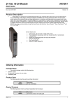
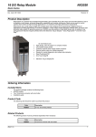
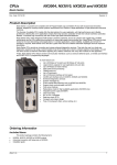
Technical Characteristics Doc Code: CE114000 Nexto Series Revision: F Nexto Series Programmable Logic Controller Nexto Series is a powerful and complete Programmable Logic Controllers (PLCs) series with exclusive and innovative features, targeted for covering control systems requirements from medium to large applications or high performance industrial machines. Nexto Series architecture provides a wide range of input and output modules. These modules, combined with a powerful 32-bit processor and a high-speed-Ethernet-based backplane, cover many user applications, such as high-speed machinery control, complex distributed and redundant process applications or even large I/O systems for building automation. Besides, it delivers modules for motion control, communication and interfaces to the most popular fieldbuses, among other features. Nexto Series architecture uses a state-of-the-art high-speed Ethernet backplane bus technology, which allows input, output and processed information to be shared among all modules within the system. The I/O modules can be easily distributed in the field. It can be used local as well as remote I/Os without any loss in performance. In addition, Nexto Series brings a complete tool for programming, configuration, simulation and debugging user application: MasterTool IEC XE. MasterTool IEC XE is flexible and easy to use software that provides the six programming languages defined by IEC 61131-3 standard: Structured Text (ST), Sequential Function Chart (SFC), Function Block Diagram (FBD), Ladder Diagram (LD), Instruction List (IL) and Continuous Function Chart (CFC). MasteTool IEC XE allows the use of different languages on the same application, providing to the user a powerful way to organize the application and to reuse codes used in previous applications. This document is an introduction to the general features of Nexto Series. For further information, please refer to the specific manual or technical document of each product. Altus S. A. 1 Technical Characteristics Nexto Series Doc Code: CE114000 Revision: F Module List Below is the complete list of modules. Please contact your sales representative to check availability and lead times. For further information, please refer to the product documentation of each module. CPUs – Central Processing Units NX3004: CPU with 1 Ethernet port, 1 serial channel, remote rack expansion support and integrated power supply NX3010: High-speed CPU, 1 Ethernet port, 2 serial channels, memory card interface and remote rack expansion support NX3020 : High-speed CPU, 2 Ethernet ports, 2 serial channels, memory card interface and remote rack expansion support NX3030 : High-speed CPU, 2 Ethernet ports, 2 serial channels, memory card interface, remote rack expansion and redundancy support Power Supply Modules NX8000 : 30 W 24 Vdc Power Supply Module Racks NX9000: 8-Slot Backplane Rack NX9001 : 12-Slot Backplane Rack NX9002 : 16-Slot Backplane Rack NX9003 : 24-Slot Backplane Rack NX9010: 8-Slot Backplane Rack (No Hot Swap) Special Modules Fieldbus Interfaces NX5000 : Ethernet Module NX5001 : PROFIBUS-DP Master NX5110: PROFIBUS-DP Head NX5210: Redundant PROFIBUS-DP Head Input Modules NX1001 : 24 Vdc 16 DI Module NX6000 : 8 AI Voltage/Current Module NX6010 : 8 AI Thermocouple Module NX6020 : 8 AI RTD Module Mixed I/O Modules NX1005 : 24 Vdc 8 DO Transistor / 8 DI Mixed Module NX4000 : Bus Expansion Module NX4010 : Redundancy Link Module Software MT8500: MasterTool IEC XE LITE MT8500: MasterTool IEC XE BASIC MT8500: MasterTool IEC XE ADVANCED MT8500: MasterTool IEC XE PROFESSIONAL Accessories NX9100 : Left/Right Side Rack Ends NX9102: Rack Connector Cover NX9401: 6-Terminal Connector NX9402: 10-Terminal Connector with Cable Guides NX9403: 20-Terminal Connector with Cable Guides NX9404: 6-Terminal Connector with fixing Output Modules NX2001 : 24 Vdc 16 DO Transistor Module NX2020 : 16 DO Relay Module NX6100 : 4 AO Voltage/Current Module Altus S. A. 2 Technical Characteristics Doc Code: CE114000 Nexto Series Revision: F Innovative Features Nexto Series brings to the user several innovations in utilization, supervision and system maintenance. These features were developed focusing a new experience in industrial automation. The list below shows some new features that users will find in the Nexto Series: Battery Free Operation: Nexto Series does not require any kind of battery for memory maintenance and real time clock operation. This feature is extremely important because it reduces the system maintenance needs and allows the use in remote locations where maintenance can be difficult to be performed. Besides, this feature is environmentally friendly. Easy Plug System: Nexto Series has an exclusive method to plug and unplug I/O terminal blocks. The terminal blocks can be easily removed with a single movement and with no special tools. In order to plug the terminal block back to the module, the frontal cover assists the installation procedure, fitting the terminal block to the module. Multiple Block Storage: Several kinds of memories are available to the user in Nexto Series CPUs, offering the best option for any user needs. These memories are divided in volatile memories and non-volatile memories. For volatile memories, Nexto Series CPUs offer addressable input (%I), addressable output (%Q), addressable memory (%M), data memory and redundant data memory. For applications that require non-volatile memory functionality, Nexto Series CPUs bring retain addressable memory (%M), retain data memory, persistent addressable memory (%Q), persistent data memory, program memory, source code memory, UCP file system (Doc, pdf, data) and memory card interface. One Touch Diag TM: One Touch Diag is an exclusive feature that Nexto Series brings to PLCs. With this new concept, user can check diagnostic information of any module present in the system directly on CPU’s graphic display with one single press in the diagnostic switch of the respective module. OTD is a powerful diagnostic tool that can be used offline (without supervisor or programmer), reducing maintenance and commissioning times. OFD – On Board Full Documentation: Nexto Series CPUs are capable of storing the complete project documentation in its own memory. This feature can be very convenient for backup and maintenance purposes, since the complete information is stored in a single and reliable place. ETD – Electronic Tag on Display: Another exclusive feature that Nexto Series brings to PLCs is the Electronic Tag on Display. This new functionality makes the process of checking the tag names of any I/O point or module used in the system directly on the CPU’s graphic display. Along with this information, user can check the description, as well. This feature is extremely useful during maintenance and troubleshooting procedures. DHW – Double Hardware Width TM: Nexto Series modules were designed to save space in user cabinets or machines. For this reason, Nexto Series delivers two different module widths: Double Width (two backplane rack slots are required) and Single Width (only one backplane rack slot is required). This concept allows the use of compact I/O modules with a highdensity of I/O points along with complex modules, such as CPUs, fieldbus masters and power supply modules. High-Speed CPU: All Nexto Series CPUs were designed to provide an outstanding performance to the user, allowing the coverage of a large range of applications requirements. For example: Nexto CPUs can execute sum, multiplication and subtraction instructions in less than 15 ns for integer type values and in less than 23 ns for real type values. Nexto CPUs are able to perform 1,000 PIDs loops in less than 5 ms. iF Product Design Award 2012: Nexto Series was the winner of iF Product Design Award 2012 in industry + skilled trades group. This award is recognized internationally as a seal of quality and excellence, considered the Oscars of the design in Europe. Altus S. A. 3 Technical Characteristics Doc Code: CE114000 Nexto Series Revision: F Architecture Nexto Series is capable of addressing many different applications ranging from small high-speed machinery automation to large complex process automation. For this reason, the system is very flexible and modular, enabling many different configurations without compromising cost and performance. The architecture is divided in the following main components: CPU The CPU is responsible for the execution of all logic and control functions. The basic CPU cycle is composed by: reading inputs, running application algorithms and logic, writing outputs and providing communication processes with the supervision system and fieldbus networks. Power Supply Module (PSU) The Power Supply Module provides power to the modules installed on the backplane racks. Each rack must have its own Power Supply Module. The application power requirements are shown in the configuration tool. Backplane Bus A typical system consists of a local rack (CPU and its local I/O modules) and remote racks (sets of remote I/O modules). For the local rack, Nexto Series architecture delivers a state-of-the-art high-speed real-time 100 Mbps Ethernet backplane bus technology. Since it is Ethernet based, the local rack bus can be easily expanded to remote racks using standard Ethernet cables (up to 100 m) and devices called Bus Expansion Modules. These devices convert the internal signals to the standard Ethernet 100BASE-TX media. Bus Expansion can be used in redundant mode to obtain an extremely reliable architecture. Every rack can have up to 24 modules and the system can address up to 25 racks. Backplane Racks The backplane racks have special aluminum chassis with a backplane board where all modules are connected. They are assembled directly to the panel and deliver high immunity against EMI and ESD (if the recommended grounding rules are performed during installation phase). I/O Modules The I/O modules are plugged into the racks to activate the different types of field signals and their interface to the CPU or fieldbus heads. Nexto Series supports a wide variety of I/O types and operating ranges, thus covering all the typical needs for an automation system. The modules are hot swappable, meaning that they can be unplugged without turning the system off or removing the power. Due to isolation features, some I/O modules must be supplied by external power supplies. Fieldbus Head The fieldbus heads connect Nexto Series modules to different fieldbus networks. They can communicate with CPUs from different vendors, supporting several protocols such as PROFIBUS-DP. Fieldbus Interface The fieldbus interfaces are fieldbus master nodes and allow the access to remote modules or other equipment based on major industry fieldbus, such as PROFIBUSDP, MODBUS and others. The fieldbus interfaces are plugged into local racks and require two slots. Altus S. A. 4 Technical Characteristics Doc Code: CE114000 Nexto Series Revision: F Application Examples Compact CPU This architecture explores the compact application needs, one CPU NX3004 with integrated power supply, 8-Slot backplane rack and input and output modules allow the space and cost reduction in your project. This architecture is intended for use in machinery automation. Single CPU This architecture is based on a single rack, called base rack. This rack is populated with a CPU, a power supply module (PSU) and the required I/O modules for the application, as shown below. The modules order must follow the configuration rules presented in the configuration tool. This architecture is intended for use in small applications. Altus S. A. 5 Technical Characteristics Doc Code: CE114000 Nexto Series Revision: F Single CPU with Remote Rack Expansion This architecture is based on a base rack (where the CPU is placed) and remote racks. The communication between the base rack and remote racks is done via the Bus Expansion module. Each remote rack needs its own power supply module (PSU) and a Bus Expansion module. Each Bus Expansion module can be located 100 m far from the other using standard shielded CAT5 Ethernet cables. The Bus Expansion modules have two RJ45 ports, where one port is for incoming data and another one for outgoing data. In this application example, the base rack’s Bus Expansion module is connected using only one cable and leaving the incoming data port open. The last remote rack has the outgoing data port open. The remote racks between them will have both ports connected: one port connected to the previous rack and the other to the next rack. Each Bus Expansion module has a switch for selecting the rack address. Each rack must have a unique address. This architecture is intended for medium to large applications, where the number of I/O points is high. Altus S. A. 6 Technical Characteristics Doc Code: CE114000 Nexto Series Revision: F Single CPU with Remote Rack Expansion and Loopback Cable This architecture is based on the previous one with a base rack (where the CPU is placed) and remote racks. The communication between the base rack and remote racks is done via the Bus Expansion modules. The only difference is that the outgoing data port in the last remote rack Bus Expansion module is connected to the base rack Bus Expansion module incoming data port. This architecture allows the system to keep the I/O access even in the case of a single failure on extension cables. The CPU will detect the damaged cable, re-route the internal data paths to override this failure and generate user diagnostics. This feature is interesting for fast maintenance with the system powered on and it increases the overall system availability. This architecture is intended for medium to large applications, where the number of I/O points is high and there is the need of higher availability. Altus S. A. 7 Technical Characteristics Doc Code: CE114000 Nexto Series Revision: F Single CPU with Redundant Rack Expansion and Loopback Cable This architecture is based on the use of two Bus Expansion modules in the racks. With two Bus Expansion modules, the system has an outstanding availability, because it supports expansion cable failure or Bus Expansion module failure. Just as the previous architecture, this is intended for systems where maintenance is an issue and the system must be available for a longer time. In this architecture, the racks must be mounted as the following diagram, where the Bus Expansion modules are located side by side on the last slot positions. Besides, there are unused Bus Expansion ports that must be left unconnected. Altus S. A. 8 Technical Characteristics Doc Code: CE114000 Nexto Series Revision: F Fieldbus Interfaces This architecture is based on the use of fieldbus interfaces to access networks for distributing remote I/Os and other thirdparty devices. Fieldbus Interfaces with Redundancy This architecture is based on the previous one with the difference of using two fieldbus interfaces for accessing the same network. Since it has two interfaces, the network is redundant, providing a system with higher availability. Altus S. A. 9 Technical Characteristics Doc Code: CE114000 Nexto Series Revision: F CPU Redundancy For critical applications, Nexto Series supports redundancy of CPUs. The only CPU model with this feature is NX3030. These CPUs can be located in different racks (known as half-clusters). In this architecture, the system will have one controller running the control task (primary controller) and another one acting as the stand-by controller with all current system status for automatic switchover (event where the standby CPU becomes the active one) in case of a primary controller failure. This means that critical processes are not affected by control system hardware failures. The results are: an increased productivity, a minimized downtime and low maintenance times. At the center of a two half-cluster redundant system, there is a pair of redundant CPUs. The redundancy links – between the two CPUs – have two channels, so single failures on each channel will not affect system performance. The Active CPU executes the user application and controls the remote I/Os. The Stand-by CPU is a background resource, ready to take over if necessary. The stand-by CPU is connected to the active CPU via a high-speed link present on a module called Redundancy Link Module. This module must be placed at the right side of the CPU. The CPU and the Redundancy Link module must be placed in certain slots in the racks (which support this functionality). In the event of an unexpected failure affecting the active CPU, the stand-by system switches over automatically, changing execution of the application program and control of the I/Os over to the stand-by CPU, with an up-to-date data context. Once they had switched over, the stand-by CPU becomes the active CPU. Configuration of both systems shall be identical. CPU modules will be placed at identical slots in each half-cluster. After power on, one of the CPUs operates as active and the other CPU enters stand-by mode. Active CPU will update the system status of stand-by CPU at the end of every scan, so the stand-by CPU is always updated with the latest I/O status and results of program execution in the active CPU. This application is easy to set up, with no special programming or parameterization needed by the user. CPU Redundancy & Network Interface Modules As shown in the previous diagram, this architecture has interface network modules with protocols based on Ethernet. There are two network interfaces for each purpose: a control network for CPU to CPU communication and a supervision network for SCADA and OPC usage. Both half-clusters must have two interfaces for each network to form a full redundant system with CPU, network interface and physical media redundancy. Altus S. A. 10 Technical Characteristics Doc Code: CE114000 Nexto Series Revision: F Dimensions The main modules’ dimensions are shown below, in mm. Racks 8-Slot Backplane Rack (No Hot Swap) 8-Slot Backplane Rack Altus S. A. 11 Technical Characteristics Doc Code: CE114000 Nexto Series Revision: F 12-Slot Backplane Rack 16-Slot Backplane Rack Altus S. A. 12 Technical Characteristics Doc Code: CE114000 Nexto Series Revision: F 24-Slot Backplane Rack Modules There are different module sizes in Nexto Series, depending on module type. 18-mm I/O Module This module size is used in 24 Vdc digital input modules, 24 Vdc digital transistor output modules and analog modules. Altus S. A. 13 Technical Characteristics Nexto Series Doc Code: CE114000 Revision: F 36-mm I/O Module This module size is used in digital relay output modules. CPU, Fieldbus Interfaces, Special and Power Supply Modules This module size is used by all remaining modules in Nexto Series. The picture illustrates a NX3030 CPU. Altus S. A. 14 Technical Characteristics Doc Code: CE114000 Nexto Series Revision: F Main Features CPUs The CPUs have many integrated functions, online programming, high memory capacity and many serial channels. These devices are powered by latest 32-bit CPUs allowing outstanding performance and integration of many features. Even the simplest CPU version has an Ethernet port for programming, use in MODBUS TCP networks and embedded web server. The NX3010, NX3020 and NX3030 CPUs have a memory card slot, besides two serial interfaces and the NX3004 CPU have one serial interface for connecting local HMIs and MODBUS networks. The NX3004, NX3010, NX3020 and NX3030 CPUs have web pages with complete status and diagnostic list, firmware update among other features Nexto Series CPUs owns SNTP functionality (Simple Network Time Protocol) to synchronize the clock through Ethernet network. Modules The modules carry high density I/Os. Nexto Series delivers two module form factors – slim and full size modules – allowing the best I/O combination for many applications where high-density and reduced panel size are required. Every I/O module has a display for local diagnostics, where each I/O point state is presented. There is also multifunctional diagnostics about the module status. All diagnostics information is also accessible remotely by CPU, fieldbus head or by MasterTool IEC XE configuration tool. The I/O modules have labels where the user can identify the modules and the terminal blocks. High-Speed Backplane Bus Nexto Series architecture has a state-of-the-art Ethernet based backplane bus. The high throughput enables the update of large quantities of inputs in a short time window. Besides, time critical applications such as motion control are possible with this technology. The modules are addressed and identified automatically, avoiding errors during application setup and field maintenance. The NX9000, NX9001, NX9002 and NX9003, backplane bus provide special features in order to allow CPU redundancy different racks using the Redundancy Link Modules: Automatic module addressing and identification Hot swapping (except NX9010) 100 Mbps Ethernet-based serial bus Extremely accurate time synchronization for I/O update Single chip hardware solution Terminal Block Insertion & Removal Nexto Series has an innovative and patented mechanism for inserting and extracting the I/O modules terminal blocks. In many automation applications, the density of I/Os is high, making the field wiring complicated and unfriendly. When maintenance is needed, the difficulties are even worse, because reaching the wires most times is not an easy job. Sometimes, it’s necessary to unmount some enclosed modules to access the desired ones. In Nexto Series, these problems were solved by combining a special connector shape with a front cover. Besides the easy removal and insertion of terminal blocks, the design makes the panel look nice and organized. Rugged Design Nexto Series delivers an extremely rugged design allowing the use in applications where mechanical vibration is present. Transportation applications or moving places are examples that require this feature. The whole product design was developed in such a way to deliver this feature without compromising the installation and maintenance procedures. Hot Swapping The hot swapping feature allows module replacement without the need of shutting the system down (power off). The CPU keeps controlling the whole process and the modules can be replaced whenever needed. High Availability Nexto Series delivers several different redundant architectures, where CPUs, PSUs and fieldbus interfaces can be mounted in a redundant application. With this flexibility, the system can be tailored from simple systems with no redundancy at all to very complex and critical applications where high availability plays an important role. Altus S. A. 15 Technical Characteristics Doc Code: CE114000 Nexto Series Revision: F Enhanced Diagnostics Every module has its own diagnostics. The CPUs, fieldbus interfaces, PSUs and I/O modules have several available diagnostics. Each module has a multifunctional display for enhanced visual status. Besides, each module has a switch on its top to provide different diagnostics information for maintenance personnel. These diagnostics can be monitored on the field through the visual displays or via configuration tool. Some examples are: Module placed on incorrect rack position No field power supply Short circuit in outputs No configuration for a module that needs to be configured for normal operation Visualization of I/O module tag and description on the PLC IP address visualization Capacities In Nexto Series a single CPU can control 320 I/O points using a single rack. This can be expanded to 25 racks using Bus Expansion modules. CPU Programming & Firmware Update Nexto Series allows the programming of CPU and firmware update through the embedded CPU Ethernet port. This approach delivers some features, such as: Multi-functional Ethernet port, used to share programming, point-to-point data exchange, third party device protocol at application layer, network variable data exchange, etc. Direct access to local CPU variables Remote access and change via Ethernet interface Firmware update via Ethernet interface Software Features MT8500 – MasterTool IEC XE The MT8500 is the software suite for programming, configuration, diagnostics and commissioning. Its main features are: IEC 61131-3 programming Languages Editors for Project Configuration and Hardware Configuration Object-Oriented Programming Simulation User Documentation & Help Files Enhanced Diagnostics Docking View Recipe Management OPC DA support PLCopen Microsoft Excel Programs Import and Export IEC 61131-3 Programming Languages MasterTool IEC XE offers all editors defined in the IEC standard for application development: Structured Text (ST), Sequential Function Chart (SFC), Function Block Diagram (FBD), Ladder Diagram (LD), Instruction List (IL) and Continuous Function Chart (CFC). All editors were specially designed to ensure optimal handling. Ideas and suggestions from experienced users are incorporated into the development process. Altus S. A. 16 Technical Characteristics Nexto Series Doc Code: CE114000 Revision: F Some examples: When working in FBD, LD or IL you can freely switch between these editors Language elements can either be entered directly or dragged into the editor from a tool box MT8500 offers an intelligent input assistant and an extended IntelliSense functionality Standard language constructs (IF statements, FOR loops, variable classes, etc.) can be folded and unfolded in the text editors Language constructs are automatically created (IF ... END_IF) The SFC editor can either be used as defined in the standard or in a simplified version A comfortable time monitoring for steps as well as online diagnosis functionality is also available in the SFC editor Steps and transitions in the SFC editor and all elements in the CFC editor can be encapsulated in macros MT8500 implements numerous further functions which support the application developer’s work Editors for Project Configuration and Hardware Configuration With the help of special editors, a project can be easily configured in MasterTool IEC XE. The graphical tool allows a fast and comprehensive way to configure the system. Additionally, the user has the complete visualization of the application architecture with the physical position and module information. The configuration of fieldbus networks and standard communication protocols, such as PROFIBUS DP and MODBUS protocols, are integrated in the programming tool. This feature enables the user to set all configuration parameters in a single place, avoiding the need of switching between different software tools. Object-Oriented Programming MasterTool IEC XE offers object-oriented programming with the advantages known from modern high-level languages such as JAVA or C++: classes, interfaces, methods, inheritance, polymorphism, etc. Object-oriented programming offers great advantages to the user, for example, when the user wants to reuse existing parts of the application or when working on an application with several developers. Online, Debugging and Commissioning Features The code generated from the application is downloaded onto the target device with a single mouse click. Once MasterTool IEC XE is online, it offers many important functions for fast and efficient debugging, testing and commissioning. The values of declared variables, for example, are displayed in the program code. These values can be changed or forced without any difficulty. By setting breakpoints and then stepping through the code line by line, errors can easily be detected. Breakpoints in MasterTool IEC XE can be assigned to certain conditions to achieve even more precision in the debugging process. In a single cycle operation, the user can follow the execution of the application through a complete cycle. If the application is modified, only the modifications are compiled, and then loaded and activated without having to stop the controller or running the risk of losing variable values. Changes to several POUs (Program Organization Unit), variables or data types are also possible. This functionality is called Online Change. The Trace feature is a very powerful tool that allows the user to analyze the application data graphically, thus enabling an easy way to get information on trends and temporal dynamics of the application data. Altus S. A. 17 Technical Characteristics Doc Code: CE114000 Nexto Series Revision: F Simulation One feature that enables the user to evaluate and test many logic and algorithms is the simulation tool. This feature enables the design and test of user applications without the need of a connected controller. This feature is also interesting for training, documentation and test cases evaluation. Of course, since it is a simulator, some limitations may apply when deploying the application to the end controller. User Documentation & Help Files Since programming a PLC according the IEC 61131-3 standard languages is a complex task, MasterTool IEC XE offers an extensive help file with many hints and descriptions in order to guide and serve as a first knowledge and troubleshooting database to user while designing the logic codes or using any software feature. Besides, this help file is available in different languages, according to installation options. MasterTool IEC XE is also provided to support multiple languages, allowing the user to select the preferred language from the options available. As part as user documentation, MT8500 can print out user application documents, such as bill of materials (BOM), POUs, and configuration parameters. Enhanced Diagnostics One of the key innovative features of Nexto Series is an extensive support of diagnostics. This idea comes from requirements of large and complex applications, where the correct use of such information is important for maintenance, troubleshooting and to predict potential issues. This feature is also present in MasterTool IEC XE where user can access the complete diagnostics structures via watch windows and the web pages, when connected to a running CPU. Docking View The Docking View technology allows the user to customize MasterTool IEC XE environment to meet his/her personal needs. Additionally the user can edit the menu structure, the key assignments and the toolbar as desired. This feature provides a friendly user interface to maximize the experience with the software tool. I/O System The list of I/O modules for Nexto Series is presented in the beginning of this document, as well a brief description of each of them. The following criteria should be considered when selecting the I/O modules: Rated voltage for the application (24 Vdc, voltage or current analog points, etc.) Type of digital output element: transistor or relay Need for isolation on digital I/Os or analog I/Os Maximum currents (per I/O, per group of I/Os or per module) Filter specifications for all inputs Power supply requirements based on the application configuration Due to the system modularity, the user must order each Nexto Series module individually. To ensure that the user application and configuration will perform accordingly, each technical features document must be checked for each module used in the application. Altus S. A. 18 Technical Characteristics Nexto Series Doc Code: CE114000 Revision: F Environmental Conditions Nexto Series modules comply with the following environmental specifications: Storage temperature -25 to 75 °C Operational temperature 0 to 60 °C Operational and storing relative humidity 5 to 96 %, non-condensing IEC 61131-2 IEC 61131-3 CE, Electromagnetic Compatibility (EMC) and Low-Voltage Directive (LVD) Standards Manuals For more technical details, configuration, installation and programming of the Nexto Series, table below must be consulted. The complete and updated table containing all the Nexto Series documents can be found in the Nexto Series User Manual MU214600. Altus S. A. Document Code Description Language MU214600 MU214000 MU214300 Nexto Series User Manual Manual de Usuário Série Nexto Manual del Usuario Serie Nexto English Portuguese Spanish 19