1
These turbines are tested and calibrated at
the factory using state-of-the-art calibration
procedures and test equipment.
To ensure accurate measurement, remove all
air from the system before use. To purge the
system of air:
1. Ensure some back pressure exists on the
turbine in the line.
2. Open the discharge valve or nozzle and
allow fluid to completely fill the system.
Make sure the stream is full and steady.
3. Close the discharge valve or nozzle.
4. Start normal operations.
Each turbine contains a removable back
coverplate. Leave the coverplate installed
unless accessory modules specify removal.
Connections
1. To protect against leakage, seal all
threads with an appropriate sealing compound. Make sure the sealing compound
does not intrude into the flow path.
2. Make sure the arrow on the outlet is
pointed in the direction of the flow.
3. Tighten the turbine onto the fittings. Use
a wrench only on wrench flats.
NOTE: If connecting to new male threads,
burrs and curls can adversely effect accuracy. Correct the problem prior to turbine installation.
It is strongly recommended that accuracy be
verified prior to use.
Flange Connection
MAINTENANCE
Verify Accuracy
Before use, check the turbine’s accuracy and
verify calibration.
1. Make sure there is no air in the system.
2. Measure an exact known volume into an
accurate container.
3. Verify the volume against the readout or
recording equipment.
NOTE: If necessary, use a correction factor
to figure final volume.
For best results, accuracy should be verified
periodically as part of a routine maintenance
schedule.
Remove the Turbine
! ! ! WARNING ! ! !
During turbine removal, liquid may spill.
Follow the liquid manufacturer’s safety
precautions for clean up of minor spills.
1. Drain all liquid from the turbine. Wear
protective clothing as necessary.
2. Loosen both ends of the turbine. Use a
wrench only on the turbine’s wrench
flats.
3. If the turbine is not immediately installed
again, cap lines as necessary.
Replace Internal Parts
1. Remove the turbine from the system as
detailed above.
Use a gasket between the meter flange and
mating flange. Determine the material of the
gasket based on the operating conditions and
type of fluid.
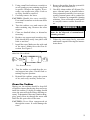
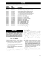
NOTE: Carefully notice the orientation of all
internal parts as they are removed, especially the orientation of the rotor to the
flow direction arrow. See Figure 2.
NOTE: Do not over tighten the flange bolts.
This may cause the gasket to be compressed into the flow stream and may
decrease the accuracy of the meter.
Figure 2
Support Rotor
Retaining Ring
4
Support
Retaining Ring