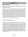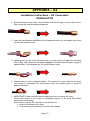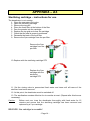
1
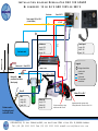
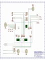
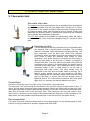
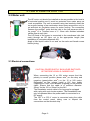
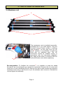
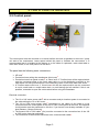
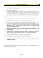
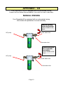
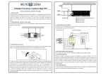
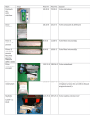
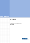
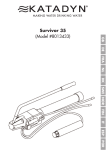
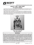
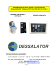
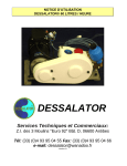
USER’S MANUAL DUO100® AC&DC installation and utilisation First bi powered water maker world-wide, producing 100 L/Hr, with automatic rinsing – model patented DESSALATOR Technical and Sales Departments : Z.I des 3 Moulins – « Euro 92 » – Bât. D – rue des Cistes – 06600 ANTIBES FRANCE Tel: (33) (0)4 93 95 04 55 Fax: (33) (0)4 93 95 04 66 e-mail: [email protected] Web site: www.dessalator.com Version A3 CONTENTS 1. Components page 1 2. How to install the desalinator: Sea water inlet page 2 Motor unit page 3 Membrane unit page 4 Control panel page 5 3. Starting the Dessalator® page 6 4. Directions for use (membranes) page 7 5. Maintenance: 5.1 Maintaining and 5.2 rinsing the membranes 5.2 Rinsing the membranes page 8 page 9 5.3 Sterilizing the membranes 5.4 High pressure pump page 10 page 10 6. Spare parts and accessories page 11 Appendix: A1: Reverse osmosis page 12 A2: How to assemble the HP connectors page 13 A3: Sterilizing cartridge – Instructions for use page 14 A4: Manual rinsing page 15 A5: Troubleshooting A5: Troubleshooting – Led indicator page 16 page 17 Connections plan: Connections DES 12/23/230V DUO- Doc : RAC_DUO – 4/12/10 Installation diagram Dessalator DUO 100 AC&DC Bi powered: 12 or 24 V AND 120V or 230 V Production Diam. 10 N°3 Power supply 120 V or 230 V (circuit breaker) N°1 HP 1 Water line Fresh water tank Control panel Length: 320 Width: 200 Depth: 150 N°2 Membranes Length: 700 Width: 270 Height: 120 Diam. 12 N°8 Motor 120 V or 230 V Rinsing with pressurized fresh water (Board pump) Control cable 3x1.5mm² Diam.12 N°4 Cable 3x1.5mm² Legend: Waste oulet 1 Rinsing solenoid valve control cable Sea water Fresh water HP hose pump membranes Diam.12 Motor 12 V or 24 V Filter Width: 310 Height: 390 Depth: 240 Strainers need to be looking forward on the hull of boat Motor unit Length: 710 Width: 400 Height: 240 Positive connection on relay with brown cable: 35 mm² Negative connection on motor with Green/yellow cable: 35 mm² en 12V et 24 V DESSALATOR, Z.I. des 3 Moulins-282, rue des Cistes- Bât. « Euro 92 » D, 06600 Antibes . Tél: (33) (0)4 93 95 04 55 Fax: (33) (0)4 93 95 04 66 e-mail: [email protected] 1. Components supplied with the Dessalator®: Version A3 Hull valve: It must be located the lowest possible in the boat, to the back for a motor yacht or in the centre near the keel for a sailing boat. The hull valve strainer filters out the larger particles at system entrance. Pre-filter: It must be located the nearest possible to the hull valve and be compulsory under the waterline. If not possible, there is a solution: to install a LP pump (optional). The pre-filter filters out solid particles down to 5 µm at the motor unit inlet. It is supplied with wrench. For automatic rinsing, an electro valve is mounted. Motor unit: It must be located compulsory under the waterline. The motor unit is comprised of the 12 or 24 V motor and the 120 or 230 V motor. It should be installed in a wellventilated space. BEWARE: In 120V, please think of an even more important ventilation of the motor unit than in 230V. Membrane unit: The membrane unit includes 3 membranes 2521 assembled in a compact frame. According to the model, a fuse or a circuit breaker is supplied. Control panel: includes a HP gauge, a flowmeter, an on/off switch, a pressure adjustment knob, an operating time meter, 3 indicator lights. Pipes and hoses supplied by Dessalator®: - High pressure pipes pump/membranes and membranes/control panel (2 pipes and 4 special connectors) Water production pipe membrane / control panel. Additional hardware needed for assembly: Miscellaneous screws (including Parker) Stainless jubilee clips 10mm and 12mm Assortment of plastic rings (tie wraps) Teflon tape or insulating water proof tape Silicon Rubson mastic, Sicaflex or equivalent Ribbed insulating pipe for cables and HP tubes Tricoflex hoses 10mm and 12mm Power cable: 35mm² for the 12V and 20mm² for the 24V Various tools (electric drill, saw, …) - Page 1 - 2. How to install the watermaker: 2.1 Sea water inlet Sea water inlet valve: The strainer should be positioned as low as possible below the waterline and as far as possible from the deck waste oulet. Drill the hull 21mm. The grooves on the strainer should be facing forward (towards the bow) for maximum water intake when the boat is moving forward. Please seal watertight with Rubson mastic or Sicaflex and ensure that the immersed part is painted with underwater grade paint. The hull valve should be accessible for maintenance. Make the valve / strainer and valve / hose connector watertight using 577 Loctite or Teflon tape. Cartridge pre-filter: The pre-filter should also be positioned as low as possible below the waterline and it should remain accessible. The mounting bracket is reversible, which facilitates the height positioning. The hose connection must be done with 12mm inner diameter Tricoflex for all the sea water circuit and the pressurized rinsing. Don’t forget to place two stainless steel collars on each connection. 5cm space should be left below the filter body to allow the filter basin to be removed. A wrench is supplied to dismantle the filter. The fresh water pressurized rinsing must be connected to the output of your board pump. An electro-valve is mounted on the output (diam. 12) for automatic rinsing. It can be connected under a sink, a wash basin or on the way of pressurized cold water hoses. The valve handle must be positioned to the front when the water maker is working. For a manual rinsing, please move the valve handle to the back. When replacing the filter cartridge, please check that the O-ring seal for the basin is secure and that the bleeder screw is tightened and fill the circuit without pressure with fresh water again for 3 to 4 minutes, put then the handle to the front. Connections: Hull valve / three-way valve, Pre-filter / pump, Fresh water / three-way valve The sea water inlet valve should be connected to the pre-filter using a tricoflex hose of inner 12mm, for sea water circuit and rinsing under pressure. Mount two jubilee clips at each joint, with their tightening heads positioned diametrically opposite on the hose. Connect the pressurized fresh water from the water oulet to the three-way valve. This connection can be made under a sink, wash basin or anywhere on the length of the pressurized fresh water pipe. When operating in sea water mode, the valve handle should be positioned in line with the filter (see photo above). Recommendation: If the pipe must pass through dividing walls or touch sharp edges, use an insulating pipe or tube superior to the pipe diameter to protect it against wear and friction. - Page 2 - 2. How to install the DUO 100: 2.2 Motor unit: The HP motor unit should be installed as low as possible in the boat in a horizontal position and it must be protected from water spray as much as possible. The unit is mounted using two brackets under the two motors leaving a few centimetres clear space around the unit, to get sufficient air circulation space for motor cooling. The connection 1 between the prefilter oulet and the inlet to the low pressure side of 2 the pump is in Tricoflex hose of 12mm with doubled stainless jubilee clips at each joint. The HP head of the pump is connected to the membrane inlet (red mark) through an HP pipe, cut to the appropriate length (see installation of connectors appendix A2). Apply a little liquid Loctite or nut seal on the male and female cones before joining. 1 2 2.3 Electrical connections: CAUTION: POWER SUPPLY SHOULD BE SWITCHED OFF BEFORE WORK IS CARRIED OUT. 4 Negative battery cable 3 Positive battery cable . Please connect a fuse holder to this cable. Neutral (blue) phase (brown) When connecting the 12 or 24V motor ensure that the 3 polarity is correct: positive (brown wire ) on the relay and 4 negative (green/yellow wire ) on the 12 or 24V motor. Depending on the voltage install a 12V fuse holder (supplied) or a 24V circuit breaker (supplied) on the positive cable. Ensure that the cable is of sufficient diameter: 35mm² for the 12V or 20mm² for the 24V. The Dessalator control cable is 5m long and is equipped with a plug with a pin locator system. The Dessalator® can only be operated when the power cable is connected to a DC supply. The 120 V or 230 V motor is connected using the cable from the control panel, taking care to respect the connections on the terminal strip. Ground (Yellow / green) - Page 3 - 2. How to install the desalinator: 2.4 Membrane unit 3 1 2 The membranes can be installed horizontally, preferably flat or on a wall support. They are mounted using 8 Parker screws in stainless 1 steel brackets . As the hose from the HP 2 pump vibrates, it is preferable to install the hose with an insulating tube. The HP connectors should be installed strictly in accordance with the instructions (Appendix A2). Apply a little loctite or nut seal to the two male and female cones before tightening. 3 Recommendation: To facilitate the connection , it is possible to rotate the heads through 90° by unscrewing the grey production connectors. Remove the nut covers and loosen the 12 nuts maintaining the unit. Remove the rod to obtain access and rotate the membrane head using a box wrench to join the stainless steel connector. Reinstall the rod and tighten the assembly. - Page 4 - 2. How to install the desalinator: 2.5 Control panel: 1 3 2 1 5 6 8 7 4 2 The control panel must be mounted on a vertical surface as close as possible to the motor / pump unit and to the membranes. Leave space behind the panel to facilitate the connections. It is recommended that it is installed at the bottom or on the sides of cupboards, under chart table or main cabin seats, on the front panel of a rear bunk… The panel has the following water connections: HP hose1 Production hose exiting the membranes (blue hose)2 Production hose from panel to tanks3: a 10mm inner Tricoflex hose will be required which must be connected either to the fresh water tanks or to the distribution manifold on the fresh water unit inlet provided there is no constricting valve on the fresh water tank outlet. A Tricoflex waste oulet inner 12mm hose4 will also be required which can be connected to a sink, wash basin or cockpit water drain, to avoid having the hull redrilled. If this is not possible, remember to open the outlet valves before using the Dessalator. Electrical connection: The 12 or 24V motor power cable5 with a connector and pin location system is connected to the cable exiting the 12 or 24V motor. The 120 or 230V motor power cable6 (mentioned on the cable) of 6m length is to be connected from the control panel to the 120 or 230V control panel of the boat. The supplied circuit-breaker must be positioned on this line, if you haven’t one already available on your boat (Beware: 6 Amps minimum). The second 120 or 230V cable7 (6m) must be connected to the connection box of the 120 or 230V motor (see plan enclosed). The connection of the solenoid valve has to be connected with cable8 . - Page 5 - 3. Starting the DUO: 1. Ensure the valves are open before starting up the watermaker (Hull valve and waste oulet valve if relevant) 2. To be done compulsory: For the first use, after the replacement of the filter, when lifting the boat out of the water or for a long period of not using your water maker, please fill the circuit with fresh water: put the handle valve on the pre filter to the back; this operation should be done for 3 or 4 minutes, water maker stopped and pressure captor open (fully anti-clockwise). Once the circuit is full of fresh water put the valve handle of the pre filter to the front. 3. It is important to take account of the ampere capacity of the batteries and of the working duration: for a use without any risk, it is better to start the motor of the boat. 4. To start the watermaker, the pressure regulator must be open. Switch on. 5. Turn the pressure regulator dial to the right until the HP gauge reading is in the orange zone then gradually adjust until the needle reaches the beginning of the green zone. Check that the pressure remains constant. The purpose of this operation is to remove air from the system and to obtain a more constant pressure while the watermaker is running. 6. Fresh water quality and flow into the tank is automatically monitored by the electronics board. 7. If pressure becomes too high the watermaker will cut out and the red indicator will light up. If this occurs, reduce pressure, switch off and restart the watermaker. 8. To shut down the watermaker: switch off then reduce pressure. 9. To shut down with rinsing, please see instructions page 8 and 9. 10. If the watermaker is not used for extended periods of time it should be rinsed preferably once a month. If not, the membranes will have to be sterilized for the storage (for 6 months). Note: Fresh water production depends on the temperature of the sea water and on the cleanness of the 5µm pre-filter. - Page 6 - 4. Directions for use: MEMBRANES DELICATE COMPONENTS Reverse osmosis membranes must be carefully maintained as they are the most delicate elements of the system. We recommend that the maintenance instructions are carefully followed to prevent the membranes from damage and to ensure the guarantee is not invalidated. Maximum production capacity of the desalinator is achieved with a sea water temperature of 25°C. The functioning of the membranes will vary depending on the temperature of the sea water. Output drops by approximately 2.5% to 5% for each degree below 25°C. Extreme temperatures: The membranes should not be exposed to temperatures below 0°C. Overpressure due to expansion caused by freezing can rupture the membranes and prevent the salt from being filtered out. The membranes must not be exposed to temperatures above 60°C as high temperatures may also prevent salt from being removed. Drying out of the membranes: The membranes should be permanently immersed in liquid either sea water before treatment, fresh water provisionally stored or sterilizing liquid if the desalinator is not used for extended periods of time (See sterilization methods appendix A3). Sterilizer is effective for six months and must be replaced after this period of time. Recommendations for use: The various quality and salinity grades of sea water affect both membrane efficiency and the working of the desalinator in Marinas. The system is not recommended for use in muddy or polluted water (briny water, river, Red Sea), which can clog the pre-filter and damage the membranes. However, if the desalinator has to be used in such conditions only run it for very short periods, as soon as clean sea water becomes available rinse the membrane and run the system without pressure for 30 minutes with the pressure regulator open. - Page 7 - 5. Maintenance: CAUTION: IN FREEZING CONDITIONS, PLEASE EMPTY THE FLOWMETER TUBE ON THE CONTROL PANEL BY DISCONNECTING THE PRODUCTION HOSE AND BLOWING OR INJECTING AIR INTO THE HOSE, PROTECT YOUR MEMBRANES WITH BLANKETS. 5.1. Maintaining the membrane After 1,000 working hours, it is normal that the flow lowers between 10 and 15%. If more, you should think of replacing the membranes. The volume of production of your watermaker can be made over the first 24 to 48 hours of operation. If the drinking water produced falls below the normal working specifications (sea water containing a TDS of 35,000 ppm, a sea water temperature of 25°C, and pressure of 65 bars), and if production is not improved by rinsing the membrane, then the membrane has to be replaced. Please take into consideration that the volume of drinking water produced is dependent on ideal sea water temperature and on pressure in the system. Therefore, if the volume of drinking water produced falls it does not necessarily mean that the membrane needs to be replaced. 5.2. Rinsing the membranes Once a week, the watermaker needs to be flushed with fresh water before using it to make fresh water. There is no need to flush it with fresh water after each use, as this is just a waste of water that is taken from the boat’s tank. There are 2 methods to flush the system: manual and automatic. Both systems are using the water that are in the tanks of the boat, and there is no use in water from the dock or a connection of any hose from a source outside the boat. Remember: The biggest enemy of the membranes is fresh water. Fresh water should be always used with no pressure when going through the system (pressure dial turned all the way anti clockwise) and the system should always run with no pressure after a fresh water flush to dump all the fresh water that are in it, before making freshwater from sea water (also with the pressure dial all the way anti clockwise). When running the watermaker with the dial all the way anti clockwise, it will shut it self down automatically after 1 minute. Only then, the watermaker is ready for use. - Page 8 - 5. Maintenance: Manual Flush Next to the pre filter there is a valve. The valve is connected to the fresh water system of the boat and turning it, will automatically start the boat’s water pump and a flow of fresh water from the tank to the watermaker. 1. Don’t turn the watermaker ON. Leave it on it’s OFF position. 2. Turn the pressure dial all the way anti clockwise. 3. Turn the valve of the fresh water intake, which is located next to the filter, for 2 minutes. The boat’s water pump will start and fresh water will run through the watermaker. Automatic Flush After using the watermaker, don’t switch it off. While the watermaker is still running, turn the pressure dial all the way anti clockwise. The watermaker will stop making water and will automatically start the flushing process. The green and orange lights on the control panel will turn on, which indicates that flushing is in process. This should take 30 seconds and will stop automatically. The green and orange lights will shut off and the only indicator will be the blue flashing light on the ON/OFF button, to remind you to shut the watermaker OFF. The automatic flush is a better way to flush the system since it’s not only flushes the sea water out, it also back wash the pre-filter and dumps all the dirt and debris that accumulated in the filter’s housing, back to the sea, through the sea water intake. DON’T FORGET!!! After each system flushing, before using the watermaker you need to: 1. Make sure the pressure dial is turned all the way anti clockwise. 2. Turn the watermaker ON and let it run with no pressure for 1 minute until the red alarm light comes on. This is the time needed for the sea water to replace all the fresh water that are in the system, before running pressurized sea water through the membranes. RUNNING FRESH WATER IN HIGH PRESSURE THROUGH THE MEMBRANES WILL DAMAGE THE MEMBRANES!!! - Page 9 - 5. Maintenance: 5.3. STERILIZING THE MEMBRANE When should the membrane be sterilized? Normally, regular monthly rinsing of the membrane may be all that is required to maintain the membrane. If this is not possible, sterilization will be necessary. A sterilisation procedure should be carried out every six months. Membrane sterilizing procedure: 1. Manual method: Thoroughly rinse the desalinator with fresh water for 10 minutes, using the three-way valve on the pre-filter. This procedure should be followed while the machine is idle. Pour the sterilizer (entire packet contents) into a bucket containing 8 litres of water. Disconnect the sea water inlet hose and immerse it in the bucket. Run the desalinator without increasing pressure until the bucket is empty. When the bucket is empty and the procedure is completed, the hose can be reconnected. If not, see number 3. 2. The sterilizing procedure can also be carried out using a garden spray: Pour the entire packet contents of sterilizer into a bucket containing 8 litres of fresh water and mix thoroughly. Fill the spray bottle with this mixture and spray the sterilizer into the watermaker inlet, at a spray pressure of 3 to 4 bars. If not, see number 3. 3. Sterilizing cartridge ST2: We have developed a sterilizing cartridge which makes this procedure very simple and easy. Cartridge instructions are given in appendix A3. Before using the desalinator again simply rinse with fresh water for a few minutes using the threeway valve on the pre-filter and all traces of the sterilizer will be removed. 5.4. HP Pump The HP pump is half filled with oil to the indicated level on the gauge. Normally no additional oil is needed throughout the life of the watermaker. However, if refilling is necessary, use multi grade oil 15W40 and do not exceed the indicated level (in the middle of the red mark on the gauge which is on the back of the pump to the opposite of the pump head). BEWARE: the sticker located on the red oil filling cap of the HP pump is there only for the shipment: it must be removed before use. - Page 10 - 6. SPARE PARTS AND ACCESSORIES Spare parts Dessalator® systems are very reliable, hardwaring and do not generally require expensive services. Nevertheless an accident is always possible (running without enough water, accidental overpressure, impact,…). Should the need arise, we supply spare parts and maintenance accessories: 5µm 10 ft filter driving belt motor relays production solenoid valve HP pump seals and valves HP hose (sold by meter) Connector for HP tube Flowmeter tube Accessories: Sterilizing cartridge ST2 Sterilizer bag Mineralizing cartridge - Page 11 - APPENDIX – A1 REVERSE OSMOSIS What is the reverse desalinating system? osmosis principle used in your Sea water is forced at high pressure through the membranes which act as “molecular sieves”, only allowing pure fresh water to pass through. Most dissolved solid particles will not penetrate the membrane. This waste, along with the remaining saline solution, will flow on the surface of the membranes and will be rejected. Not all particles dissolved in sea water can be eliminated. The system is designed to reject 99% of the TDS (Totally Dissolved Solids); approximately 2% of the 35,000 PPM/TDS will pass through the membrane. This guarantees drinking water with a TDS value of 500. Please note that the drinking water produced by your reverse osmosis system is essentially sterile, however, your fresh water storage should be treated periodically with chlorine or iodine and it should be also mineralized to ensure it remains consumable. Pay attention not to allow chlorine into the desalination system, as this could damage the device. How does your desalinator work? Sea water enters the inlet valve which penetrates the hull. This sea water is then routed through the 5 µm pre-filter. The filtered water is forced through the membrane by the HP pump (operating pressure 60 to 65 bars). The pressurised water passes through the surface holes of the membranes depositing the salt and minerals, which are then rejected into the sea with the remaining solution. The now fresh water flows over a detector which measures its salt content: If the desalination achieved is satisfactory, the three-way valve automatically directs the fresh water to the tank. If the salinity values measured by the salinity probe are too high (conductivity > 1,000 siemens), the valve will reject the water produced into the sea. The volume of drinking water being treated at any time is monitored by a flowmeter on the control panel. The production capacity of fresh water is achieved with a sea water temperature of 25°C. The output drops by approximately 2,5 to 5% for each degree below 25°C. - Page 12 - APPENDIX – A2 Installation instructions – HP Connectors DESSALATOR 1. Screw the brass union (skirt) anti-clockwise onto the HP pipe, no more than 2.5cm. Stop where the inner threading disappears. 2. Insert the steel tapered end-piece into the stainless steel nut, and tighten very firmly on the male tapered union. 3. Lightly grease the tip of the stainless steel cone and screw it straight into the brass union. Stop where the steel threading disappears into the brass end-piece (a gap of approximately 7mm between the nut and the brass union) 4. Unscrew the nut of the tapered adaptor. The connector is now ready for the hose from pump to membrane. We recommend using an insulating pipe to protect it against vibrations. 5. IMPORTANT: Check carefully that the end-piece does not block the hose: - Please don’t forget to put Loctite or watertight product on the male and female cones when remounting. - Please check that the HP connector is not blocked up. either by blowing into the hose or by inserting a screwdriver to check free passage. - Page 13 - APPENDIX – A3 Sterilizing cartridge – instructions for use The desalinator is not running: 1. Close the sea water inlet valve. 2. Open the sterilizing cartridge 3. Remove the top grid 4. Place the foam filter at the bottom of the filter 5. Pour the powder into the cartridge 6. Replace the top grid and close the cartridge 7. Check that the seal is properly positioned. 8. Dismantle the basin of the pre filter 9. Remove the 5μm cartridge from the pre-filter. Remove the 5μm cartridge from the pre-filter 10. Replace with the sterilizing cartridge ST2 Replace the 5μm cartridge with the sterilizing cartridge ST2 11. Set the rinsing valve to pressurized fresh water and rinse until all traces of the sterilizer have been removed. 12. At this point, the desalinator must be switched off 13. The sterilisation remains effective for six months at most. (Repeat after this time as necessary). Caution: Before next use, rinse the desalinator thoroughly with fresh water for 15 minutes and ensure that the sterilizing cartridge has been removed and replaced by a 5 μm cartridge. BEWARE: this cartridge is reusable! - Page 14 - APPENDIX – A4 Your DESSALATOR® is equipped with an automated rinsing. Please find her below the procedure if you wish to rinse it manually. MANUAL RINSING Your Dessalator® is equipped with an automated rinsing. Here below the procedure to rinse manually. Manual rinsing and sterilization: Valve handle to the back. HP pump Fresh water inlet Sea water inlet Normal position for a use with sea water: Valve handle to the front HP pump Fresh water inlet Sea water inlet - Page 15 - APPENDIX – A5 Troubleshooting PROBLEM Leak on the pressure regulator in front of the control panel Noisy HP pump. Oil leak on HP pump Insufficient water flow Water leak under the HP head CAUSE SOLUTIONS Loosened regulation cable gland Tighten the cable gland with a 12 wrench. - Reduced water inlet or air inlet in the system. - Leak on pump head seals. - Worn seals on connecting rods - Very cold water - Dirty pre filter - Tension drop on the power cable - Replace the seals. - Replace the pre filter Recharge batteries Check the connection. Inadequate power cable section, reinforce cable section. - - Replace plunger seals Worn seals No pressure reading Insufficient water Pressure doesn’t come Dirty pump valves up. - Page 16 - Ensure correct size of hoses (diameter), clips and filters secure and filters clean. - Replace seals. Open the hull valve and / or the rinsing valve Dismantle and clean the valves in the pump head APPENDIX – A5 Troubleshooting: led indicator - Page 17 -