1
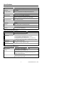
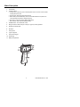
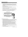
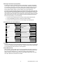
User’s Manual
InfraRed Thermometer with Laser Pointer
MODEL 42525A
Introduction
Congratulations on your purchase of Extech’s 42525A IR Thermometer. The Model
42525A provides non-contact (IR) and contact (type K) temperature measurement
capability. The built-in laser pointer (activated by pressing the meter’s trigger) increases
target accuracy. The Model 42525A has an RS-232 PC Interface jack for recording
readings as they are taken. Professional features include EMISSIVITY ADJUST,
RELATIVE MODE, DATA HOLD, DISPLAY OFFSET, and MIN MAX DISPLAY. Proper
use and care of this meter will provide years of reliable service.
Safety
1. Use extreme caution when the laser beam is ON
2. Do not point the beam toward anyone's eye
3. Be careful not to let the beam strike the eye from a reflective surface
4. Do not use the laser near explosive gases or in other potentially explosive areas
Warranty
EXTECH INSTRUMENTS CORPORATION warrants this instrument to be free of defects in parts and
workmanship for one year from date of shipment (a six month limited warranty applies to sensors and cables).
If it should become necessary to return the instrument for service during or beyond the warranty period,
contact the Customer Service Department at (781) 890-7440 ext. 210 for authorization or visit our website
www.extech.com for contact information. A Return Authorization (RA) number must be issued before any
product is returned to Extech. The sender is responsible for shipping charges, freight, insurance and proper
packaging to prevent damage in transit. This warranty does not apply to defects resulting from action of the
user such as misuse, improper wiring, operation outside of specification, improper maintenance or repair, or
unauthorized modification. Extech specifically disclaims any implied warranties or merchantability or fitness for
a specific purpose and will not be liable for any direct, indirect, incidental or consequential damages. Extech's
total liability is limited to repair or replacement of the product. The warranty set forth above is inclusive and no
other warranty, whether written or oral, is expressed or implied.
2
Model 42525A Version 4.0 5/05
Specifications
General Specifications
Display
0.4" (10mm) 5-digit LCD display
Sample rate
1 sec. approx.
Over range indication
Dashes are displayed when the reading exceeds specified limits
Laser pointer
Laser power < 1mW (red)
Max/Min Recording
Allows user to view only the MAX or MIN readings
Data output
RS-232c PC Interface for use with WindowsTM based communications
programs; Connection via 3.5mm phono jack on side of meter
Operating Temperature
32°F to 122°F (0°C to 50°C)
Operating Humidity
80% RH maximum
Power Supply
9V battery
Battery Life
Approx. 40 hours (20 hours with laser pointer ON)
Weight
0.6 lbs. / 265g
Dimensions
7.7 x 4.7 x 2.3” (195 x 120 x 58 mm)
Infrared Thermometer Specifications
Range / Resolution
-4 to 752oF (-20 to 400oC)
0.1oC/F
Accuracy
± 3% of reading or ± 6oF (3oC) whichever is greater
Accuracy notes
1.
2.
3.
4.
5.
Emissivity adjust
0.20 to 1.00 (factory default: 0.95)
Distance Factor
D/S = Approx. 6:1 ratio (D = distance, S = spot)
Wavelength
6 to 14 µm
Accuracy specified for readings between -10 and 350oC
Accuracy specified for ambient temperature (23oC ±5oC)
Accuracy specified for an emissivity of 0.95
Accuracy tested using 2.25” diameter black body at a distance of 6”
Testing environment: RF field strength < 3 V/M and frequency < 30MHz
Type K Thermocouple Specifications
Range / Resolution
-148.0 to 2372.0oF (-100.0 to 1300.0oC)
Accuracy
± (1% reading + 2oF); ± (1% reading + 1oC)
Accuracy note
Accuracy specified @ 23o ± 5oC
Thermocouple characteristics are not reflected in the Accuracy specs.
Linearity correction stored in CPU
Sensor type
Type K (NiCr – NiAl) Thermocouple (sold separately); Connects to
thermocouple jack on side of meter
3
0.1oC/F
Model 42525A Version 4.0 5/05
Meter Description
1.
LCD Display
2.
Function buttons
• C/F Button (also the UP button): Used to select temperature units. Also used as an UP arrow button
for setting the emissivity value
• Emissivity button: Enter the emissivity adjustment mode
• Relative button (also the DOWN button): Used to access the RELATIVE mode of operation. Also
used as the DOWN arrow button for setting the emissivity.
• Record button: Used when viewing the MAX and MIN readings
• Data Hold button: Used to freeze the displayed reading
3.
POWER button: Turns meter ON or OFF
4.
IR/Type K button: Selects IR (non-contact) or Type K (contact) operation
5.
RS-232 PC Interface jack
6.
IR Sensor
7.
Laser pointer
8.
Type K input jack
9.
Laser pointer trigger
10. Handle grip
11. Battery Compartment
4
Model 42525A Version 4.0 5/05
Operating Instructions
Infrared Measurement Procedure
1. Turn the meter ON by pressing the POWER button. The meter display will countdown
(99999, 88888, 77777…00000) during the self-test procedure. When the self-test is
complete, the display will indicate a temperature reading, the unit of measure, the
emissivity setting, and the measurement type (IR for non-contact or Type K for contact
measurements).
2. Use the IR / TYPE K button to set the display to the IR mode (IR will appear in the
lower left-hand side of the LCD).
3. Set the temperature units (oC or oF) using the C/F button.
4. Point the IR sensor toward the object under test (to assist with targeting, press the
meter trigger to activate the laser pointer).
5. This meter has a “distance to spot ratio” of 6:1. Use the diagram below to determine
the proper distance to hold the meter from an object. For example, if the object under
test has a diameter of 4”, hold the meter at a distance of approximately 26”.
6. Read the LCD display for the temperature measurement. Note that the current
emissivity setting is shown on the lower right-hand corner of the LCD.
Diameter of Spot
150
6
125
5
100
4
75
3
50
2
mm
inch
1000
40
840
33
670
26.4
500
20
330
13
mm
inch
Distance to Object
Infrared Measurement Considerations
1. The 42525A automatically compensates for ambient temperature deviations; however
it may take up to 30 minutes to adjust to extremely wide ambient temperature changes.
2. When low temperature measurements are taken followed by high temperature
measurements, several minutes are required for stabilization before the high
temperature measurements can be made accurately.
3. Measurement Field / Distance: For optimum accuracy, the object should be 1.5 to 2
times larger than the spot size shown in the diagram above and on the meter side.
4. Measurement Interference: Objects having low emissivity or objects with low
temperature yet high emissivity emit little IR energy. Such objects are adversely
affected by IR energy radiated from nearby objects having high emissivity and
temperature. For example, when such objects are measured in sunlight, erratic
readings occur because of the powerful radiation (sunlight) reflected off of the object's
surface into the 42525A sensor.
5. If the surface of the object under test is covered with frost, oil, grime, etc. clean before
taking measurements.
6. If an object's surface is highly reflective, apply masking tape or flat black paint
(emissivity 0.95) before measuring.
5
Model 42525A Version 4.0 5/05
Emissivity Considerations and Adjustment
The amount of IR energy emitted by an object is proportional to an object's temperature
and its ability to emit energy. This ability is known as emissivity. Emissivity is determined
by the material of the object and the object’s surface finish. Emissivity values range from
0.1 for a very reflective object to 1.00 for a flat black finish. The Model 42525A uses a
factory default emissivity setting of 0.95 (this setting covers most applications).
The closer the meter's emissivity setting is to the actual emissivity of the object under test,
the more accurate the temperature measurements will be. To calculate the emissivity of an
object: Measure an object's temperature using a Type K Thermocouple (use of a surfacemount thermocouple works best for this purpose) and note the reading. Measure the object
again using the IR sensor. Now, set the emissivity so that the IR measurement matches
the thermocouple reading. To set the emissivity:
1. Press and hold the Emissivity button until the emissivity display starts to flash.
2. Use the UP/DOWN arrow buttons to select the desired emissivity
3. Press and hold the Emissivity button until the display stops flashing to exit
Emissivity Factors for Common Materials
Material under test
Asphalt
Concrete
Cement
Sand
Soil
Water
Ice
Snow
Glass
Ceramic
Marble
Plaster
Mortar
Brick
Emissivity
0.90 to 0.98
0.94
0.96
0.90
0.92 to 0.96
0.92 to 0.96
0.96 to 0.98
0.83
0.90 to 0.95
0.90 to 0.94
0.94
0.80 to 0.90
0.89 to 0.91
0.93 to 0.96
Material under test
Cloth (black)
Skin (human)
Lather
Charcoal (powder)
Lacquer
Lacquer (matt)
Rubber (black)
Plastic
Timber
Paper
Chromium Oxides
Copper Oxides
Iron Oxides
Textiles
Emissivity
0.98
0.98
0.75 to 0.80
0.96
0.80 to 0.95
0.97
0.94
0.85 to 0.95
0.90
0.70 to 0.94
0.81
0.78
0.78 to 0.82
0.90
Data Hold
Press the HOLD button to freeze the displayed measurement. The “HOLD” icon will appear
on the LCD to indicate that the Data Hold mode is activated. Press the HOLD button again
to exit the Data Hold mode and return to normal operation.
Relative Measurements
While measuring, press the REL button to activate the Relative Mode (REL will appear on
the LCD in the upper right-hand corner). The measurement on the LCD at the time of the
button press will be displayed as 0.0o. Subsequent readings will be displayed as a
difference between the stored reading and the actual reading. Relative does not function
when either Data Hold or Data Record is enabled.
6
Model 42525A Version 4.0 5/05
Max/Min Recording
The Max/Min Recording feature offers the user to view only the highest (maximum MAX)
or the lowest (minimum MIN) reading. Press the REC button once to activate this feature
(the REC symbol will appear on the LCD). Press the REC button again to view only the
maximum reading (MAX). Press the REC button again to view only the minimum reading
(MIN). Press and hold the RECORD button again until the REC/MAX/MIN icons switch off
to return to normal operation.
Laser Pointer Operation
This 42525A is equipped with a laser pointer that is used to aim the
IR sensor more accurately. Simply press the meter trigger to activate
the laser pointer. Be extremely cautious when directing the laser
beam, shining the laser beam into someone's eye can cause serious
injury. Point the laser beam toward the device under test whose
temperature is to be measured.
Offset Adjustment
The OFFSET function allows the user to adjust the temperature readings in fine detail to
match an external calibrator, to compensate for display drift, or for other diagnostic uses.
Press and hold the HOLD and the REC buttons simultaneously. The small digits on the
lower right will match the temperature display of the larger digits when the two buttons are
held down correctly. While continuing to hold down the two keys, press the UP or DOWN
buttons to set the offset value on the larger digits. Release all keys to return to normal
operation.
Type K Thermocouple Measurement Procedure
1.
2.
3.
4.
5.
6.
Connect a Type K Thermocouple to the temperature input jack on the meter.
Power the meter by pressing the POWER button.
Use the IR / TYPE K button to select Type K mode (display will show ‘K’).
Set the temperature units (degrees C or F) using the C/F button.
Place the Thermocouple in the area where the temperature is to be measured.
Read the LCD display for the temperature measurement.
Type K Measurement Considerations
When a Type K Thermocouple is first connected to the meter and the thermocouple and
meter temperatures are different, several minutes should be allotted so that the
temperature of the socket matches the temperature of the thermocouple. The cold junction
compensation circuitry can then operate efficiently, allowing the meter to provide
measurements with optimum accuracy.
Auto Power Off
The meter will automatically power off after approximately 10 minutes in both IR and
Thermocouple measurement modes. To disable this feature, press the REC button.
RS-232 Serial PC Interface
This instrument includes a built-in RS-232 serial data port. This interface is intended for
use with the optional Data Acquisition Software and Cable . For more information, contact
Extech or refer to the manual with software package.
7
Model 42525A Version 4.0 5/05
Maintenance
Battery Replacement
When the low battery symbol
appears on the LCD, replace the meter’s 9V battery. The
battery compartment is located on the bottom of the meter's handle. Open the
compartment by sliding the battery compartment cover off. Replace battery and re-install
the battery compartment cover.
Cleaning
Wipe meter with a damp cloth when necessary. A mild detergent may be used but avoid
solvents, abrasives, and harsh cleansers. Do not allow moisture inside the meter.
Storage
Remove the battery if the meter is to be stored for long periods. Do not store the meter in
an environment that exceeds the published operating temperature and humidity
specifications.
Calibration and Repair Services
Extech offers complete repair and calibration services for most products we sell. For
periodic calibration, NIST certification or repair of most Extech products, call customer
service for details. Extech recommends that calibration be performed on an annual basis to
insure calibration integrity.
Support line (781) 890-7440
Technical support: Extension 200; E-mail: [email protected]
Repair & Returns: Extension 210; E-mail: [email protected]
Product specifications subject to change without notice
For the latest version of this User’s Guide, Software updates, and other
up-to-the-minute product information, visit our website: www.extech.com
Copyright © 2005 Extech Instruments Corporation
All rights reserved including the right of reproduction in whole or in part in any form
8
Model 42525A Version 4.0 5/05