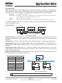
1
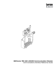
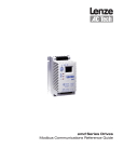
Application Note
Getting Started with CANopen for AC Tech Drives
Contained herein is the basic information for setting up AC Tech SMV Inverter and PositionServo drives for CANopen communication.
For detailed information on the CAN option module, refer to the product's CANopen Communication Reference Guide (PositionServo:
P94CAN01, SMV Inverter: CMVCAN01). Topics discussed in this application note include protocol, PDOs, SDOs, error control, network
management, termination, cable length, node addressing, EDS files plus master and drive configuration.
For Further Reference
CAN in Automation
http://www.can-cia.org
AC Tech Library
http://www.actech.com
Common Terms
CAN
Control Area Network
CANopen
Communication protocol to open and communicate with the Control Area Network
EDS
Electronic Data Sheet: an ASCII file containing a device’s communication functionality and objects;
plus its device-specific objects and their default values
EMCY
Emergency Object
Index
4-digit hexadecimal code used to identify an object: 16-bits
Sub-Index: decimal code to further identify object’s parameters: 8-bits
NMT
Network Management
OD
Object Dictionary
Object
Communication message - 4 types:
Administrative: NMT
Service Data Object: SDO
Process Data Object: PDO
Pre-Defined or Special Function Object: SYNC; TIME STAMP; EO
PDO
Process Data Object:
RPDO
Receive PDO
SDO
Service Data Object:
SYNC
Synchronization Special Function Object
TIME STAMP
Provides a common time reference, implemented as a CMS object
TPDO
Transmit PDO (also known as TxPDO)
Transferring Data
SDO: for large low priority data transfer between devices (i.e. configuring devices on CANopen network)
PDO: for fast data transfer of 8 bytes or less without protocol overhead (i.e. the data content has been previously defined)
Transmission Modes
Sychronous: synchronization by receipt of a SYNC message
Cyclic: transmission triggered periodically after every ‘n’ SYNC message
Acylic: transmission ‘pre-triggered’ by remote transmission request from another device
or by the occurrence of an object-specific event specified in the device profile
Asychronous: transmission is triggered by a remote transmission request from another device (by a CAN Frame)
Protocol
AC Tech CANopen equipped drives have CANopen slave functionality. In addition, both the SMVector frequency inverter and the Position
Servo drive support master messaging. Messaging is performed using cyclic & non-cyclic data transfer.
Note:
AC Tech/Lenze has its own dialect of CANopen (called SYSTEM BUS) that is used for master messaging between
drives. SYSTEM BUS messages can only be directed to/from supporting AC Tech/Lenze drives. All AC Tech/Lenze
CANopen products are compatible with CANopen (not SYSTEM BUS) protocol as slave devices.
Copyright © 2007 by AC Technology
AN 0022/A1
www.actech.com
For general information only. Content subject to change without notice.
May 2007
1-508-278-9100
Application Note
PDO
Parameter Data Objects (PDO) are the “cyclic” data mechanism on CANopen. There are 2 types of PDOs: transmit PDOs (TxPDO) and
receive PDOs (RxPDO). “Transmit” and “receive” refer to the PDO as seen by the CANopen slave device, so the data transmitted by the
CANopen master is actually the “RxPDO” for the slave.
PDOs offer efficient data transfer because a PDO contains only data. There is no mapping information included in a PDO. Each device
on the CANopen network must be pre-configured so that it knows how to handle each PDO. CANopen has several different methods of
determining when PDO data is to be transmitted as listed in Table 1. The transmission type is a CANopen object that is used to define the
scheduling of the PDO data. The SYNC message is broadcast by the master at a preconfigured time interval to synchronize the PDO data
transfers of the preconfigured slave devices.
Table 1: PDO Transmission
Transmission Type
TxPDO Transmission
Description
0
Synchronous, acyclic
Source data is read on SYNC; TxPDO only transmitted if data has changed
1 to 240
Synchronous, cyclic
Source data is read on SYNC; TxPDO transmitted every nth SYNC message
252
Synchronous, RTR
Source data is read when the SYNC message is received; TxPDO will only be transmitted when the RTR is received
253
Asynchronous, RTR
Source data is read and TxPDO is transmitted when the RTR message is received
254
Asynchronous
Source data is read and TxPDO is transmitted when:
255
Asynchronous
Event Timer
1: 0-to-1 transition in #MM.36
2: Event Timer
Non-Cyclic Data
There are several “Non-cyclic” data mechanisms on CANopen; the Boot up object, the Service Data Object (SDO) and Error control. The
Boot-up object is transmitted by the slave upon completion of its initialization sequence. Boot-up objects indicate to the master controller
that a new device is on-line and ready to receive communications.
An SDO is a “request-response” mechanism and only the CANopen master controller can initiate SDO messages. The request message
indicates if data is to be written or read, and contains “object” and “sub-index” mapping information to specify which object is to be
accessed, along with the data value (when writing). The slave device will issue a response message reflecting the status of the requested
command, object and sub-index. For a read message, the data value of the specified object will be returned.
Note:
A device must be an SDO client for it to act as a CANopen master controller and initiate SDO message over
the network.
Each SDO message allows 1 object to be read from or written to in the CANopen object dictionary. SDO
messages can handle up to 4 data bytes, allowing one 32-bit data value to be handled on each message.
Error Control is not a method of communication in itself, but there are communication routines that can run upon an error or run to detect
errors thereby making it a useful indicator of message transfer.
Node Guarding & Heartbeat
Two mechanisms are provided that guard against the loss of communications between the master controller and slave devices on the
CANopen network: Node Guarding and Heart Beat. In today's applications, the heartbeat method is used more frequently than the node
guarding method because its uses less bandwidth and is a more reliable, robust method.
Note:
The SMV supports both the guarding and heartbeat methods. However, a CANopen node can only or should
only use one method at a time. The PositionServo supports the heartbeat method.
There is also an Emergency Object that is transmitted once by a slave device to the master controller when a change in error state occurs
in the slave device. The Emergency Object contains several pieces of data from the slave to indicate the reason for the change of error
state. AC Tech products do not currently support the Emergency Object feature of CANopen.
Copyright © 2007 by AC Technology
AN 0022/A1
www.actech.com
For general information only. Content subject to change without notice.
May 2007
1-508-278-9100
Application Note
Network Management
Network Management (NMT) is used by the CANopen Master to control the operating status of all CANopen slave devices using the
Network Management commands and state machine. Support for this state machine is mandatory for all conformant CANopen devices. Certain objects are only active in certain modes. This allows devices to be configured before switching into operational state.
INITITALIZATION
only the BOOT UP object is active in this state
PRE-OPERATIONAL
NMT and SDO are active to allow device configuration and state control. SYNC is active, although it will have no effect as PDO is not
yet active. EMERGENCY is also active and will be transmitted if an error occurs.
OPERATIONAL
PDO becomes active to allow cyclic data transfer.
STOPPED
unable to communicate with object dictionary in this state, only NMT is active to allow device to be switched to another state.
For information about CANopen protocol as well as complete network planning and installation guides refer to the 'CAN in Automation'
website at: http://www.can-cia.org.
The Physical Network
PLC/PC
CANopen Master
GND
LO
HI
PositionServo
CANopen Slave
PositionServo
CANopen Slave
GND
LO
HI
CAN Network
HI
GND
LO
CAN Network
120Ω
120Ω
Figure 1: CANopen Network
Recommended cable: Various cables are offered by manufacturers for CANopen communication according to the type of environment/
application that the cable will be used in. One example from Belden is the Belden 9842. Check with your cable manufacturer for applications
compatibility.
Termination: CANopen networks are terminated at either end of the network with a 120 Ohm 1% ¼ Watt resistor as shown in Figure 1.
Network topology: CANopen uses a linear topology. CANopen nodes can be daisy-chained together or run from drop lines or any
combination of these methods. CANopen masters do not need to be located at any particular point. They can be installed anywhere on
the network.
Maximum number of nodes: CANopen allows up to 127 nodes to be connected to a single network, however, this is under specific
network loading and messaging conditions. For practicality, limit usage to 64 nodes per network. These can be a mix of slaves and
masters (also referred to as scanners).
Maximum network length and baud rate: The maximum length of cable in a CANopen network is dependent upon the baud rate used.
The faster the baud rate, the shorter the cable. Refer to Table 2.
Table 2: Baud Rate and Maximum Cable Length
20kbps
2500m
50kbps
1000m
125kbps
500m
250kbps
250m
500kbps
100m
800kbps
50m
1000kbps
25m
CAN
Module
CAN Network
CANopen
CANopen
CAN
Module
PositionServo Drive
CAN
Module
PositionServo Drive
I/O
. . . to 64 nodes
I/O
Motor
Feedback
Sensor
CANopen
Node 1
Sensor
Motor
Feedback
5000m
Status
Maximum Cable Length
10kbps
Control
Baud Rate
Master Controller
Node 2
Figure 2: Nodes on a Network
Note: Each device on the CANopen network must be set to the same baud rate.
Copyright © 2007 by AC Technology
AN 0022/A1
www.actech.com
For general information only. Content subject to change without notice.
May 2007
1-508-278-9100
Application Note
Basic wiring: AC Tech CANopen connectors utilize three leads: CAN+, CAN- and CAN GND. TxA is the same as CAN+ (High Terminal) and
TxB is the same as CAN- (Low Terminal). Table 3 shows the CANopen module pinouts for the SMVector and PositionServo drives.
Table 3: CANopen Module Pinouts
SMV
PositionServo
Terminal
Name
Description
Note
Terminal
Name
Description
Note
1
CAN_GND
Ground
Connect CAN_GND to the CAN Network
Common Ground.
If only 2 wires (CAN_L & CAN_H) are used
in the network, connect CAN_GND to chassis/earth ground.
1
ICOM
Isolated
Common
Connect ICOM to the CAN Network Common
Ground.
2
TxB
Transmit B
3
TxA
Transmit A
If controller is located at either end of the
network, a terminating resistor (120W typical)
should be connected across TxB and TxA.
2
CAN_L
Low
3
N/A
Not used
4
CAN_H
High
5
N/A
Not used
If controller is located at either end of the
network, a terminating resistor (120W typical) should be connected across CAN_L and
CAN_H.
Node addressing: Valid CANopen addresses are between 1-127. Each node must be addressed to a unique number. Set the node address
and baud rate of the drive locally (via the keypad). There can be restrictions placed upon the node ID when using up a second parameter
channel, i.e. when SDO#2 is enabled in the SMVector the node ID must be set between 1-63 as 64-127 are used for SDO2. Refer to the
user manual for your device. By default most CANopen devices will power up at address 1. It is important to try to leave this address
available on the network so that replacement of a node does not cause a conflict.
The EDS File
The EDS (Electronic Data Sheet) file is basically a lookup table. It tells the CANopen master what the slave is and how its memory is
mapped. The EDS file needs to be read into the CANopen master. This is done via configuration software and is particular to the CANopen
master being utilized. AC Tech drives communicating via SYSTEM BUS do not need to have an EDS file read in (nor can they read in an
EDS file) to act as a master for messaging to other system bus drives. One example of this is a PositionServo drive writing a network
variable to another PositionServo drive.
Configuration
CANOpen master configuration: There are various utilities to configure CANopen master devices. The utility will be particular to the
master in use. Check the user’s manual of the specific device you are using. Ultimately that software will have a way to register the EDS
file for the slaves. The EDS file needs to be registered and the messaging connections must also be set up. The AC Tech drive is controlled
by PDO messaging. PDOs can contain up to 64 BITs of data. Mapping is a pointer that indicates the BITs assigned to each parameter or
drive function.
Drive configuration: You will need to select the CANopen mapping. Simply put, the drive can package varying configurations of data
for the PDO messages. Refer to the user manual of your product to select the assembly containing the data you need for your particular
application. For the drive to take start/stop commands from the CANopen master, set the drive’s control source to NETWORK CONTROL. To
allow the drive to take speed reference commands from the CANopen master, set the drive’s speed reference to NETWORK REFERENCE.
WARNING!
Never reset a faulted drive locally! Always reset via the CANopen master. Failure to do so may
result in unexpected operation.
WARNING!
Always send a low rotation speed command to a drive prior to changing direction. If both the
direction and the speed setpoint are programmed to change at the same time, the drive may for
a short time change direction and run at the wrong speed.
Copyright © 2007 by AC Technology
AN 0022/A1
www.actech.com
For general information only. Content subject to change without notice.
May 2007
1-508-278-9100