1
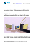
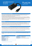
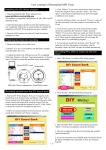
Website: www.luxielectronics.com
Email: [email protected]
Phone: +1 (949) 654-2047
Address: Irvine, CA, USA
For terminating HDMI regular wires
Thank you for purchasing the Luxi Electronics patented HD DIY (Do It Yourself) field termination products.
If you are an experienced installer with the DIY products, you can just print out this first page with wire
color coding picture for your reference. If you are new to the DIY products, please make sure you read
through all the pages before performing the termination.
Wire color coding
Since there’s no industry-wide HDMI color coding standard, please follow the instructions below closely.
Making a new cable:
If you are using Luxi HDMI regular wires (or other branded HDMI regular wires with the same wire colors),
please follow the wire color coding below.
If you are using a HDMI regular wires with different wire colors, please mark the color cross reference on
a piece of paper and make sure the same wire goes to the same pin on both ends.
Repairing one end of an existing cable:
If you are repairing a pre-terminated HDMI cable and only need to re-terminate one end, please write
down the color coding for each pin carefully before cutting off the old plug.
HD DIY user manual regular wires
Revision: 2.00
Date: 1/26/2015
US patents: 8002572, 8500489 issued; additional patents issued or pending in multiple countries
Website: www.luxielectronics.com
Email: [email protected]
Phone: +1 (949) 654-2047
Address: Irvine, CA, USA
Identifying the components
First, make sure you have all the necessary parts for the field termination.
As shown in the picture above, you need the Luxi HDMI DIY connector components (5-piece), Luxi
connector clamshell (2-piece), Luxi HDMI regular wires (or other brand), Luxi hand tool and a knife.
Be familiar with the component names as show below. HDMI connector has a wider side with 10 pins
and a narrower side with 9 pins. We call the wider side the top side. The bottom wire holder can be
easily identified by a keyed slot off the rest of the slots, see the red circle in the picture. The newer top
wire holders are black, while the bottom wire holders remain white for easy identifications. For the two
wire holders, the side with many slots is the inner side; this is the side which will be pushed onto the
sharp pins of the connector core.
HD DIY user manual regular wires
Revision: 2.00
Date: 1/26/2015
US patents: 8002572, 8500489 issued; additional patents issued or pending in multiple countries
Website: www.luxielectronics.com
Email: [email protected]
Phone: +1 (949) 654-2047
Address: Irvine, CA, USA
Step 1, wire preparations
1.1 Use a blade to cut around a circle of the
HDMI cable overall jacket about 4 cm (1-1/2”)
from the end
1.4 Remove the overall aluminum foil; now the
19 wires inside the HDMI cable are exposed
1.2 Use the blade to slice along the cable
overall jacket then peel off the overall jacket
1.5 There are 4 twisted pairs. Cut off the plastic
wrap on each pair ¼” (6 mm) from the end
1.3 Fold back the braids
1.6 Cut off the aluminum foil from the very end
HD DIY user manual regular wires
Revision: 2.00
Date: 1/26/2015
US patents: 8002572, 8500489 issued; additional patents issued or pending in multiple countries
Website: www.luxielectronics.com
Email: [email protected]
1.7 Important! Twist each drain wire tightly into
a solid wire
Phone: +1 (949) 654-2047
Address: Irvine, CA, USA
Step 2, wire threading
2.1 Carefully thread the wire one by one thru the
wire holder per the color coding on page 1;
the entrance has counter-sink holes; thread
the 4 drain wires the last, make sure no
strands left out
1.8 Fan the wires out into two group base on
color coding on page 1
2.2 Important! Slide the wire holders as far
inward as they can go for best performance
Important tip: the most common potential
problem in DIY termination is the drain wire
short circuit to the adjacent wire, see the picture
below. If the drain wire is not twisted tightly,
some strands may fall out of the V shaped pin
and touch the next wire at point A. If the end of
the drain wire is not cut cleanly, it may touch the
next wire at point B. Pay extra attention to them
HD DIY user manual regular wires
Revision: 2.00
Date: 1/26/2015
US patents: 8002572, 8500489 issued; additional patents issued or pending in multiple countries
Website: www.luxielectronics.com
Email: [email protected]
2.3 Insert one of the wire holders all the way into
No. 1 hole of the hand tool following the
marked orientation; perform a pre-crimp.
Inspect the wire ends for any potential short
Phone: +1 (949) 654-2047
Address: Irvine, CA, USA
2.6 Check the finished wire holders
During the pre-crimp the recessed blade would
cuts off the wires and a tiny slice of the wire
holder; this is normal.
2.4 Slide and line up the other wire holder to
about the same position; repeat the precrimp to it. Inspect the wire ends for any
potential short
Check the cut wire ends for any potential short;
check the drain wires from 4 twisted pairs to
make sure they don’t touch each other, and
don’t touch the overall cable shield or won’t
touch the metal shells in the next step. Use
small piece of electric tape to cover it if
necessary. The touched drain wires may trigger
false reading of the tester (some LEDs might not
lit) but won’t affect overall signal performance.
Step 3, final assembling
3.1 Line up the two wire holders onto the
connector core; make sure the top holder
goes on top; inner side engage with the pins
2.5 This tool has a ratchet design. If you ever
need to release the latch, turn the thumb nail
in the marked direction
HD DIY user manual regular wires
Revision: 2.00
Date: 1/26/2015
US patents: 8002572, 8500489 issued; additional patents issued or pending in multiple countries
Website: www.luxielectronics.com
Email: [email protected]
3.2 Use your fingers to press the wire holders
into the connector core half way
Phone: +1 (949) 654-2047
Address: Irvine, CA, USA
3.5 Place the bottom metal shell onto the top
metal shell, line up the 4 notches, push
together until you hear or feel clicks
3.3 Insert the connector core with both wire
holders all the way into No. 2 hole of the
hand tool and perform crimp
3.6 Use the finger tips to gently bend the strain
relief tabs inward; be careful not to be cut
3.4 Slide the connector core into the top metal
shell, push up with your thumbnail until you
hear or feel a click
3.7 Use the hand tool’s No. 3 dies to crimp the
strain relief tabs onto the cable jacket with
regular wires; make sure it’s a tight crimp
HD DIY user manual regular wires
Revision: 2.00
Date: 1/26/2015
US patents: 8002572, 8500489 issued; additional patents issued or pending in multiple countries
Website: www.luxielectronics.com
Email: [email protected]
Phone: +1 (949) 654-2047
Address: Irvine, CA, USA
3.8 Trim off the excessive drain wires and braids
3.10
Place the top clamshell onto the bottom
clamshell and press them together until you
hear or feel clicks
3.9 Place the metal shells into the bottom
clamshell
3.11
Peel of the plastic protection skin from
the clamshells
Congratulations! You’ve just made a
beautiful HDMI termination!
HD DIY user manual regular wires
Revision: 2.00
Date: 1/26/2015
US patents: 8002572, 8500489 issued; additional patents issued or pending in multiple countries
Website: www.luxielectronics.com
Email: [email protected]
Phone: +1 (949) 654-2047
Address: Irvine, CA, USA
Testing
After finishing termination on both ends of the HDMI
cable, use a Luxi HHT-200 HDMI hand held tester to test
the cable and to make sure all pins are connected
correctly.
If some pins get crossed or shorted, cut off the end with
problem and re-terminate it.
Once pass the continuity test, connect the cable in the
system to perform a signal test. If you see a normal
picture on the screen and hear normal sound, the cable
is good.
Max cable length
The max cable length depends on many factors such as the signal data rate (resolution), source device
signal quality, TV sensitivity and the compatibility between them. As a rule of thumb, this DIY cable
typically should work for up to 12 m (40’) at 1080p signal rate. If the cable run is longer than 12 m (40’) or
you do not get a picture after the continuity test, insert a Luxi EHD-111 HDMI Extender at the TV end in
between the cable and the TV to extend the distance. The max distance with extender is up to 24 m (80’)
with 1080p signal.
Troubleshooting
The Luxi DIY components are well designed and made. As long as the wires are inserted into the correct
holes per the color coding on page 1, and drain wires are properly inserted to prevent sliding to the
adjacent holes to create a potential short, and the wire slacks are reduced to minimum by sliding the wire
holders as far as you can, the performance should be guaranteed by the design and better than the
equivalent factory soldered HDMI cables.
If the terminated wires passed the HDMI tester test, all the connections in the system are secure and the
all devices are powered up, but there’s no picture or sound on the TV, try the simple steps below for
troubleshooting:
1) Lower the source device (Blu-ray player, cable STB etc.) resolution to one step lower, e.g. from
1080p to 1080i; if the picture or sound comes out on the TV, then most likely the problem you had
before was bandwidth/cable length related. Insert the Luxi HDMI Extender between the cable
and the TV to fix the problem.
HD DIY user manual regular wires
Revision: 2.00
Date: 1/26/2015
US patents: 8002572, 8500489 issued; additional patents issued or pending in multiple countries
Website: www.luxielectronics.com
Email: [email protected]
Phone: +1 (949) 654-2047
Address: Irvine, CA, USA
2) If after lowering the source device resolution and there’s still no picture or sound on TV, then
most likely the problem in the system is caused by the DDC line communication error (also known
as handshaking or copyright errors). Insert a Luxi Communicator in between the cable and TV to
fix the problem.
See the HDMI troubleshooting guide on Luxi website for more details.
Technical support
Please contact your distributor or directly to Luxi Electronics for technical support.
Re-order part numbers
You can re-order these parts from authorized Luxi distributors:
Part number
22-001-02
22-001-03
22-002-06
22-002-07
68-009-11
68-010-01
68-011-01
74-035-01
74-006-01
75-002-01
Model
HD-28RD250
HD-28RD500
HD-30RB250
HD-30RB500
DIY-28DS10B
DIY-30BS10
DIY-28T
EHD-111
CHD-110
HHT-200
Description
HDMI 28 AWG raw regular wire, 76 m/250'
HDMI 28 AWG raw regular wire, 152 m/500'
HDMI 30 AWG raw ribbon wire, 76 m/250'
HDMI 30 AWG raw ribbon wire, 152 m/500'
10 pack HDMI 28 AWG DIY connector for regular wire and clamshell bundle
10 pack HDMI 30 AWG DIY connector for ribbon wire and clamshell bundle
HDMI 28/30 AWG DIY hand tool
HDMI Extender, F-M pigtail, T-grip slim plug
HDMI Communicator, F-M pigtail, optional 5 V power supply not included
HDMI hand held tester with open and short test, one 9 V battery not included
HD DIY user manual regular wires
Revision: 2.00
Date: 1/26/2015
US patents: 8002572, 8500489 issued; additional patents issued or pending in multiple countries