1
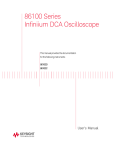
Operation and Maintenance Manual GASMAX CX Single / Dual Channel Gas Monitor GDS Corp. 1245 Butler Road League City, TX 77573 409-927-2980 409-927-4180 (Fax) ww.gdscorp.com GASMAX CX Operation & Maintenance Manual, Revision 1.0 CAUTION: FOR SAFETY REASONS THIS EQUIPMENT MUST BE OPERATED AND SERVICED BY QUALIFIED PERSONNEL ONLY. READ AND UNDERSTAND INSTRUCTION MANUAL COMPLETELY BEFORE OPERATING OR SERVICING. ATTENTION: POUR DES RAISONS DE SÉCURITÉ, CET ÉQUIPEMENT DOIT ÊTRE UTILISÉ, ENTRETENU ET RÉPARÉ UNIQUEMENT PAR UN PERSONNEL QUALIFIÉ. ÉTUDIER LE MANUE D’INSTRUCTIONS EN D’UTILISER, D’ENTRETENIR OU DE RÉPARER L’ÉQUIPEMENT. REVISION HISTORY Revision 1.0 4/15/14 Initial Release Copyright © 2014 GDS Corp. All Rights Reserved P/N 1200-0872-01 Page 2 ENTIER AVANT GASMAX CX Operation & Maintenance Manual, Revision 1.0 CONTENTS 1 SAFETY INFORMATION _______________________________________________ 7 2 OVERVIEW _________________________________________________________ 8 3 HARDWARE ________________________________________________________ 9 4 INSTALLATION _____________________________________________________ 10 Selecting a Location __________________________________________________________ 10 Explosion Proof Installation ___________________________________________________ 10 Intrinsically Safe Installation ___________________________________________________ 10 Mounting the GASMAX CX Instrument Enclosure __________________________________ 10 Connecting DC Power & Output Signal Wiring ____________________________________ 11 Connecting to an Ethernet Network _____________________________________________ 12 Optional Relay / MODBUS Interface ____________________________________________ 12 Optional MODBUS Junction Box ________________________________________________ 13 Local Smart Toxic sensor ______________________________________________________ 15 Connecting a Remote Toxic Sensor transmitter ___________________________________ 16 Local Smart Bridge Sensor _____________________________________________________ 17 Connecting a Remote INFRARED Sensor transmitter _______________________________ 18 Local GDS‐IR Infrared Sensor __________________________________________________ 19 Connecting a Remote GDS‐IR Infrared Sensor _____________________________________ 20 Connecting an External 4‐20mA Input Device _____________________________________ 21 5 SETUP AND OPERATION _____________________________________________ 22 GASMAX Controls and DIsplay _________________________________________________ 22 Display Screens _____________________________________________________________ 23 Initial Setup ________________________________________________________________ 24 Page 3 GASMAX CX Operation & Maintenance Manual, Revision 1.0 Normal Operating Mode ______________________________________________________ 24 Alarm Operation – ALARM 1, 2 and 3 ___________________________________________ 24 Alarm Operation – FAULT _____________________________________________________ 25 6 CALIBRATION ______________________________________________________ 26 Calibration Overview _________________________________________________________ 26 Calibration Procedure ________________________________________________________ 27 7 MAINTENANCE _____________________________________________________ 29 Normal Maintenance ________________________________________________________ 29 Sensor Replacement – Local Sensors ____________________________________________ 29 Sensor Replacement – Remote Sensors __________________________________________ 30 8 TROUBLESHOOTING_________________________________________________ 32 Toxic Sensor Indicates Fault or Overrange ________________________________________ 32 Toxic Sensor Will Not Calibrate ________________________________________________ 32 Bridge Sensor Indicates Fault or Overrange _______________________________________ 32 Bridge Sensor Will Not Calibrate _______________________________________________ 32 Receiving Device and GASMAX Displayed Values Don’t Match _______________________ 33 Controller MODBUS Data Incorrect _____________________________________________ 33 Controller Showing MODBUS COMM ERROR _____________________________________ 33 GASMAX Display Blank _______________________________________________________ 33 Software reset (“Cold Boot”) __________________________________________________ 33 9 SPECIFICATIONS ____________________________________________________ 34 10 USER MENUS ____________________________________________________ 35 Alarm Outputs Menu ________________________________________________________ 36 Channel Settings Menu _______________________________________________________ 37 Page 4 GASMAX CX Operation & Maintenance Manual, Revision 1.0 Comm Settings Menu ________________________________________________________ 39 System Settings Menu ________________________________________________________ 40 Diagnostics Menu ___________________________________________________________ 41 11 NETWORK INTERFACE _____________________________________________ 42 MODBUS Registers __________________________________________________________ 42 12 SPARE PARTS ____________________________________________________ 50 Sensor Head Accessories ______________________________________________________ 51 13 DRAWINGS AND DIMENSIONS ______________________________________ 52 Page 5 GASMAX CX Operation & Maintenance Manual, Revision 1.0 TABLE OF FIGURES FIGURE 3‐1 GASMAX CX GAS MONITOR ......................................................................................................... 9 FIGURE 4‐1: GASMAX CX I/O POWER & SIGNAL WIRING ............................................................................. 11 FIGURE 4‐2 ETHERNET INTERFACE ............................................................................................................... 12 FIGURE 4‐3 GASMAX CX OPTIONAL RELAY / MODBUS INTERFACE .............................................................. 12 FIGURE 4‐4: MODBUS WIRING JUNCTION BOX ............................................................................................ 13 FIGURE 4‐5: MODBUS JBOX LOCATION OPTIONS ........................................................................................ 14 FIGURE 4‐6: LOCAL SMART TOXIC SENSOR CONNECTION ........................................................................... 15 FIGURE 4‐7: REMOTE TOXIC SENSOR TRANSMITTER CONNECTION ............................................................ 16 FIGURE 4‐8: LOCAL SMART BRIDGE SENSOR CONNECTION ......................................................................... 17 FIGURE 4‐9 REMOTE INFRARED SENSOR TRANSMITTER .............................................................................. 18 FIGURE 4‐10: LOCAL GDS‐IR INFRARED SENSOR .......................................................................................... 19 FIGURE 4‐11: REMOTE GDS‐IR CONNECTION ............................................................................................... 20 FIGURE 4‐12: REMOTE 4‐20MA INPUT ......................................................................................................... 21 FIGURE 5‐1: GASMAX CX DISPLAY SCREEN SEQUENCE ................................................................................ 22 FIGURE 5‐2 GASMAX DATA DISPLAY ............................................................................................................ 23 FIGURE 5‐3 GASMAX TREND DISPLAY .......................................................................................................... 23 FIGURE 6‐1: CALIBRATION FLOWCHART ...................................................................................................... 28 FIGURE 7‐1: GASMAX SENSOR REPLACEMENT ............................................................................................. 30 FIGURE 10‐1: MAIN MENU TREE .................................................................................................................. 35 FIGURE 10‐2: ALARM OUTPUTS MENU TREE ............................................................................................... 36 FIGURE 10‐3: CHANNEL SETTINGS MENU TREE (1) ...................................................................................... 37 FIGURE 10‐4: CHANNEL SETTINGS MENU TREE (2) ...................................................................................... 38 FIGURE 10‐5: COMM SETTINGS MENU ........................................................................................................ 39 FIGURE 10‐6: SYSTEM SETTINGS MENU TREE .............................................................................................. 40 FIGURE 10‐7: DIAGNOSTICS MENU TREE ..................................................................................................... 41 FIGURE 12‐1: GASMAX CX + LOCAL SENSOR SPARE PARTS .......................................................................... 50 FIGURE 12‐2: GASMAX SENSOR HEAD ......................................................................................................... 51 FIGURE 12‐4: GASMAX SENSOR HEAD SPLASH GUARD & FLOW CELL ......................................................... 51 FIGURE 13‐1 GASMAX CX DIMENSIONS ....................................................................................................... 52 FIGURE 13‐2 GASMAX CX REMOTE SENSOR TRANSMITTER DIMENSIONS ................................................... 53 Page 6 GASMAX CX Operation & Maintenance Manual, Revision 1.0 1 SAFETY INFORMATION Important – Read Before Installation Users should have a detailed understanding of GASMAX CX operating and maintenance instructions. Use the GASMAX CX only as specified in this manual or detection of gases and the resulting protection provided may be impaired. Read the following WARNINGS prior to use. WARNINGS The GASMAX CX gas monitor described in this manual must be installed, operated and maintained in accordance with information contained herein. Installation in any hazardous area must comply with all applicable restrictions, requirements and guidelines for said hazardous areas. It is the end user customer’s final decision to ensure that the GASMAX CX is suitable for the intended use. The GASMAX CX is designed and constructed to measure the level of certain gases in ambient air. Accuracy in atmospheres containing steam or inert gases cannot be guaranteed. Always mount the sensor head vertically with the sensor head facing down. However, the GDS‐IR infrared sensor may be mounted vertically or horizontally. Do not paint transmitter or sensor assembly. Do not operate the GASMAX CX if its enclosure is damaged or cracked or has missing components. Make sure the cover, internal PCB’s and field wiring are securely in place before applying power. Do not expose the GASMAX CX to electrical shock or continuous severe mechanical shock. Protect the GASMAX CX and related sensor assemblies from dripping liquids and high power sprays. Calibrate with known target gas at start‐up and check on a regular schedule, at least every 90 days. More frequent inspections are encouraged to spot problems such as dirt, oil, paint, grease or other foreign materials on the sensor head. Periodically test for correct operation of the system’s alarm events by exposing the monitor to a targeted gas concentration above the High Alarm set point. Use only for applications described within this manual. Page 7 GASMAX CX Operation & Maintenance Manual, Revision 1.0 2 OVERVIEW The GASMAX CX is a single or dual channel fixed‐point gas monitor designed to provide continuous monitoring of toxic or combustible gases in hazardous areas. Gas values are displayed in calibrated engineering units as well as bar graph or 30‐minute trend graph format. The GASMAX CX supports one or two local or remote mount sensors for toxic or combustible gases. The advanced microcontroller, non‐intrusive magnetic interface and superior full color graphic LCD interface offers rapid setup, simplified operation and enhanced diagnostics not found in previous generation products. On‐board non‐volatile memory retains all configuration data during power interruptions. Two independent 4‐20 mA outputs allow for easy connection to control systems or other alarm instrumentation, and a built‐in Ethernet port allows the GASMAX CX to be easily integrated into a facilities network. Additional output options include 4x alarm relays and dual channel MODBUS slave interfaces. Built‐in user‐prompted calibration makes it easy for one person to perform calibration and maintenance without opening the enclosure or declassifying the area. A battery‐powered real‐time clock and event log allows the GASMAX CX to track calibration and alarm events for later recall on the LCD readout. For toxic gases the GASMAX CX supports a wide range of electrochemical (“echem”) sensors. These sensors use chemical reactions to sense the presence of gases such as hydrogen sulfide, chlorine, sulfur dioxide and many others. Unlike previous generation gas detectors, GASMAX CX sensors contain all the necessary micro‐electronics needed to convert the extremely low level sensor output signals into digital values that are immune to interference and noise. When combined with state‐of‐the‐art digital signal processing and filtering, the GASMAX is capable of gas detecting levels lower than ever before. For combustible gases the GASMAX CX offers three different choices. In addition to traditional catalytic bead (“cat bead”) sensor, the GASMAX CX supports the GDS Corp SmartIR infrared sensor and GDS‐IR infrared sensor as well as the latest generation photoionization detector (PID) sensors for measurement of volatile organic compounds such as benzene or toluene. Page 8 GASMAX CX Operation & Maintenance Manual, Revision 1.0 3 HARDWARE The GASMAX CX is enclosed in a CSA / FM / IECEx certified anodized aluminum explosion proof yellow enclosure designed to protect the electronics and make it easy for workers to identify in industrial environments. The screw‐on front cover is easily removed for installation and maintenance; however, built‐in user interface magnetic switches allow operators and technicians to adjust, calibrate or troubleshoot the GASMAX CX without declassifying the area. Local sensors are contained in a stainless steel sensor head, typically attached to the bottom of the GASMAX CX as shown below. The normal sensor head includes an integrated stainless steel flame arrestor that must be removed for the detection of certain reactive gases such as chlorine or chlorine dioxide. If removed, the GASMAX CX is not certified for use in hazardous areas. See Chapter 13 for drawings and dimensions. ¾” NPT Conduit Entry (2x) Color LCD Display Removable Front Cover Sensor Head & Gas Sensor Optional Splash Guard Figure 3-1 GASMAX CX GAS MONITOR Page 9 GASMAX CX Operation & Maintenance Manual, Revision 1.0 4 INSTALLATION SELECTING A LOCATION Factors such as prevailing winds, target gas density, potential leak sources, air movement machinery and similar environmental variables are important when selecting a location for the GASMAX CX gas monitor or gas sensor. Even though the GASMAX CX is designed for rugged service, sensors and electronics should be protected from environmental damage due to water, snow, shock, vibration and dirt. In addition, the sensor and / or display should be located such that regular maintenance and periodic sensor replacement can be readily accomplished. While there are no industry standards for gas detector placement, professional tools exist that can simulate leaks or spills and provide excellent guidance for locating gas detectors throughout a facility. EXPLOSION PROOF INSTALLATION GASMAX CX monitors with standard explosion‐proof sensor heads are certified for use in Class 1 Division 1 hazardous areas. Installation in these areas should follow best industry standard practices and all appropriate electrical codes. Generally, these codes require rigid metal conduit, poured seals and other installation elements necessary to ensure safety. In all cases, GDS Corp recommends any GASMAX sensor be mounted vertically with the sensor opening facing down. If there is a possibility that water or other liquid may be present, GDS Corp further recommends the installation of a sensor head Splash Guard (p/n 10‐0205) to protect the sensor from damage. For maximum protection against RF interference or electrical surge, the GASMAX CX enclosure, all remote sensors and interconnecting conduit must be properly grounded. INTRINSICALLY SAFE INSTALLATION The GASMAX CX is not certified for use as an Intrinsically Safe device. MOUNTING THE GASMAX CX INSTRUMENT ENCLOSURE The GASMAX CX standard enclosure is a cast aluminum explosion‐proof (NEMA 7) enclosure as shown in Figure 4‐1. Two channel GASMAX CX units with dual local sensor heads include a “Y” adapter, shown in Figure 4‐2. The GASMAX CX or remote sensor should always be mounted with the sensor head opening facing down. If necessary, a Splash Guard (p/n 10‐0205) should be attached if there is any chance that water or liquid spray could enter the sensor opening from below. Be sure to leave sufficient room (~ 12”) below the sensor head to allow for ambient air circulation and easy access for attachment of a Calibration Cup and / or removal of the sensor head cover for sensor replacement. Page 10 GASMAX CX Operation & Maintenance Manual, Revision 1.0 CONNECTING DC POWER & OUTPUT SIGNAL WIRING To access the GASMAX signal and power connections, remove the cover on the GASMAX CX explosion‐ proof enclosure, loosen the 2 thumbscrews holding the display assembly and remove it. The display will remain connected to the IO/Power Supply PCB mounted in the back of the enclosure by a short ribbon cable. Route the power and signal wires through the conduit entry and connect to terminal block “TB1”. Plus 24VDC connects to TB1‐1. DC Ground connects to TB1‐4. Channel One 4‐20mA output is available on TB1‐2 and Channel Two 4‐20mA output is available on TB1‐3. GDS Corp always recommends using shielded wire for signal and power cable. TB1 – 1: +12‐30VDC Input TB1 – 2: Channel 1 4‐20mA Out 420 IN 2 A/COM C/420 IN 1 E‐NET COM 420 OUT 2 420 OUT 1 PWR TB1 – 4: Power / Signal Common R/PWR TODISPLAY TB1 – 3: Channel 2 4‐20mA Out LOCAL SENSOR CH 2 CH 1 Figure 4-1: GASMAX CX I/O Power & Signal Wiring NOTE: THE MAXIMUM DISTANCE 4‐20 MA SIGNALS CAN TRAVEL IS DEPENDENT UPON CABLE GAUGE, DC POWER SUPPLY VOLTAGE LEVEL AND INPUT IMPEDANCE OF THE RECEIVING DEVICE. ASSUMING A NOMINAL 24 VDC POWER SUPPLY, 100 OHM LOAD AND MAXIMUM TOTAL LOOP RESISTANCE OF 750 OHMS: #18GA, 0.0064 OHM/FT => 9.6 MILES / 15.5 KM #24GA, 0.026 OHMS/FT => 2.3 MILES / 3.7 KM Page 11 GASMAX CX Operation & Maintenance Manual, Revision 1.0 CONNECTING TO AN ETHERNET NETWORK The GASMAX CX provides a standard 10/100 Ethernet network interface on the Power I/O board as shown in Fig. 4‐2. Both DHCP and fixed IP address modes are provided. The Ethernet interface provides access to the MODBUS database via MODBUS/TCP as well as remote access and setup via a built‐in web server. NOTE: USER MENU CHANGES TO NETWORK SETUP PARAMETERS TODISPLAY REQUIRES A DEVICE REBOOT. 420 IN 2 A/COM R/PWR E‐NET COM 420 OUT 2 420 OUT 1 PWR RJ‐45 Connector C/420 IN 1 S1 – Ethernet NOTE: STANDARD ETHERNET CABLES WITH MOLDED STRAIN RELIEF FITTINGS ARE NOT RECOMMENDED DUE TO SPACE LOCAL SENSOR CH 2 CONSTRAINTS. CH 1 Figure 4-2 Ethernet Interface OPTIONAL RELAY / MODBUS INTERFACE The optional Relay / Modbus board is connected “piggyback” to the back of the GASMAX CX Display Assembly and provides three level alarm relays, a FAULT relay (“K3”), two RS‐485 Modbus RTU serial ports and access to the Digital Input / Remote ACK port. Remote Alarm Acknowledge Modbus Wiring: 1 Modbus 1 A 2 Modbus 1 B 3 Shield Tie Point 4 Modbus 2 A 5 Modbus 2 B Relay Wiring: 1 Fault 1 NC 2 Fault 1 Common 3 Fault 1 NO 4 Relay 3 NC 5 Relay 3 Common 6 Relay 3 NO 7 Relay 2 NC 8 Relay 2 Common 9 Relay 2 NO 10 Relay 1 NC 11 Relay 1 Common 12 Relay 1 NO TB2 1 2 3 4 5 A B S A B TB1 MODBUS interface Figure 4-3 GASMAX CX Optional Relay / MODBUS Interface Page 12 GASMAX CX Operation & Maintenance Manual, Revision 1.0 OPTIONAL MODBUS JUNCTION BOX MODBUS system architecture requires that the devices in any MODBUS loop be connected in a daisy‐ chain layout. This minimizes signal reflections and improves signal noise margin. A MODBUS Termination Jumper installs a load resistor across the MODBUS signal lines and should only be set to “A” (ON) at the last device in the string. Cable selection for MODBUS systems is important for both signal integrity and power distribution. MODBUS / RS‐485 transmissions use low‐voltage differential signaling to achieve reasonable data rates over very long distances, up to 4000 feet without a repeater. For MODBUS data signals, GDS Corp recommends 20GA to 24GA twisted shielded cable. Daisy‐chain power distribution may require larger gauge wire since it is critical that the +24 GND “A” “B” supply voltage for the GASMAX CX at the far end of the string not fall below 12VDC during power‐up. +24 GND A TO GASMAX CX ENCLOSURE MODBUS to PWR to +24 GND A Note that while the GASMAX CX has two sets of wiring +24 GND “A” “B” terminals for MODBUS “A” and “B” signals, daisy‐chain power wiring requires that two wires be installed in the “+24” and “GND” terminals on the GASMAX CX I/O Power Supply board. This can be difficult if wire sizes are larger than #18GA. For these reasons, if MODBUS is required GDS Corp recommends the addition of the Figure 4-4: MODBUS Wiring Junction Box MODBUS Wiring Junction Box (see Fig. 5‐7). This option minimizes the need to access wiring inside the GASMAX CX, provides individual wire landing points for incoming and outgoing MODBUS and power wiring and shields, and makes it easy to temporarily disconnect the GASMAX CX power or MODBUS connections without affecting any other MODBUS device. Page 13 GASMAX CX Operation & Maintenance Manual, Revision 1.0 The MODBUS wiring junction box is attached to the GASMAX CX, either on the bottom fitting or one of the side fittings, depending on installation requirements. Specify BOTTOM, LSIDE or RSIDE when ordering (See Fig. 4‐5). “BOTTOM” “LSIDE” Figure 4-5: MODBUS JBOX LOCATION OPTIONS Page 14 GASMAX CX Operation & Maintenance Manual, Revision 1.0 LOCAL SMART TOXIC SENSOR Local Smart toxic sensors are factory installed in a sensor head directly attached to the GASMAX CX enclosure. Local Smart toxic sensors and can be connected to either Channel 1 or Channel 2 sensor inputs on the I/O Power Supply board as shown below. Smart sensors are automatically recognized on power‐up and upload range, calibration and production date information to the GASMAX for use during operation and setup. A/COM 420 IN 2 R/PWR C/420 IN 1 E‐NET COM 420 OUT 2 PWR 420 OUT 1 TODISPLAY LOCAL SENSOR CH 2 CH 1 Smart TOXIC sensors can be connected to either CH1 or CH2 Figure 4-6: Local Smart Toxic Sensor Connection IMPORTANT: TOXIC SENSORS ARE SUBJECT TO ACCELERATED DETERIORATION IF POWER IS NOT SUPPLIED WITHIN 3 MONTHS OF SHIPMENT FROM GDS CORP. Page 15 GASMAX CX Operation & Maintenance Manual, Revision 1.0 CONNECTING A REMOTE TOXIC SENSOR TRANSMITTER GASMAX CX monitors with remote‐mount toxic sensor transmitters are shipped in two pieces and sensor wiring must be installed by the end user. Remote toxic sensor transmitters connect to the Channel 1 or Channel 2 4‐20mA analog input connections on the Power I/O board as shown below. Remote toxic sensor transmitters use industry standard 4‐20mA signal levels and can therefore be mounted at some distance from the GASMAX CX. GDS Corp recommends a maximum distance of 500 ft. / 150 m using shielded two‐wire cable sized appropriately. GASMAX CX GDS‐49 REMOTE SENSOR TRANSMITTER A/COM 420 IN 2 C/420 IN 1 E‐NET R/PWR COM 420 OUT 2 PWR 420 OUT 1 TODISPLAY LOCAL SENSOR CH 2 CH 1 Remote TOXIC sensor transmitters can be connected to either CH1 or CH2 4‐20mA input Figure 4-7: Remote Toxic Sensor Transmitter Connection NOTE: FIELD WIRING FOR REMOTE TOXIC SENSOR TRANSMITTERS IS NOT POLARIZED AND MAY BE CONNECTED IN ANY ORDER. IMPORTANT: TOXIC SENSORS ARE SUBJECT TO ACCELERATED DETERIORATION IF POWER IS NOT SUPPLIED WITHIN 3 MONTHS OF SHIPMENT FROM GDS CORP. Page 16 GASMAX CX Operation & Maintenance Manual, Revision 1.0 LOCAL SMART BRIDGE SENSOR Local bridge‐type sensors, including catalytic bead, SmartIR infrared sensors for combustibles and CO2 and photoionization detectors (PID) for volatile organic compounds are factory installed and must be connected to the CH 1 Smart Sensor connector as shown below. A/COM 420 IN 2 R/PWR C/420 IN 1 E‐NET COM 420 OUT 2 PWR 420 OUT 1 TODISPLAY LOCAL SENSOR CH 2 CH 1 LOCAL SMART BRIDGE‐TYPE SENSORS MUST BE CONNECTED TO CH1 Figure 4-8: Local Smart Bridge Sensor Connection NOTE: LOCAL SMART BRIDGE SENSORS AUTOMATICALLY ADJUST SENSOR EXCITATION VOLTAGE. Page 17 GASMAX CX Operation & Maintenance Manual, Revision 1.0 CONNECTING A REMOTE INFRARED SENSOR TRANSMITTER GASMAX CX monitors with remote‐mount infrared sensor transmitter for combustibles or CO2 are shipped in two pieces and sensor wiring must be installed by the end user. Remote infrared sensor transmitters connect to the Channel 1 or Channel 2 4‐20mA analog input connections on the Power I/O board as shown below. Remote infrared sensor transmitters use industry standard 4‐20mA signal levels and can therefore be mounted at some distance from the GASMAX CX. GDS Corp recommends a maximum distance of 500 ft. / 150 m using shielded two‐wire cable sized appropriately. PWR GND GDS‐50 REMOTE SENSOR TRANSMITTER GASMAX CX mA OUT A/COM 420 IN 2 R/PWR C/420 IN 1 E‐NET COM 420 OUT 2 PWR 420 OUT 1 TODISPLAY LOCAL SENSOR CH 2 PW CH 1 Figure 4-9 Remote Infrared Sensor Transmitter NOTE: FIELD WIRING FOR REMOTE INFRARED SENSOR TRANSMITTERS IS POLARIZED AND CORRECT WIRING POLARITY MUST BE OBSERVED. Page 18 GASMAX CX Operation & Maintenance Manual, Revision 1.0 LOCAL GDS‐IR INFRARED SENSOR When the GASMAX CX is configured to include a GDS‐IR Infrared Combustible or CO2 sensor, the IO/Power Supply board is factory modified to make Channel 2 compatible with the sensor’s 4‐20mA input signal. An integrated “zero set” pushbutton and magnetic zero switch is included inside the GASMAX CX enclosure and is used to periodically set the zero point for the GDS‐IR. GASMAX CX with LOCAL GDS‐IR SENSOR GDS‐IR INTERFACE BOARD MOUNTED INSIDE GASMAX CX ENCLOSURE A/COM 420 IN 2 R/PWR C/420 IN 1 E‐NET COM 420 OUT 2 PWR 420 OUT 1 TO DISPLAY LOCAL SENSOR CH 2 CH 1 USE MAGNETIC WAND TO ACTIVATE SET ZERO SWITCH MOUNTED ON GDS‐IR INTERFACE BOARD INSIDE GASMAX CX ENCLOSURE Figure 4-10: Local GDS-IR Infrared Sensor Page 19 GASMAX CX Operation & Maintenance Manual, Revision 1.0 CONNECTING A REMOTE GDS‐IR INFRARED SENSOR GASMAX CX monitors with remote‐mount GDS‐IR sensors are shipped in two pieces and sensor wiring must be installed by the end user. GDS‐IR sensors can be mounted up to 500 feet from the GASMAX display. Cable used should be three‐wire stranded with foil shield. GDS Corp recommends Belden B8771. The cable shield must be connected to an earth ground at ONE END ONLY. In this configuration the zero‐ set pushbutton is located in the GDS‐IR remote mount junction box. TO DISPLAY A/COM 420 IN 2 C/420 IN 1 E‐NET R/PWR COM PWR 420 OUT 2 420 OUT 1 TB1 ZE- REMOTE GDS‐IR SENSOR PWR GASMAX CX GAS MONITOR CO A TB2 LOCAL SENSOR CH 2 CH 1 RED: +18 ‐ 30VDC Power BLU: 4‐20mA Analog Out BLK: Power Common CUSTOMER‐SUPPLIED 4‐CONDUCTOR SHIELDED WIRING #18 GA OR LARGER RECOMMEND WHT: Hardware Zero Figure 4-11: Remote GDS-IR Connection Page 20 GASMAX CX Operation & Maintenance Manual, Revision 1.0 CONNECTING AN EXTERNAL 4‐20MA INPUT DEVICE The GASMAX CX supports two general purpose, non‐isolated 4‐20mA inputs as shown below. The amount of voltage and current available for the remote 4‐20mA device is determined by the GASMAX DC supply connected to TB1. Both channels support local calibration if necessary; if the devices are pre‐calibrated, or are calibrated at the source, the calibration feature on each channel can be disabled. INPUT: TB2 – 1: +24VDC Excitation Out TB1 – 2: Channel 1 4‐20mA Input 420 IN 2 A/COM R/PWR COM TB1 – 2: Channel 1 4‐20mA Out C/420 IN 1 TB1 – 1: +24VDC Input 420 OUT 2 OUTPUT: 420 OUT 1 PWR TB1 – 4: Channel 2 4‐20mA Input E‐NET TODISPLAY TB1 – 3: Common LOCAL SENSOR TB1 – 3: Channel 2 4‐20mA Out CH 2 TB1 – 4: Power / Signal Common CH 1 Figure 4-12: Remote 4-20mA Input Page 21 GASMAX CX Operation & Maintenance Manual, Revision 1.0 5 SETUP AND OPERATION GASMAX CONTROLS AND DISPLAY There are four magnetic switches on the face of the GASMAX CX, arranged in a quadrant around the LCD display. Starting in the upper left and proceeding clockwise these are labeled UP, NEXT, EDIT and DN/CAL. To activate, or “press” a magnetic switch, swipe the magnet near the switch. For the balance of this manual, the term “press” will be used to describe activation of any key via the magnetic wand. Below the LCD display, two LEDs monitor the MODBUS RS‐485 or Ethernet network interface. Flashing indicates sent or received data. The EDIT key activates the USER MENU mode (See Chapter 8). During USER MENU mode, the UP, DN and NEXT keys are used to select and confirm menu entries. The USER MENU allows the operator to view the Event Log and channel parameters and change system settings such as alarm levels and real time clock day and date. Pressing the DOWN/CAL key, followed by the EDIT key, initiates calibration mode. For a detailed description of calibration, see Chapter 6. When not viewing any of the user menus, pressing the NEXT key momentarily causes the GASMAX CX display to sequence between DUAL CHANNEL DATA DISPLAY, CHANNEL 1 TREND DISPLAY, CHANNEL 2 TREND DISPLAY, CHANNEL 1 DATA DISPLAY and CHANNEL 2 DATA DISPLAY as shown below. If only one channel is enabled, the dual channel display mode and corresponding data and trend screens are not included in the rotation. Figure 5-1: GASMAX CX Display Screen Sequence Page 22 GASMAX CX Operation & Maintenance Manual, Revision 1.0 DISPLAY SCREENS The DATA display screen shows a single channel’s information. The current value is shown in calibrated engineering units. A horizontal bargraph tracks the current value and shows the Alarm 1 and Alarm 2 values in graphical form. The user‐programmable Engineering Units (“Eunits”) and programmable Tag Name (“Measurement Name”) text strings are shown below the real‐time reading. If the channel is in Alarm 1, the background color changes to YELLOW, and if the channel is in Alarm 2, the background color changes to RED. “UP/RESET” “NEXT” Current Reading Programmable Engineering Units Programmable Tag Name “DN/CAL” “EDIT” Figure 5-2 GASMAX DATA DISPLAY Below the LCD display, two LEDs indicate the status of the Ethernet or serial MODBUS communications channels. The TREND display shows a graph of the most recent 30 minute interval for the channel value. The graph is scaled to match the channels zero and span settings and shows the trend line, real‐time value and Alarm 1 and Alarm 2 settings as Yellow and Red horizontal lines. Current Reading Last 30 minute trend Alarm 2 Level Alarm 1 Level Figure 5-3 GASMAX TREND DISPLAY Page 23 GASMAX CX Operation & Maintenance Manual, Revision 1.0 INITIAL SETUP Once installed, apply power to the GASMAX CX and verify that the LCD display is active. Certain sensors may initially indicate off‐scale high or low values, but should quickly return to zero if no target gas is present. During this warm‐up delay period, the 4‐20mA output is held at 4.0 mA to eliminate false alarms in any receiving devices. Warm‐up delay is one of the user‐adjustable parameters. Once operational, the user should verify the following settings prior to initial calibration: Local time and date: Check date value and adjust time for proper time zone. Tag name or Engineering Units settings: Edit values as necessary. CAL SPAN GAS value: Set to match concentration of calibration gas cylinder. CAL MARKER value: Adjust desired output mA during calibration. ALARM 1, ALARM 2, ALARM 3 settings: Set for desired levels. NOTE: If relays are not installed, GASMAX CX programmable alarm levels affect operation of display color only (Sec 7‐3). Allow the GASMAX CX to stabilize for at least four hours, preferably overnight if possible. This will allow all sensors to reach stable equilibrium with respect to environmental conditions such as ambient temperature, humidity, and barometric pressure as well as applied “reference” and “counter” voltages generated by the GASMAX CX electronics. At this point, the GASMAX CX can be calibrated and made operational. NORMAL OPERATING MODE During normal operation, the GASMAX display shows the current gas reading in direct calibrated engineering units. If the reading goes above the Alarm 1 or Alarm 2 values, the display will change color and flash, and the internal relays, if installed and programmed properly, will activate. The 4‐20mA outputs will transmit values that represent the % of scale shown on the display. If the sensor malfunctions, or is removed, the display will turn red and the message FAULT will appear on the screen. ALARM OPERATION – ALARM 1, 2 AND 3 Each channel can be programmed for up to three independent alarm levels, and can be set to alarm ABOVE the target value for BELOW the target value. All programming is done in engineering units that correspond to the channels ZERO and SPAN settings. Alarm processing will trigger an alarm condition when the input exceeds the programmed value, and includes hysteresis to keep the alarm from rapidly switching ON and OFF if the input remains close to the programmed alarm value. NOTE: ALARM RELAYS ARE NORMALLY TRIGGERED IF EITHER CHANNEL 1 OR CHANNEL 2 ALARM THRESHOLDS ARE EXCEEDED. Page 24 GASMAX CX Operation & Maintenance Manual, Revision 1.0 NOTE: IF THE OPTIONAL ALARM RELAYS ARE NOT INSTALLED, ALARM SETTINGS AFFECT THE OPERATION OF THE FRONT PANEL DISPLAY ONLY. SEPARATE ALARM SETTINGS MAY NEED TO BE PROGRAMMED IN THE 4‐20MA RECEIVING DEVICE. ALARM OPERATION – FAULT FAULT is typically used to indicate FAULT conditions that suggest sensor failure or “out of measurement range” conditions. Page 25 GASMAX CX Operation & Maintenance Manual, Revision 1.0 6 CALIBRATION CALIBRATION OVERVIEW Calibration is critically important to ensure correct operation of the GASMAX CX. The built‐in CAL MODE function is designed to make calibration quick, easy and error free; a successful ZERO and SPAN calibration requires only four keystrokes. During CAL MODE zero and span, the sensor output is disconnected and the GASMAX CX transmits a fixed mA value, called the CAL MARKER, to notify the receiving device that a calibration is in progress. During the following CAL PURGE DELAY time, the GASMAX CX transmits a fixed 4.0 mA signal to prevent external alarms during calibration. In the case of local or remote Oxygen sensors, during CAL PURGE DELAY the output simulates a typical atmospheric reading of 20.8%. CAL MODE automatically exits if no keystrokes are detected after 5 minutes. Follow these GASMAX CX calibration guidelines: Calibration accuracy is only as good as the calibration gas accuracy. GDS Corp calibration gases are traceable to NIST (National Institute of Standards and Technology). Never use calibration gas that has passed its expiration date. Check the SPAN GAS VALUE setting and make sure it matches the calibration gas. (See Fig. 6‐2) Always use a GDS Corp calibration cup that completely surrounds the sensor head. Be sure to use ZERO AIR, a mixture of 21% oxygen and 79% nitrogen, as a zero reference unless you are certain that no target gas exists in the area. Ambient gas may result in an ‘elevated zero’ condition that will cause a FAULT to occur once the ambient gas is no longer present. Always calibrate a new sensor before depending on the device for personnel or equipment safety Calibrate on a regular schedule. GDS Corp recommends a full calibration every 3 months, with periodic ‘bump tests’ on a more frequent basis to ensure that the sensor has not been affected by temperature extremes or the presence of incompatible gases. Page 26 GASMAX CX Operation & Maintenance Manual, Revision 1.0 CALIBRATION PROCEDURE Before beginning calibration, make sure you have the following items: A cylinder of calibration gas, fixed flow regulator and an appropriate calibration cup connected to the regulator via a length of flexible tubing. If necessary, a cylinder of ‘zero air’ may be necessary if the absence of target gas cannot be confirmed. GDS Corp recommends a flow rate of 0.5 liters / minute for standard gases and a flow rate of 1.0 liters / minute for highly reactive gases such as chlorine or chlorine dioxide. Flexible Tubing Fixed Flow Regulator Cylinder of Calibration Gas Calibration Cup To calibrate a GASMAX CX detector: 1. For dual channel units, press the NEXT key until that the DATA Display screen for the desired channel is shown. 2. To enter CAL MODE, press the DOWN / CAL key and within 5 seconds press the EDIT key. 3. The screen will display an APPLY ZERO message. Using the setup shown in Fig. 5‐1, apply clean ZERO air unless it can be guaranteed that no target gas is present. After the reading stabilizes, press the EDIT key to complete the ZERO calibration. 4. If the ZERO CAL SUCCESSFUL message is displayed, an APPLY SPAN message will appear. Apply the correct SPAN gas. After the reading is stable, (approximately 1 minute) press the EDIT key to Page 27 GASMAX CX Operation & Maintenance Manual, Revision 1.0 complete the SPAN GAS calibration. If the SPAN calibration is successful, the display flashes REMOVE CAL GAS and starts the CAL PURGE delay. 5. Immediately shut off the regulator and remove the calibration cup. At the end of the CAL PURGE delay, the GASMAX EC output is re‐enabled and the unit is fully operational. The flow chart shown in Figure 5‐2 illustrates the above procedure. UP, CAL, NEXT & EDIT labels indicate keystrokes using the magnetic wand. ZERO or SPAN calibration will fail if the readings exceed built‐in limits for maximum allowable zero or minimum allowable span. NOTE: A CAL MODE INFO SCREEN IS AVAILABLE TO VIEW CERTAIN CAL MODE PARAMETERS DURING CALIBRATION. HOLD THE UP KEY FOR 5 SECONDS DURING CAL MODE TO DISPLAY THIS SCREEN. Figure 6-1: Calibration Flowchart Page 28 GASMAX CX Operation & Maintenance Manual, Revision 1.0 7 MAINTENANCE NORMAL MAINTENANCE Normal maintenance for the GASMAX CX primarily involves periodic calibration on standard intervals. GDS Corp recommends calibration at least every three months, or more often if temperature extremes, vibration, the presence of incompatible gases or other environmental factors may accelerate the deterioration of the sensor element. Calibration should also include inspections for clogged or wet sensor heads, cracked or damaged enclosures and water incursion inside conduit or junction boxes. SENSOR REPLACEMENT – LOCAL SENSORS If a sensor shows FAULT, does not respond to gas or can no longer be calibrated, it should be replaced. GASMAX CX monitors use GDS Corp type 10‐98XX toxic or combustible sensors, where the XX is the gas type, or GDS‐IR infrared sensors. For toxic or combustible sensors, the range value should also be specified when ordering replacement sensors. For example, a replacement H2S sensor for 0‐100 ppm would be “10‐9815‐R0100”. To replace a GASMAX local sensor: 1. Declassify the area or remove power to the GASMAX CX. 2. Unscrew the sensor head cover. If unable to open the cover by hand, use a Sensor Head Replacement Tool (p/n 10‐0187). 3. Remove the old sensor by pulling straight down. NOTE: DO NOT TRY TO UNSCREW THE SENSOR. PULL STRAIGHT DOWN! 4. Carefully install the replacement sensor by aligning the arrow on the sensor with the arrow engraved on the sensor head. Push straight up until the sensor connector seats firmly into the sensor connector. 5. Reinstall the sensor head cover by CAREFULLY screwing the cover onto the sensor head. NOTE: IF THE SENSOR FALLS OUT OF THE SOCKET DURING THIS STEP, IT CAN BE DAMAGED. USE CAUTION WHEN REINSTALLING THE COVER. Page 29 GASMAX CX Operation & Maintenance Manual, Revision 1.0 Figure 7-1: GASMAX Sensor Replacement Local Smart Sensors are automatically recognized by the GASMAX CX and the Smart Sensor identification screen should appear immediately after the installation of a local Smart Sensor. If the sensor is the same gas type as was previously installed, the sensor’s calibration data will be uploaded into the GASMAX CX. All other parameters stored in the GASMAX CX will be retained. GASMAX CX units can be reconfigured for different sensors by simply installing a different type compatible sensor. If a new sensor TYPE is installed, the Smart Sensor identification screen will appear, followed by the ERROR CODE 01 message and the user will be given the opportunity to confirm the new sensor type. If the user activates the EDIT key, all data stored in the new sensor’s database – including range, tag name, cal span value, engineering units and alarm levels – will replace the current settings. SENSOR REPLACEMENT – REMOTE SENSORS To replace a GASMAX remote sensor: 1. Declassify the area or remove power to the GASMAX CX. 2. Unscrew the sensor head cover. If unable to open the cover by hand, use a Sensor Head Replacement Tool (p/n 10‐0187). 3. Remove the old sensor by pulling straight down. NOTE: DO NOT TRY TO UNSCREW THE SENSOR. PULL STRAIGHT DOWN! Page 30 GASMAX CX Operation & Maintenance Manual, Revision 1.0 4. Carefully install the replacement sensor by aligning the arrow on the sensor with the arrow engraved on the sensor head. Push straight up until the sensor connector seats firmly into the sensor connector. 5. Reinstall the sensor head cover by CAREFULLY screwing the cover onto the sensor head. NOTE: IF THE SENSOR FALLS OUT OF THE SOCKET DURING THIS STEP, IT CAN BE DAMAGED. USE CAUTION WHEN REINSTALLING THE COVER. 6. At the GASMAX CX, activate the Main Menu, open the Sensor Information page and select Install New Sensor. This will reset the Sensor Life settings and tell the GASMAX that a new sensor is available. Page 31 GASMAX CX Operation & Maintenance Manual, Revision 1.0 8 TROUBLESHOOTING TOXIC SENSOR INDICATES FAULT OR OVERRANGE Certain toxic sensors indicate off‐scale low or high at power up and quickly drift towards zero. This is normal behavior. Toxic sensors showing constant FAULT: If local, remove sensor and examine for moisture or discoloration. Replace sensor if wet or discolored. If remote, check sensor cable and junction box for moisture or standing water. Remove sensor and examine for moisture or discoloration. FAULT indication generally indicates sensor useful life is exhausted. Toxic sensors left unpowered for more than 3 months are subject to accelerated degradation and may demonstrate a permanent loss of sensitivity. TOXIC SENSOR WILL NOT CALIBRATE Sensor reading during zero calibration exceeds upper limit of zero – sensor is defective and should be replaced. Sensor reading during span calibration too low – sensor may be defective. However, it may be possible to temporarily continue operation by increasing PREAMP GAIN. BRIDGE SENSOR INDICATES FAULT OR OVERRANGE Catalytic bead combustible sensors generally indicate off‐scale high at power up and quickly drift towards zero as they reach operating temperature. This is normal behavior. Combustibles sensors showing constant OVERRANGE may have defective bead. If remote, check wiring for correct excitation voltage at sensor. Replace sensor. BRIDGE SENSOR WILL NOT CALIBRATE Sensor reading during zero calibration exceeds limits – readjust SENSOR BALANCE to reset zero if possible. If not, sensor is defective and should be replaced. Sensor reading during span calibration too low – sensor may be defective. However, it may be possible to temporarily continue operation by increasing PREAMP GAIN. See Section 8.2 for more details. Page 32 GASMAX CX Operation & Maintenance Manual, Revision 1.0 RECEIVING DEVICE AND GASMAX DISPLAYED VALUES DON’T MATCH Check that zero and full scale range values match between GASMAX and receiving device (controller). Use DIAGNOSTICS menu to force GASMAX CX output to 12mA (1/2 scale) and verify appropriate half‐scale reading on controller. Check for high impedance shorts to ground on 4‐20mA wiring. If 4‐20mA output is off‐scale low or high and cannot be adjusted using DIAGNOSTICS mode, IO/Power Supply board may be defective and should be replaced. CONTROLLER MODBUS DATA INCORRECT Verify the MODBUS master is requesting data from registers 31001 for CH 1, 31002 for CH 2. Verify that controller MIN and MAX count settings are correct. MIN counts should be “800” which corresponds to 4mA and MAX counts should be “4000” which corresponds to 20 mA. Verify that the GASMAX MODBUS address matches the address programmed into the controller’s channel configuration. CONTROLLER SHOWING MODBUS COMM ERROR Check for incorrect MODBUS polarity (swap “A” and “B” if unsure; no damage will occur). Verify that MODBUS master is requesting data from correct MODBUS address. Verify that MODBUS master is requesting correct registers: 31001 for CH 1, 31002 for CH 2. Verify that there are no other MODBUS slave devices with identical MODBUS address. GASMAX DISPLAY BLANK Verify DC power at IO/Power Supply board, TB1, terminals 1 (+24) and 4 (Gnd). Verify ribbon cable connected between IO/Power Supply board and Display Assembly. SOFTWARE RESET (“COLD BOOT”) If the GASMAX display shows ‘nonsense’ characters or one or more of the settings appear to be corrupted, performing a “Cold Boot” will restore the default values in the non‐volatile memory and may clear the problem. To perform a ‘Cold Boot”, hold the magnetic wand over the EDIT key while applying power. Note that a COLD BOOT will reset certain values to their default setting, including the MODBUS address value. If a Smart Sensor is connected to a local sensor head, the GASMAX will reload the sensor type, range, cal span value and other sensor –related values automatically. Page 33 GASMAX CX Operation & Maintenance Manual, Revision 1.0 9 SPECIFICATIONS Model GASMAX CX Single / Dual Channel Gas Monitor Power Input 10‐30VDC at < 10 watts with relay board. Additional power required for Extended Temp & GDS‐IR option. Display Full color LCD with engineering units, bargraph and 30‐minute trend Channel One Digital input for GDS Corp 10‐98xx Smart Toxic Sensors Input Bridge input for GDS Corp 10‐98xx Catalytic Bead, SmartIR or PID sensors Analog 4‐20mA input Channel Two Digital input for GDS Corp 10‐98xx Smart Toxic Sensors Input Analog 4‐20mA input Accuracy +/‐ 5% of full scale (typical) Standard Dual three‐wire 4‐20mA current source outputs with fault and overrange indication. Output Maximum loop resistance is 750 ohms with standard 24VDC supply Optional Relay / MODBUS interface with 4x 5A SPDT programmable alarm relays Output Dual channel MODBUS interface Temperature Electronics ‐40°C to +60°C. See Sensor Manual for additional details Memory On‐board non‐volatile memory retains all user settings Housing Aluminum housing with epoxy paint standard; #316 stainless steel optional One ¾” NPT female connection for local sensor head Two ¾” NPT female connections for conduit or cable glands Dimensions Width 5.4” (137 mm), Height 8” (203 mm), Depth 5” (127 mm) Shipping weight 6.5 pounds (3 kg) Approvals CSA Certified Division 1 & 2 Groups B, C, D. Suitable for explosion‐proof installations with flame arrestor Warranty Two years on electronics, one year on sensor Page 34 GASMAX CX Operation & Maintenance Manual, Revision 1.0 10 USER MENUS The GASMAX CX gas monitor used in the GDS‐68XP has a menu‐driven user interface that allows the operator to review and adjust a wide range of settings. In the GDS‐68XP, channel 1 of the GASMAX CX measures the “raw sensor” gas level and channel 2 provides continuous display, output and alarming on the stored value retained in the sequencer memory. To access the Main Menu, activate the EDIT key with a magnetic wand. Main Menu Alarm Outputs Channel Settings Comm Settings Security System Diagnostics → → → → → → Alarm Outputs Relay 1 Relay 2 Relay 3 Alarm Output Menu – contains settings that control the four optional → → → alarm relays (if installed). These setting include relay programming, on and off delay, failsafe mode and specific input override. Channel Settings Channel 1 → Channel 2 → Channel Settings Menu – contains settings specific to each channel. These include tag names, range, calibration settings and alarm levels. Comm Settings COMM 1 Settings COMM 2 Settings ModbusTCP Network Settings Troubleshooting Comm Settings Menu – contains settings specific to the Ethernet → → → → network interface, MODBUS/TCP interface and optional RS‐485 serial → ports (if installed). Security Code to Lock Security Settings Menu – allows the user to restrict operation for some **** Modbus/Web Code 1234 Contact Info or all of the features as well as provide a programmed contact name. System Version v1.00 Configure → Digital Input → View Event Log → Clear Event Log → View Sensor Life → Diagnostics Relays Analog Inputs Analog Outputs LED Test Serial Ports ADC Readings → → → → → → System Settings Menu – contains settings that are unit specific. These include unit name. time and date, warm‐up and calibration delay settings, and Event Log. Diagnostics Menu – comprehensive set of tools that can be used to activate relays, simulate output values and test serial ports. Figure 10-1: Main Menu Tree Page 35 GASMAX CX Operation & Maintenance Manual, Revision 1.0 ALARM OUTPUTS MENU The Alarm Outputs Menu controls the four optional alarm relays (if installed). These setting include relay programming, acknowledge, failsafe mode and specific input override options. NOTE: The Alarm / Modbus board containing the 3x alarm relays and 1x fault relay is optional on the GDS‐68XP. Alarm Outputs Relay 1 Relay 2 Relay 3 → → → All three relay outputs are identical and can be set to respond to channel 1 or channel 2 events. The fault relay is always dedicated to Relay x Alarm 1 Alarm 2 Alarm 3 Fault Acknowledge Failsafe Override Off Off Off Off No No Alarm 1, 2, 3 and Fault – Determines which channel or combination of channels can activate the relay. Options are “Off”, “Ch1”, “Ch2”, “Ch1 and Ch2”, and “Ch1 or “Ch2”. Acknowledge – Determines if the alarm can be reset by an Acknowledge command (YES) or not (NO). None Failsafe – Determines if the relay is OFF when inactive (NO) or ON when inactive (YES). Failsafe connections thru the Normally Open connection will open automatically if the alarm activates or if power is lost. Override – Allows the relay to be dedicated to a specific channel alarm level or function such as calibration. Settings that involve calibration allow None Ch1 Alarm 1 Ch1 Alarm 2 Ch1 Alarm 3 Ch1 Fault Ch2 Alarm 1 Ch2 Alarm 2 Ch2 Alarm 3 Ch2 Fault Ch1/2 Cal Zero Ch1 Cal Span Ch2 Cal Span 1/2 Cal Zero/Span the relay to be connected to a cylinder of calibration gas via a solenoid valve to enable automatic application of calibration gas if the unit is placed in Cal Mode. Figure 10-2: Alarm Outputs Menu Tree Page 36 GASMAX CX Operation & Maintenance Manual, Revision 1.0 CHANNEL SETTINGS MENU The Channel Settings Menu allows the user to adjust individual channel or sensor‐specific features. Data in the Channel Settings Menu is uploaded from Smart Sensors, and written back to any local Smart Sensor if changed in the menu. Channel Settings Channel 1 → Channel 2 → All three relay outputs are identical and can be set to respond to channel 1 or channel 2 events. The fault relay is always dedicated to fault events. Channel x Alarm 1 Alarm 2 Alarm 3 Fault Alarm Data From Temp. Comp. Configure Calibrate Both channel setup menus are identical so only one is shown. → → → → → → → → Alarm X menu (all three alarm setting menus are identical) Set Point is the engineering unit value where the alarm trips. It may be negative or positive. Latching YES causes the alarm to remain active even after the event clears. NO clears the alarm automatically. Trip On HIGH causes the alarm to activate if the value goes above the Alarm x Setpoint 20.00 Latching No Trip On High setpoint. Trip On LOW activates the alarm if the value goes below the setpoint. On / Off Delay adjusts the time delay between the time when the event Fault Off On Delay(sec) 0 Off Delay(min) 0 Dead Band % 1 occurs and when the alarm is activated. Deadband prevents alarm cycling when the value is close to the alarm level. Fault Alarm Setpoint -10.00 Fault Alarm setpoint is typically set at ‐10% of full scale. Data From Menu Data From EC Sensor Remote Sensor No Min Raw 800 Max Raw 4000 Filter Samples 20 Polarity POS PGA Gain → Heater Enabled No Heat(degC) 10.0 Data From determines the source of the data for this channel. Min Raw / Max Raw – Set the range of the input A/D converter. Normally set to 800 (min) and 4000 (max). Useful if a sensor’s output does not provide a full range signal. Filter Samples – Number of samples used by the smoothing filter. PGA Gain – sets the analog amplification level in the smart sensor interface circuit. WARNING: Changing PGA gain resets calibration data. Heater Enabled – Determines if the internal sensor heater is ON or OFF. Heat(degC) – Heater thermostat setting. Figure 10-3: Channel Settings Menu Tree (1) Page 37 GASMAX CX Operation & Maintenance Manual, Revision 1.0 Temperature Compensation compensates for changes in sensor output (gain) and zero value (offset) as sensor temperature changes. Individual values for gain and offset can be entered for eleven points ranging from Temp. Comp. Temp Gain Offset -40 1.00 +0.00 -30 1.00 +0.00 -20 1.00 +0.00 -10 1.00 +0.00 0 1.00 +0.00 +10 1.00 +0.00 +20 1.00 +0.00 +30 1.00 +0.00 +40 1.00 +0.00 +50 1.00 +0.00 minus 40C to +60C. Gain and offset values are linearly interpolated between points by the internal microprocessor. NOTE: These values are typically set by the sensor manufacturer and should not be changed. Configure Menu Measurement Name – User‐programmable character string to describe the channel. Otherwise called “tag name”. E. Units – User‐programmable character string that describes the engineering units value. Configure Hydrogen Sulfide E. Units ppmH2S Zero 0.00 Span 100.0 Decimal Points 0 Channel On? Yes Deadband (%) 0.00 Backup/Restore → Zero – Channel zero value, typically “0”. Span– Channel full scale value. Max value is “9999”. Decimal Points – Determines the number of displayed digits to the right of the decimal point. Channel On? – Channel ON or OFF setting. An “OFF” channel will have no effect on any alarm or output value. Deadband (%) – The value, around zero, for which the screen will show “0.0”. Eliminates display of small values around zero due to sensor drift. Calibrate Offset 1.73 Gain 1.00 Cal Zero 0.00 Cal Span 100.0 Set Unity Gain → Calibrate Menu Offset – Shows the computed offset value based on the latest calibration. Gain – Shows the computed gain value based on the latest calibration. Cal Zero – The value for the zero point calibration Cal Span – The value for span calibration, typically 50% of full scale. Set Unity Gain – Clears gain and offset to “1.00” and “0.00” respectively. WARNING: Set Unity Gain resets calibration data. Figure 10-4: Channel Settings Menu Tree (2) Page 38 GASMAX CX Operation & Maintenance Manual, Revision 1.0 COMM SETTINGS MENU The Comm Settings Menu allows the user to configure the Ethernet interface, MODBUS/TCP slave and two optional RS‐485 serial interfaces. Comm Settings COMM 1 Settings COMM 2 Settings ModbusTCP Network Settings Troubleshooting Comm X Menu (both comm port setting menus are identical) → → → → Type (“Modbus Slave”) determines whether the MODBUS port is a master or slave. Baud Rate – Sets the baud rate for the serial port. Options are 9600, → 19200, 38400, 57600 and 115200 baud. Slave ID ‐ Sets the MODBUS slave ID for the serial port. Byte Order – sets the byte order for words larger than 16 bits. COMMx Settings Modbus Slave BaudRate 9600 Parity None Slave ID 42 Byte Order BADC Enable LEDs Yes Enable LEDs – If YES, front panel LEDs indicate MODBUS transmission. MODBUS TCP Menu Slave Settings: Byte Order – sets the byte order for words larger than 16 bits. Master Settings: Timeout – Length of time (in mSec) that master will wait for a reply before ModbusTCP Slave Byte Order BADC Master Timeout(ms) 500 Poll Dly(ms) 250 Enable LEDs Yes indicating a comm timeout. Poll Delay – Length of time (in mSec) between sequential read requests. Enable LEDs – if YES, front panel LEDs indicate MODBUS / TCP transmission Network Settings Menu DHCP Enabled – If YES, uses a remote DHCP server to establish a network Network Settings DHCP Enabled Yes Hostname Unit-44-1000 Ip Address 169.254.100.10 Netmask 254.254.0.0 address. If NO, uses fixed address. Hostname – Character string that defines device network name IP Address – Network address. If DHCP enabled, will show address assigned by DHCP server. If DHCP disabled, is IP address programmed by user. Net mask – Network mask value. See above. Gateway – Network gateway value. See above. Troubleshooting View Error Count Clear Error Count Troubleshooting Menu View Error Count – View a menu that tracks the number of network errors Clear Error Count – Resets number of network errors to zero. Figure 10-5: Comm Settings Menu Page 39 GASMAX CX Operation & Maintenance Manual, Revision 1.0 SYSTEM SETTINGS MENU The Comm Settings Menu allows the user to configure the Ethernet interface, MODBUS/TCP slave and two optional RS‐485 serial interfaces. System Version v1.00 Configure → Digital Input → View Event Log → Clear Event Log → View Sensor Life → Configure Menu Date & Time – Sets the system date and time. Used for display and event log entries. Warm Up Delay – Sets length of time (in minutes) from power on to output signals active. During Warmup Delay the 4‐20mA outputs are set to 4mA. Cal Purge Delay ‐ Sets length of time (in minutes) that outputs are disabled following a zero or span calibration Block Negative – If YES, blocks screen from showing negative values. Configure Unit-44-1000 Date 01/25/2013 Time 04:33:05 Warmup(m) 1 Cal Purge(m) 1 Block Neg No Send SensrLife No InCal mA 0.00 Alm Refresh(m) 0 Send Sensor Life – If YES, enables transmission of sensor life data across 4‐ 20mA output (see GASMAX CX manual for more details). InCal mA – Sets the 4‐20mA output value to be transmitted during a calibration sequencer. Enables remote devices to track “In Cal” status. Alarm Refresh – See GASMAX CX manual. Digital Input Menu Mode – Determines action if digital input (fault ack input) is activated. Digital Input Mode Flt Override Normally Open Channel Ch. 1 & 2 Normally – If Normally OPEN the action will occur if the contacts close; if normally CLOSED the event will occur if the contacts open. Channel – Determines which channel output is affected. Hh:mm Ch Event 01/25/2013 03:35 2 Fault Out 03:34 2 Fault In 03:33 2 Fault Out 03:32 2 Fault In Event Log Event Log Format – The event log includes the date, time and list of events that occur. Events include cold boot, system boot, alarm reset, remote alarm reset, log cleared, config edit, A1, A2 and A3 in and out, fault in and out, calibration in and out, calibration fail, communications error, config error and marker event. Clear Event Log – Clears all entries in the event log. Ch.1 Sensr Found Life: 100% __________________ Ch.2 No Sensor View Sensor Life Menu Life – Computed value based on initial stored ‘gain’ value when sensor was first calibrated. If new gain equals original gain, sensor life = 100%. If new gain equals twice original gain, sensor life = 0%. Figure 10-6: System Settings Menu Tree Page 40 GASMAX CX Operation & Maintenance Manual, Revision 1.0 DIAGNOSTICS MENU The Diagnostics page provides tools for use during setup or testing. Tests for optional features are not available if the feature is not installed. Diagnostics Relays Analog Inputs Analog Outputs LED Test Serial Ports ADC Readings → → → → → → !! Warning !! Diagnostic mode. Alarms will not Be processed. WARNING – ENTERING DIAGNOSTICS MODE DISABLED ALARM FUNCTION AND REQUIRES A DEVICE REBOOT ON EXIT. Edit (OK) Next (Cancel) Relay Relay Relay Fault Relays 1 2 3 Relay Relays Menu Off Off Off On Allows individual relays to be turned on or off under user control. Only available if optional Relay / Modbus board is installed. Ch.1 EC - Loc Counts: 856 Temp: 24.5 degC ————————————————— Ch.2 4-20mA Counts: 0 Current: 0.00mA Analog Inputs Menu Shows current input readings for channel 1 and channel 2. Analog Outputs Menu Analog Outputs 4-20mA Out1 0mA 4-20mA Out2 0mA Shows the live output values on analog channel 1 and analog channel 2. Also shows the feedback monitor reading for both channels. Out1 Fdbk Out2 Fdbk 0.07 0.06 LED Test Menu Cycles the external LED. LED Test Comm Test Connect Loopback Comm Test Menu Performs a loopback test to verify proper operation of the serial Port 1 => 2: Bad components. Only available if optional Relay / Modbus board is installed. Port 2 => 1: Bad 420 Out1: Fdbk 1: 420 Out2: Fdbk 2: Sensor V: SensrAmp: PSU: 4.60mA 4.57mA 4.05mA 4.14mA 0.01V 0.78V 22.93V ADC Readings Displays values monitored by internal analog‐to‐digital converters. Figure 10-7: Diagnostics Menu Tree Page 41 GASMAX CX Operation & Maintenance Manual, Revision 1.0 11 NETWORK INTERFACE MODBUS REGISTERS The GASMAX CX features a full complement of user‐accessible MODBUS registers that can provide a complete snapshot of the gas detector configuration. This includes all real‐time data, preset zero, span and calibration values and user‐programmable text. Variable Name Alias Read Ch 1 Analog Output Raw 31001 4 N/A 12 bit value; 800 = 4mA, 4000 = 20mA Ch 2 Analog Output Raw 31002 4 N/A 12 bit value; 800 = 4mA, 4000 = 20mA Ch 1 A2D Raw Counts 31003 4 N/A 12 bit value from A/D converter Ch 2 A2D Raw Counts 31004 4 N/A Write Notes 12 bit value from A/D converter Ch 1 Sensor Life 31009 4 N/A 16 bit signed integer ranging from ‐1 to 100 where ‐1 indicates Cal Required Ch 2 Sensor Life 31010 4 N/A 16 bit signed integer ranging from ‐1 to 100 where ‐1 indicates Cal Required Ch 1 Sensor Temp 31011 4 N/A 16 bit integer from 1 to 4095 scaled for ‐55°C to +125°C Ch 2 Sensor Temp 31012 4 N/A 16 bit integer from 1 to 4095 scaled for ‐55°C to +125°C Ch 1 4‐20mA Out FP 31210 4 N/A 32 bit floating point Ch 2 4‐20mA Out FP 31212 4 N/A 32 bit floating point Ch 1 Output Feedback FP 31214 4 N/A 32 bit floating point Ch 2 Output Feedback FP 31216 4 N/A 32 bit floating point 12V Input FP 31218 4 N/A 32 bit floating point Sensor Volts FP 31220 4 N/A 32 bit floating point Bridge Amp FP 31222 4 N/A 32 bit floating point Bridge Out FP 31224 4 N/A 32 bit floating point Product ID 32001 4 N/A Factory use only Version 32002 4 N/A Factory use only Custom Feature 32003 4 N/A Factory use only Customer ID 32004 4 N/A Factory use only Lock Status 32005 4 N/A Boot Year 32006 4 N/A Last power‐up time & date Boot Month 32007 4 N/A Last power‐up time & date Boot Day 32008 4 N/A Last power‐up time & date Boot Hour 32009 4 N/A Last power‐up time & date Boot Minute 32010 4 N/A Last power‐up time & date Boot Second 32011 4 N/A Last power‐up time & date SR 1 State 32020 4 N/A Page 42 True if relay #1 active GASMAX CX Operation & Maintenance Manual, Revision 1.0 SR 2 State 32021 4 N/A True if relay #2 active SR 3 State 32022 4 N/A True if relay #3 active FR State 32023 4 N/A True if fault relay active Warmup 32025 4 N/A True if unit in warm‐up SR 1 Flashing 32026 4 N/A True if relay #1 flashing SR 2 Flashing 32027 4 N/A True if relay #2 flashing SR 3 Flashing 32028 4 N/A True if relay #3 flashing FR Flashing 32029 4 N/A True if fault relay flashing DI State 32034 4 N/A Ch 1 Fixed Point 33001 4 N/A CH 2 Fixed Point 33002 4 N/A Digital input status Compatible with GASMAX II Compatible with GASMAX II Ch 1 Floating Point 33010 4 N/A 32 bit IEEE 754 float Ch 1 Value String 33012 4 N/A 6 character string, zero terminated Ch 1 Temperature Float 33015 4 N/A Sensor temperature Ch 1 A1 Status 33017 4 N/A True if alarm 1 active Ch 1 A1 Flashing 33018 4 N/A True if alarm 1 indicator flashing Ch 1 A2 Status 33019 4 N/A True if alarm 2 active Ch 1 A2 Flashing 33020 4 N/A True if alarm 2 indicator flashing Ch 1 A3 Status 33021 4 N/A True if alarm 3 active Ch 1 A3 Flashing 33022 4 N/A True if alarm 3 indicator flashing Ch 1 Fault Status 33023 4 N/A True if fault active Ch 1 Comm Error 33024 4 N/A True if comm error Ch 1 Config Error 33025 4 N/A True if config error Ch 1 I/O Error 33026 4 N/A True if input/output error Ch 1 Cal Flag 33027 4 N/A True if calibration in progress Ch 1 Marker Flag 33028 4 N/A True if marker active Ch 1 Linearize 33029 4 N/A True if linearization table active Ch 1 Err Flashing 33030 4 N/A True if channel error Ch 2 Floating Point 33040 4 N/A 32 bit IEEE 754 float Ch 2 Value String 33042 4 N/A 6 character string, zero terminated Ch 2 Temp Float 33045 4 N/A Sensor temperature Ch 2 A1 Status 33047 4 N/A True if alarm 1 active Ch 2 A1 Flashing 33048 4 N/A True if alarm 1 indicator flashing Ch 2 A2 Status 33049 4 N/A True if alarm 2 active Ch 2 A2 Flashing 33050 4 N/A True if alarm 2 indicator flashing Ch 2 A3 Status 33051 4 N/A True if alarm 3 active Ch 2 A3 Flashing 33052 4 N/A True if alarm 3 indicator flashing Ch 2 Fault Status 33053 4 N/A True if fault active Ch 2 Comm Error 33054 4 N/A True if comm error Ch 2 Config Error 33055 4 N/A True if config error Page 43 GASMAX CX Operation & Maintenance Manual, Revision 1.0 Ch 2 I/O Error 33056 4 N/A True if input/output error Ch 2 Cal Flag 33057 4 N/A True if calibration in progress Ch 2 Marker Flag 33058 4 N/A True if marker active Ch 2 Linearize 33059 4 N/A True if linearization table active Ch 2 Err Flashing 33060 4 N/A Alarm Reset System Name 40001 40010 N/A 3 4 N/A True if channel error Write to acknowledge alarm 16 character ASCII text Date Year 40020 3 N/A Current time & date Date Month 40021 3 N/A Current time & date Date Day 40022 3 N/A Current time & date Date Hour 40023 3 N/A Current time & date Date Minute 40024 3 N/A Current time & date Date Second 40025 3 N/A Current time & date Refresh Time 40026 3 N/A Alarm refresh (minutes) Warmup Time 40027 3 N/A Warm up delay (minutes) Cal Purge Time 40028 3 N/A Cal purge delay (minutes) Block Negative Flag 40029 3 N/A True if prohibit display of neg values Comm 1 Function 40030 3 N/A MODBUS serial port #1 Comm 1 Baud Rate 40031 3 N/A MODBUS serial port #1 Comm 1 Parity 40032 3 N/A MODBUS serial port #1 Comm 1 Slave ID 40033 3 N/A MODBUS serial port #1 Comm 1 Timeout 40034 3 N/A MODBUS serial port #1 Comm 1 Poll Delay 40035 3 N/A MODBUS serial port #1 Comm 1 Byte Order 40036 3 N/A MODBUS serial port #1 Comm 1 Wireless T/O 40037 3 N/A MODBUS serial port #1 Comm 1 LED Enable 40038 3 N/A MODBUS serial port #1 Comm 2 Function 40040 3 N/A MODBUS serial port #2 Comm 2 Baud Rate 40041 3 N/A MODBUS serial port #2 Comm 2 Parity 40042 3 N/A MODBUS serial port #2 Comm 2 Slave ID 40043 3 N/A MODBUS serial port #2 Comm 2 Timeout 40044 3 N/A MODBUS serial port #2 Comm 2 Poll Delay 40045 3 N/A MODBUS serial port #2 Comm 2 Byte Order 40046 3 N/A MODBUS serial port #2 Comm 2 Wireless T/O 40047 3 N/A MODBUS serial port #2 Comm 2 LED Enable 40048 3 N/A MODBUS serial port #2 DHCP Enabled 40050 3 N/A Ethernet port; DHCP or fixed address Host Name 40051 3 N/A Ethernet port: 16 ASCII characters IP Address 40066 3 N/A Ethernet port: xxx.xxx.xxx.xxx Net Mask 40070 3 N/A Ethernet port: xxx.xxx.xxx.xxx Page 44 GASMAX CX Operation & Maintenance Manual, Revision 1.0 Gateway IP 40074 3 N/A Ethernet port: xxx.xxx.xxx.xxx Modbus TCP Byte Order 40080 3 N/A MODBUS/TCP function Modbus TCP Timeout 40081 3 N/A MODBUS/TCP timeout (mSec) Modbus TCP Poll Delay 40082 3 N/A MODBUS/TCP poll delay (mSec) Save Config 40095 N/A 3 Write command to save local config Config Changed 40096 3 N/A True if config changed since last read Security Unlock 40099 3 N/A TBD Relay 1 A1 Votes 40101 3 N/A Alarm relay #1 configuration Relay 1 A2 Votes 40102 3 N/A Alarm relay #1 configuration Relay 1 A3 Votes 40103 3 N/A Alarm relay #1 configuration Relay 1 Fault Votes 40104 3 N/A Alarm relay #1 configuration Relay 1 Override 40105 3 N/A Alarm relay #1 configuration Relay 1 Ack 40107 3 N/A Alarm relay #1 configuration Relay 1 Failsafe 40108 3 N/A Alarm relay #1 configuration Relay 2 A1 Votes 40111 3 N/A Alarm relay #2 configuration Relay 2 A2 Votes 40112 3 N/A Alarm relay #2 configuration Relay 2 A3 Votes 40113 3 N/A Alarm relay #2 configuration Relay 2 Fault Votes 40114 3 N/A Alarm relay #2 configuration Relay 2 Override 40115 3 N/A Alarm relay #2 configuration Relay 2 Ack 40117 3 N/A Alarm relay #2 configuration Relay 2 Failsafe 40118 3 N/A Alarm relay #2 configuration Relay 3 A1 Votes 40121 3 N/A Alarm relay #3 configuration Relay 3 A2 Votes 40122 3 N/A Alarm relay #3 configuration Relay 3 A3 Votes 40123 3 N/A Alarm relay #3 configuration Relay 3 Fault Votes 40124 3 N/A Alarm relay #3 configuration Relay 3 Override 40125 3 N/A Alarm relay #3 configuration Relay 3 Ack 40127 3 N/A Alarm relay #3 configuration Relay 3 Failsafe 40128 3 N/A Force Sensor Upload 40141 3 N/A Alarm relay #3 configuration Binary Digital Input Mode 40150 3 N/A Alarm ack or flow switch input Digital Input Type 40151 3 N/A Alarm ack or flow switch input Digital Input Mode 40152 3 N/A Alarm ACK or flow switch input Send Sensor Life 40153 3 N/A Contact Info String 40160 3 N/A Ch 1 Measurement Name 40401 3 N/A Ch 2 Measurement Name 40409 3 N/A True if transmit sensor life value 16 ASCII characters (2 per register) 16 ASCII characters (2 per register) 16 ASCII characters (2 per register) Ch 1 EUNITS 40423 3 N/A 10 ASCII characters (2 per register) Ch 2 EUNITS 40428 3 N/A 10 ASCII characters (2 per register) Page 45 GASMAX CX Operation & Maintenance Manual, Revision 1.0 Ch 1 Preamp gain 40433 3 N/A Ch 2 Preamp gain 40434 3 N/A Contact factory Contact factory Ch 1 Cal Zero 42001 3 N/A Modbus 32 bit IEEE 754 Floating Pt Ch 1 Cal Span 42003 3 N/A Modbus 32 bit IEEE 754 Floating Pt Ch 1 Zero Value 42005 3 N/A Modbus 32 bit IEEE 754 Floating Pt Ch 1 Span Value 42007 3 N/A Modbus 32 bit IEEE 754 Floating Pt Ch 1 Fault Value 42009 3 N/A Modbus 32 bit IEEE 754 Floating Pt Ch 1 Alarm 1 Setpoint 42011 3 N/A Modbus 32 bit IEEE 754 Floating Pt Ch 1 Alarm 2 Setpoint 42013 3 N/A Modbus 32 bit IEEE 754 Floating Pt Ch 1 Alarm 3 Setpoint 42015 3 N/A Modbus 32 bit IEEE 754 Floating Pt Ch 1 Manual Gain 42017 3 N/A Modbus 32 bit IEEE 754 Floating Pt Ch 1 Manual Offset 42019 3 N/A Modbus 32 bit IEEE 754 Floating Pt Ch 2 Cal Zero Value 42021 3 N/A Modbus 32 bit IEEE 754 Floating Pt Ch 2 Cal Span Value 42023 3 N/A Modbus 32 bit IEEE 754 Floating Pt Ch 2 Zero Value 42025 3 N/A Modbus 32 bit IEEE 754 Floating Pt Ch 2 Span Value 42027 3 N/A Modbus 32 bit IEEE 754 Floating Pt Ch 2 Fault Value 42029 3 N/A Modbus 32 bit IEEE 754 Floating Pt Ch 2 Alarm 1 Setpoint 42031 3 N/A Modbus 32 bit IEEE 754 Floating Pt Ch 2 Alarm 2 Setpoint 42033 3 N/A Modbus 32 bit IEEE 754 Floating Pt Ch 2 Alarm 3 Setpoint 42035 3 N/A Modbus 32 bit IEEE 754 Floating Pt Ch 2 Manual Gain 42037 3 N/A Modbus 32 bit IEEE 754 Floating Pt Ch 2 Manual Offset 42039 3 N/A Modbus 32 bit IEEE 754 Floating Pt Ch 1 Alarm 1 Latch 43001 3 N/A False = NO, True = YES Ch 1 Alarm 1 Trip 43002 3 N/A False = HIGH, True = LOW Ch 1 Alarm 1 On Delay 43003 3 N/A Activation delay in seconds Ch 1 Alarm 1 Off Delay 43004 3 N/A Deactivation delay in minutes Ch 1 Alarm 1 Hysteresis 43005 3 N/A Percent of scale Ch 1 Alarm 2 Latch 43011 3 N/A False = NO, True = YES Ch 1 Alarm 2 Trip 43012 3 N/A False = HIGH, True = LOW Ch 1 Alarm 2 On Delay 43013 3 N/A Activation delay in seconds Ch 1 Alarm 2 Off Delay 43014 3 N/A Deactivation delay in minutes Ch 1 Alarm 2 Hysteresis 43015 3 N/A Percent of scale Ch 1 Alarm 2 Color 43016 3 N/A TBD Ch 1 Alarm 3 Latch 43021 3 N/A False = NO, True = YES Ch 1 Alarm 3 Trip 43022 3 N/A False = HIGH, True = LOW Ch 1 Alarm 3 On Delay 43023 3 N/A Activation delay in seconds Ch 1 Alarm 3 Off Delay 43024 3 N/A Deactivation delay in minutes Ch 1 Alarm 3 Hysteresis 43025 3 N/A Percent of scale Ch 1 Alarm 3 Color 43026 3 N/A TBD Ch 1 Alarm 3 Enabled 43027 3 N/A False = NO, True = YES Page 46 GASMAX CX Operation & Maintenance Manual, Revision 1.0 Ch 1 Data From 43031 3 N/A Selection Ch 1 Min Raw 43032 3 N/A Binary (800) Ch 1 Max Raw 43033 3 N/A Binary (4000) Ch 1 Remote ID 43034 3 N/A Binary Ch 1 Interface 43035 3 N/A Binary Ch 1 Byte Order 43036 3 N/A Byte order Ch 1 Alias 43037 3 N/A Binary, 32 bit, 2x Ch 1 IP Address 43039 3 N/A Binary, 4x unsigned bytes Ch 1 Port 43041 3 N/A Binary, 32 bit, 2x Ch 1 Remote Sensor 43043 3 N/A Binary Ch 1 DP 43079 3 N/A Number of decimal points Ch 1 Enable 43080 3 N/A False = NO, True = YES Ch 1 Deadband 43081 3 N/A Modbus 32 bit IEEE 754 Floating Pt Ch 1 Marker Enable 43083 3 N/A False = NO, True = YES Ch 1 Marker Percent 43084 3 N/A Modbus 32 bit IEEE 754 Floating Pt Ch 1 Marker Info 43086 3 N/A 6 ASCII characters Ch 1 Marker Life 43089 3 N/A Binary Ch 1 Filter Count 43090 3 N/A Binary, 0 to 60 Ch 1 Radio Reg 43091 3 N/A Binary Ch 1 Coefficient 43092 3 N/A Binary Ch 1 Bridge Voltage 43093 3 N/A Modbus 32 bit IEEE 754 Floating Pt Ch 1 Balance 43095 3 N/A Binary Ch 1 Heater Enable 43096 3 N/A False = NO, True = YES Ch 1 Heater Setpoint 43097 3 N/A Modbus 32 bit IEEE 754 Floating Pt Ch 1 Temp Comp ‐40 43099 3 N/A 32 bit FP Gain, 32 bit FP Offset Ch 1 Temp Comp ‐30 43103 3 N/A 32 bit FP Gain, 32 bit FP Offset Ch 1 Temp Comp ‐20 43107 3 N/A 32 bit FP Gain, 32 bit FP Offset Ch 1 Temp Comp ‐10 43111 3 N/A 32 bit FP Gain, 32 bit FP Offset Ch 1 Temp Comp 0 43115 3 N/A 32 bit FP Gain, 32 bit FP Offset Ch 1 Temp Comp +10 43119 3 N/A 32 bit FP Gain, 32 bit FP Offset Ch 1 Temp Comp +20 43123 3 N/A 32 bit FP Gain, 32 bit FP Offset Ch 1 Temp Comp +30 43127 3 N/A 32 bit FP Gain, 32 bit FP Offset Ch 1 Temp Comp +40 43131 3 N/A 32 bit FP Gain, 32 bit FP Offset Ch 1 Temp Comp +50 43135 3 N/A 32 bit FP Gain, 32 bit FP Offset Ch 1 Temp Comp +60 43139 3 N/A 32 bit FP Gain, 32 bit FP Offset Ch 1 Sensor Type 43143 3 N/A TBD Ch 1 Send Sensor Life 43144 3 N/A False = NO, True = YES Ch 1 Cal mA Setting 43145 3 N/A Modbus 32 bit IEEE 754 Floating Pt Ch 1 Local Cal 43147 3 N/A False = NO, True = YES Ch 1 AI Range 43148 3 N/A TBD Page 47 GASMAX CX Operation & Maintenance Manual, Revision 1.0 Ch 2 Alarm 1 Latch 43201 3 N/A False = NO, True = YES Ch 2 Alarm 1 Trip 43202 3 N/A False = HIGH, True = LOW Ch 2 Alarm 1 On Delay 43203 3 N/A Activation delay in seconds Ch 2 Alarm 1 Off Delay 43204 3 N/A Deactivation delay in minutes Ch 2 Alarm 1 Hysteresis 43205 3 N/A Percent of scale Ch 2 Alarm 2 Latch 43211 3 N/A False = NO, True = YES Ch 2 Alarm 2 Trip 43212 3 N/A False = HIGH, True = LOW Ch 2 Alarm 2 On Delay 43213 3 N/A Activation delay in seconds Ch 2 Alarm 2 Off Delay 43214 3 N/A Deactivation delay in minutes Ch 2 Alarm 2 Hysteresis 43215 3 N/A Percent of scale Ch 2 Alarm 2 Color 43216 3 N/A TBD Ch 2 Alarm 3 Latch 43221 3 N/A False = NO, True = YES Ch 2 Alarm 3 Trip 43222 3 N/A False = HIGH, True = LOW Ch 2 Alarm 3 On Delay 43223 3 N/A Activation delay in seconds Ch 2 Alarm 3 Off Delay 43224 3 N/A Deactivation delay in minutes Ch 2 Alarm 3 Hysteresis 43225 3 N/A Percent of scale Ch 2 Alarm 3 Color 43226 3 N/A TBD Ch 2 Alarm 3 Enabled 43227 3 N/A False = NO, True = YES Ch 2 Data From 43231 3 N/A Selection Ch 2 Min Raw 43232 3 N/A Binary (800) Ch 2 Max Raw 43233 3 N/A Binary (4000) Ch 2 Remote ID 43234 3 N/A Binary Ch 2 Interface 43235 3 N/A Binary Ch 2 Byte Order 43236 3 N/A Byte order Ch 2 Alias 43237 3 N/A Binary, 32 bit, 2x Ch 2 IP Address 43239 3 N/A Binary, 4x unsigned bytes Ch 2 Port 43241 3 N/A Binary, 32 bit, 2x Ch 2 Remote Sensor 43243 3 N/A Binary Ch 2 DP 43279 3 N/A Number of decimal points Ch 2 Enable 43280 3 N/A False = NO, True = YES Ch 2 Deadband 43281 3 N/A Modbus 32 bit IEEE 754 Floating Pt Ch 2 Marker Enable 43283 3 N/A False = NO, True = YES Ch 2 Marker Percent 43284 3 N/A Modbus 32 bit IEEE 754 Floating Pt Ch 2 Marker Info 43286 3 N/A 6 ASCII characters Ch 2 Marker Life 43289 3 N/A Binary Ch 2 Filter Count 43290 3 N/A Binary, 0 to 60 Ch 2 Radio Reg 43291 3 N/A Binary Ch 2 Coefficient 43292 3 N/A Binary Ch 2 Bridge Voltage 43293 3 N/A Modbus 32 bit IEEE 754 Floating Pt Page 48 GASMAX CX Operation & Maintenance Manual, Revision 1.0 Ch 2 Balance 43295 3 N/A Binary Ch 2 Heater Enable 43296 3 N/A False = NO, True = YES Ch 2 Heater Setpoint 43297 3 N/A Modbus 32 bit IEEE 754 Floating Pt Ch 2 Temp Comp ‐40 43299 3 N/A 32 bit FP Gain, 32 bit FP Offset Ch 2 Temp Comp ‐30 43303 3 N/A 32 bit FP Gain, 32 bit FP Offset Ch 2 Temp Comp ‐20 43307 3 N/A 32 bit FP Gain, 32 bit FP Offset Ch 2 Temp Comp ‐10 43311 3 N/A 32 bit FP Gain, 32 bit FP Offset Ch 2 Temp Comp 0 43315 3 N/A 32 bit FP Gain, 32 bit FP Offset Ch 2 Temp Comp +10 43319 3 N/A 32 bit FP Gain, 32 bit FP Offset Ch 2 Temp Comp +20 43323 3 N/A 32 bit FP Gain, 32 bit FP Offset Ch 2 Temp Comp +30 43327 3 N/A 32 bit FP Gain, 32 bit FP Offset Ch 2 Temp Comp +40 43331 3 N/A 32 bit FP Gain, 32 bit FP Offset Ch 2 Temp Comp +50 43335 3 N/A 32 bit FP Gain, 32 bit FP Offset Ch 2 Temp Comp +60 43339 3 N/A 32 bit FP Gain, 32 bit FP Offset Ch 2 Sensor Type 43343 3 N/A TBD Ch 2 Send Sensor Life 43344 3 N/A False = NO, True = YES Ch 2 Cal mA Setting 43345 3 N/A Modbus 32 bit IEEE 754 Floating Pt Ch 2 Local Cal 43347 3 N/A False = NO, True = YES Ch 2 AI Range 43348 3 N/A TBD Registers 45001‐45022 added in V1.03 Ch 1 Value 45001 3 N/A 800 = “0”, 4000 = Full Scale Ch 2 Value 45002 3 N/A 800 = “0”, 4000 = Full Scale Ch 1 Value 45003/04 3 N/A MODBUS 32 bit floating point Ch 2 Value 45005/06 3 N/A MODBUS 32 bit floating point Ch 1 Alarm 1 Status 45007 3 N/A “1” = Fault Ch 1 Alarm 2 Status 45008 3 N/A “1” = Fault Ch 1 Alarm 3 Status 45009 3 N/A “1” = Fault Ch 1 Fault Status 45010 3 N/A “1” = Fault Ch 2 Alarm 1 Status 45011 3 N/A “1” = Fault Ch 2 Alarm 2 Status 45012 3 N/A “1” = Fault Ch 2 Alarm 3 Status 45013 3 N/A “1” = Fault Ch 2 Fault Status 45014 3 N/A “1” = Fault Ch 1 Sensor Life 45015 3 N/A 0‐100 binary Ch 2 Sensor Life 45016 3 N/A 0‐100 binary Ch 1 Sensor Temp 45017 3 N/A Binary 0 ‐ 4095 Ch2 Sensor Temp 45018 3 N/A Binary 0 ‐ 4095 Ch 1 Sensor Temp 45019/20 3 N/A MODBUS 32 bit floating point Ch 2 Sensor Temp 45021/22 3 N/A MODBUS 32 bit floating point Page 49 GASMAX CX Operation & Maintenance Manual, Revision 1.0 12 SPARE PARTS Display Assembly: 10‐0387 Display Board 10‐0388 Relay / MODBUS Board I/O Power Supply Board 10‐0390 Power / I/O Board Yellow Enclosure: 10‐0160 GASMAX Enclosure Sensor Head Assembly: 10‐0247 Toxic or Bridge Direct (Type 1‐2) 10‐0247F Toxic Direct / Reactive Gas (Type 3‐4) Toxic Sensor Transmitter (Type 20‐21) 10‐0248 10‐0248F Toxic S‐T / Reactive Gas (Type 22‐23) Figure 12-1: GASMAX CX + Local Sensor Spare Parts Page 50 GASMAX CX Operation & Maintenance Manual, Revision 1.0 Sensor Head Assembly (See list above): Sensor Head Base Sensor: 10‐98xx (Toxic, combustible, SmartIR, PID) Sensor Head Cover Figure 12-2: GASMAX Sensor Head SENSOR HEAD ACCESSORIES Sensor Head Splash Guard 10‐0198 Splash Guard (Fits all sensor heads Sensor Head Flow Cell 10‐0205 Splash Guard Flow Cell Flow Cell (1/8” NPT compression fittings) Figure 12-3: GASMAX Sensor Head Splash Guard & Flow Cell Page 51 GASMAX CX Operation & Maintenance Manual, Revision 1.0 13 DRAWINGS AND DIMENSIONS 5.25” 5.0” 7.75” Figure 13-1 GASMAX CX DIMENSIONS Page 52 GASMAX CX Operation & Maintenance Manual, Revision 1.0 4.25” 5.0” 7.75” Figure 13-2 GASMAX CX REMOTE SENSOR TRANSMITTER DIMENSIONS Page 53