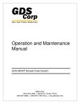
1
Operation and Maintenance
Manual
95/TX Wireless Alarm Station & Repeater
GDS Corp.
2513 Hwy 646 Santa Fe, Texas 77510
409-927-2980 409-927-4180 (Fax) www.gdscorp.com
95/TX Operation & Maintenance Manual, Revision 1.0
CAUTION: FOR SAFETY REASONS THIS EQUIPMENT MUST BE OPERATED AND SERVICED BY QUALIFIED
PERSONNEL ONLY. READ AND UNDERSTAND INSTRUCTION MANUAL COMPLETELY BEFORE OPERATING
OR SERVICING.
ATTENTION: POUR DES RAISONS DE SÉCURITÉ, CET ÉQUIPEMENT DOIT ÊTRE UTILISÉ, ENTRETENU ET
RÉPARÉ UNIQUEMENT PAR UN PERSONNEL QUALIFIÉ. ÉTUDIER LE MANUE D’INSTRUCTIONS EN ENTIER
AVANT D’UTILISER, D’ENTRETENIR OU DE RÉPARER L’ÉQUIPEMENT.
REVISION HISTORY
Revision 1.0
3/1/14 Initial Release
Copyright © 2014 GDS Corp. All Rights Reserved
P/N 1200-0739-01
Page 2
95/TX Operation & Maintenance Manual, Revision 1.0
CONTENTS
1
SAFETY INFORMATION _______________________________________________ 5
FOR YOUR SAFETY __________________________________________________________________ 5
WARRANTY _______________________________________________________________________ 5
IF YOU HAVE QUESTIONS ____________________________________________________________ 5
2
GDS CORP WIRELESS SYSTEM OVERVIEW ________________________________ 6
GDS Corp Wireless Devices ___________________________________________________________ 7
Key Features_______________________________________________________________________ 8
3
95/TX HARDWARE ___________________________________________________ 9
4
INSTALLATION _____________________________________________________ 11
Choosing a Location ________________________________________________________________ 11
Power and Signal Wiring ____________________________________________________________ 13
Antenna selection _________________________________________________________________ 14
5
SETUP & OPERATION ________________________________________________ 17
User Interface ____________________________________________________________________ 17
Network Setup ____________________________________________________________________ 18
Channel Setup ____________________________________________________________________ 19
Alarm Device Setup ________________________________________________________________ 19
6
TROUBLESHOOTING GUIDE ___________________________________________ 20
7
USER MENUS ______________________________________________________ 21
8
SPECIFICATIONS ____________________________________________________ 26
9
SPARE PARTS ______________________________________________________ 27
10
DRAWINGS AND DIMENSIONS ______________________________________ 28
11
NETWORK SETTINGS ______________________________________________ 31
12
WIRELESS SYSTEM SETUP CHECKLIST _________________________________ 32
13
WIRELESS RANGE CALCULATIONS ____________________________________ 33
Page 3
95/TX Operation & Maintenance Manual, Revision 1.0
TABLE OF FIGURES
FIGURE 2-1: GDS CORP WIRELESS GAS DETECTION SYSTEM .......................................................................... 6
FIGURE 3-1: 95/TX SINGLE ENCLOSURE CONFIGURATION ............................................................................. 9
FIGURE 3-2: 95/TX ALARM STATION / REPEATER WITH LOCAL STROBE & HORN .......................................... 9
FIGURE 3-3: 95/TX ALARM STATION / REPEATER WITH RATED HORN & STROBE ....................................... 10
FIGURE 3-4: 95/TX WITH REMOTE LIGHT STACK (PRELIMINARY) ................................................................ 10
FIGURE 4-1: DC POWER INPUT WIRING ....................................................................................................... 13
FIGURE 4-2: AC POWER INPUT WIRING ....................................................................................................... 13
FIGURE 4-3: 95/TX ALARM RELAY CONNECTIONS ........................................................................................ 14
FIGURE 4-4: YAGI DIRECTIONAL ANTENNA .................................................................................................. 15
FIGURE 5-1: 95/TX DISPLAY .......................................................................................................................... 17
FIGURE 7-1: 95/TX MAIN MENU TREE .......................................................................................................... 21
FIGURE 7-2: CHANNEL CONFIGURATION MENU .......................................................................................... 22
FIGURE 7-3: SYSTEM CONFIGURATION MENU ............................................................................................. 23
FIGURE 7-4: COMMUNICATIONS MENU ...................................................................................................... 24
FIGURE 7-5: SYSTEM SECURITY MENU ......................................................................................................... 25
FIGURE 7-6: TECHNICIANS ONLY MENU ....................................................................................................... 25
FIGURE 9-1: 95/TX SPARE PARTS .................................................................................................................. 27
FIGURE 10-1: 95/TX DIMENSIONS (DC, STROBE ONLY) ................................................................................ 28
FIGURE 10-2: 95/TX DIMENSIONS (AC, NR HORN + STROBE) ....................................................................... 29
FIGURE 10-3: 95/TX DIMENSIONS (XP HORN + STROBE).............................................................................. 30
FIGURE 11-1: GDS CORP NETWORK SETTINGS ............................................................................................. 31
FIGURE 12-1: STEP-BY-STEP WIRELESS SETUP CHECKLIST ............................................................................ 32
FIGURE 13-1: RF TRANSMISSION MARGIN ................................................................................................... 33
FIGURE 13-2: RF TRANSMISSION ZONE ........................................................................................................ 34
Page 4
95/TX Operation & Maintenance Manual, Revision 1.0
1 SAFETY INFORMATION
Important – Read Before Installation
Users should have a detailed understanding of 95/TX operating and maintenance instructions. Use the
95/TX only as specified in this manual or detection of gases and the resulting protection provided may be
impaired. Read the following WARNINGS prior to use.
FOR YOUR SAFETY
•
The 95/TX wireless alarm station described in this manual must be installed, operated and
maintained in accordance with information contained herein. Installation in any hazardous area
must comply with all applicable restrictions, requirements and guidelines for said hazardous
areas. It is the end user customer’s final decision to ensure that the 95/TX is suitable for the
intended use.
•
Do not operate the 95/TX if its enclosure is damaged or cracked or has missing components.
Make sure the cover, internal PCB’s and field wiring are securely in place before applying power.
•
Do not expose the 95/TX to electrical shock or continuous severe mechanical shock. Protect the
95/TX and related assemblies from dripping liquids and high power sprays.
•
Periodically test for correct operation
•
Use only for applications described within this manual.
WARRANTY
GDS Corp. hardware products carry a 2-year limited repair or replacement warranty on electronics and
workmanship. GDS Corp. reserves the right to void warranty claims based on evidence of misuse, abuse,
or the misapplication of a specific sensor in an environment known to adversely affect sensor life.
Warranty period starts on date of shipment from GDS Corp.
IF YOU HAVE QUESTIONS
Please contact us at:
GDS Corp
2513 FM 646 Road North, Santa Fe, Texas, 77510
409-927-2980 (Office), 409-927-4180 (Fax)
[email protected]
www.gdscorp.com
Page 5
95/TX Operation & Maintenance Manual, Revision 1.0
2 GDS CORP WIRELESS SYSTEM OVERVIEW
The new GDS Corp TX-Series wide-area Wireless Gas Detection System incorporates a wealth of new
features and capabilities that make installation, setup and operation easier and faster and provides the
best in wireless personnel safety and equipment protection.
The system consists of a C2/TX Wireless Site Manager 32-point controller with WiFi, MODBUS satellite or
cellular connectivity, one or more GASMAX/TX single or dual channel battery-operated wireless gas
detectors for toxic and combustible gases and one or more 95/TX Wireless Alarm Station / Repeaters that
allow highly visible strobes or horns to be placed in locations such as gates, guard shacks or worker’s
quarters where timely indication of hazardous conditions can reduce injuries or save lives.
Network Website
Dashboard Monitor
95/TX Wireless Alarm Stations
Text Alarms & Alerts
via Smartphone
GM/TX Wireless Gas Monitors
C2/TX Wireless
Site Manager
with Data Logging
Satellite or Cellular
Remote Monitoring
Worldwide
Local WiFi
Network to
Smartphones or
Tablets
Remote MODBUS Master
Wired or Wireless Link
Figure 2-1: GDS Corp Wireless Gas Detection System
Page 6
95/TX Operation & Maintenance Manual, Revision 1.0
GDS CORP WIRELESS DEVICES
GASMAX/TX GAS MONITOR (GM/TX)
The battery-powered single or dual channel GASMAX/TX monitor uses the latest in ultralow power infrared or electrochemical sensors to sample the ambient air every six
seconds for toxic or combustibles gases. If gas is present, a gas data packet containing
level and alarm data is transmitted to any active listener device. A user programmable
‘wake-up timer’ guarantees that even if gas is not present, a transmission will occur on
predetermined intervals to notify the C2/TX controller that the detector is present and
working. For more information on the GASMAX/TX monitor see the GASMAX/TX Users
Guide (P/N 1200-0863).
C2/TX WIRELESS SITE MANGER (C2/TX)
The C2/TX Wireless Site Manager listens for broadcast gas data packets and verifies that
transmissions are being received from all active channels. If an alarm condition exists,
the C2/TX activates local warning devices and updates its MODBUS database. An
optional cellular or satellite remote access system reads changes in the MODBUS
database and transmits alarm information to a cloud server which, in turn, sends
ALARM
STATUS
CLEAR
text messages or email warnings and alerts. The C2/TX also acts as the Beacon
Server for the entire system, transmitting a broadcast signal that all radios use to
synchronize their transmissions. For more information on the C2/TX Wireless Site
Manager, see the C2/TX Users Guide (P/N 1200-0866).
95/TX WIRELESS ALARM STATION (95/TX)
The 95/TX Wireless Alarm Station also listens for gas data packets broadcast by
GASMAX/TX monitors and activates local horns or strobes if an alarm condition
exists. In addition, the 95/TX can also be programmed to retransmit (“repeat”)
each received gas data packet. Finally, if required by network topology, a 95/TX
alarm station can be programmed to act as the Beacon Server for the network.
This might be appropriate if the 95/TX is mounted on a pole or other ‘high point’
that provides better line-of-sight communications with all GASMAX/TX monitors,
C2/TX controllers and other 95/TX alarm stations. This manual contains information on the 95/TX
Wireless Alarm Station.
Page 7
95/TX Operation & Maintenance Manual, Revision 1.0
KEY FEATURES
BATTERY-POWERED COMBUSTIBLE MONITORS
In addition to standard low-power electrochemical sensors, the new GASMAX/TX supports an ultra-low
power infrared detector for methane, propane, general hydrocarbons as well as carbon dioxide gas. Dualchannel GASMAX/TX monitors can be configured to measure both combustible and toxic hydrogen sulfide
gases with no external source of power.
LISTENER DEVICE AUTO-CONFIGURATION
Each GASMAX/TX gas monitor periodically broadcasts a config data packet that contains information on
tag name, engineering units, zero and span values, alarm levels and other user-adjustable settings. When
a C2/TX site manager or 95/TX alarm station receives a config data packet, setup information in the
GASMAX/TX is automatically loaded into the listener’s channel information database. This makes it
unnecessary to independently program listener devices, and allows them to announce alarms using
customer-recognizable tag names such as “North Fence” or “Drillers Shack” previously programmed into
the individual GASMAX/TX monitor.
REMOTE ACCESS
The C2/TX Wireless Site Manager can be optionally configured for satellite or cellular remote access
packages. These packages include a dedicated satellite or cellular modem with optional GPS receiver,
antenna cable, lightning arrestor and antenna, and are custom programmed to query the C2/TX Modbus
database and transmit alarm and event data to network-based servers that display the information on a
“dashboard” display. Users can setup the dashboard to automatically generate emails, text messages or
cellular phone calls in the event of a gas alarm or maintenance event.
ADVANCED RF TECHNOLOGY
GDS Corp wireless products use 900 MHz or 2.4 GHz RF modems based on Frequency Hopping Spread
Spectrum (FHSS) technology. FHSS radios offers longer range and higher power than those found in typical
mesh networks. In the United States, Canada and selected other countries, 900 MHz is recommended due
to increased power output available (up to 1 watt), greater range and ability of lower frequency signals to
travel around interfering objects. Systems utilizing 2.4 GHz are license-free in most areas of the world and
tend to be less susceptible to interference from existing radio frequency sources.
Page 8
95/TX Operation & Maintenance Manual, Revision 1.0
3 95/TX HARDWARE
The GDS Corp 95/TX Wireless Alarm Station is available in a number of different configurations that
include rated and non-rated horns and strobes as well as remote two, three or four strobe light stacks
with optional horn sounder. Dimensions and mounting recommendations are shown in Appendix X.
The 95/TX repeater-only or repeater plus strobe configuration includes a single NEMA 7 enclosure as
shown in Fig 3-1. DC input power can range from +12 to +30VDC.
95/TX configured
for repeater with
local strobe
(+12-30 VDC)
95/TX
configured for
repeater
function only
(+12-30 VDC)
Strobe colors
include:
RED
YELLOW
BLUE
PURPLE
DC Power
Input
Figure 3-1: 95/TX Single Enclosure Configuration
If the 95/TX configuration includes an AC power supply or horn sounder, the device is configured using
two NEMA 7 enclosures as shown in Fig 3-2. The optional AC power supply is located in the left-side
enclosure. Input power is limited to +12VDC, +24VDC or 110/220VAC only.
95/TX
configured
with local NR
strobe and
horn
(+12 VDC,
+24 VDC or
110/220 VAC)
Strobe colors
include:
RED
YELLOW
BLUE
PURPLE
AC or DC
Power Input
Figure 3-2: 95/TX Alarm Station / Repeater with Local Strobe & Horn
Page 9
95/TX Operation & Maintenance Manual, Revision 1.0
Figure 3-3 shows the same configuration with Class 1 Division 2 rated strobe and Class 1 Division 2 rated
horn. Input power is limited to +12VDC, +24VDC or 110/220VAC only.
95/TX configured
with local rated
strobe and horn
(+12 VDC,
+24 VDC or
110/220 VAC)
Strobe colors
include:
RED
YELLOW
BLUE
PURPLE
AC or DC
Power Input
Figure 3-3: 95/TX Alarm Station / Repeater with Rated Horn & Strobe
The 95/TX Alarm Station / Repeater is also available with remote two strobe, two strobe plus horn, three
strobe and three strobe plus horn combinations (See Figure 3-4). Contact GDS Corp for more details.
Strobe colors
include:
RED
YELLOW
BLUE
PURPLE
DC Power
Input
Figure 3-4: 95/TX with Remote Light Stack (Preliminary)
Page 10
95/TX Operation & Maintenance Manual, Revision 1.0
4 INSTALLATION
CHOOSING A LOCATION
The most important role of an Alarm Station is to provide real-time
warning of hazardous conditions that may be present in the vicinity.
Distance from antenna to
nearest metallic surface:
900 MHz => 24” Minimum
2.4 GHz => 6” Minimum
As a result, it is important to install the 95/TX such that the strobe
and/or warning horn provide maximum coverage for the warning area.
At the same time, consideration must be given to the following
conditions: 1) ability to receive gas data packets from all GASMAX/TX
wireless gas detectors; 2) access to a continuous source of AC or DC
power, and 3) maintaining a minimum distance between the antenna
and closest metallic object, or any object that creates RF interference
such as high voltage power lines or large sodium or mercury vapor
Distance above ground:
6’ / 2m recommended
lamps. The minimum spacing distance is determined by the RF
frequency chosen and is shown below.
MOUNTING THE 95/TX (Single Enclosure)
The 95/TX standard enclosure is a single cast aluminum explosion-proof
(NEMA 7) enclosure that has two 0.27” diameter mounting holes spaced
5.0” apart. If a local strobe is attached, the strobe body extends 0.5”
5.0”
behind the plane of the enclosure. If the 95/TX is to be mounted on a flat
plate, then spacers must be installed between the enclosure mounting
holes and the plate to allow for clearance between the strobe and
backplate. Furthermore, if the 95/TX is plate-mounted, the plate should
be designed such that the antenna extends above the plate into free
space. Power to the unit should be brought through the left-hand side
¾” NPT threaded opening using an appropriate fitting (not provided).
For pole mount applications, GDS Corp offers a pole mounting kit
(P/N 20-0165) that contains a pre-drilled plate, stainless steel mounting
bolts and two stainless steel U-bolt assemblies. The pole mounting kit
supports poles up to 2.0” in diameter.
Page 11
9.5”
95/TX Operation & Maintenance Manual, Revision 1.0
In all cases, the 95/TX enclosure must be properly connected to earth
ground to maximize radio reception and as protection against electrical
discharge and lightning strikes.
MOUNTING THE 95/TX (Dual Enclosure)
If the 95/TX configuration includes either a horn or AC power supply,
the unit consists of two enclosures mounted side by side as shown at
right. There are four 0.27” diameter mounting holes spaced as shown.
6.0”
The optional AC supply is always mounted in the left-hand side
enclosure and AC or DC power enters through the lower left side ¾”
NPT threaded opening using an appropriate fitting (not provided).
Both the horn and strobe extend rearward past the plane of the
mounting holes by 0.5” so if the unit is to be plate mounted, then
5.0”
appropriate spacers must be installed between the enclosure
mounting holes and plate to allow for clearance between the
backplate and strobe and horn. If mounting the unit on a plate, be sure
that the antenna extends above the plate into free space.
The dual-enclosure unit can also be mounted using the
p/n 20-0165 pole-mounting kit as shown at right. For best
protection against lightning or electrical discharge, make
sure the pole is buried at least 3’ into the ground or is
properly bonded to earth ground using large diameter
wire or braided cable. If the pole extends above the level
of the antenna as shown, the pole will provide some
additional protection against direct lightning strikes.
Page 12
17”
95/TX Operation & Maintenance Manual, Revision 1.0
POWER AND SIGNAL WIRING
DC POWER
When using a source of 24VDC, the power and ground connections are made to the right-hand side
terminal block (TB1) on the 95/TX I/O power supply board located in the back of the enclosure.
+12-30 VDC Input
TB1
-
Figure 4-1: DC Power Input Wiring
AC POWER
When using a source of AC power, the line, neutral and earth ground connections are made to AC power
supply located in the left-hand side enclosure. A cable gland is provided to run the power wiring out the
lower left side enclosure opening.
Line
Neutral
Ground
Figure 4-2: AC Power Input Wiring
Page 13
95/TX Operation & Maintenance Manual, Revision 1.0
CONNECTING ALARM DEVICES
The 95/TX provides three SPDT alarm relay outputs and one dedicated fault relay output. Terminals are
labeled “NO” (normally open), “NC” (normally closed) and “C” (common) and are located on the power
supply board located in the back of the enclosure. The power supply board also provides contacts for a
remote “alarm acknowledge” button. Power for 24V strobes or horns can be taken from spare “+” and “-“
pins on TB1.
Relay 1
Relay 3
Fault Relay
Relay 2
Figure 4-3: 95/TX Alarm Relay Connections
ANTENNA SELECTION
MONOPOLE AND COLLINEAR OMNI-DIRECTIONAL ANTENNAS
The 95/TX Wireless Alarm Station includes a standard “rubber duck” omnidirectional antenna. “Omni”
antennas are the most commonly used antenna for portable and semi-portable equipment. When
mounted vertically, they provide good all-around (“omnidirectional”) reception and transmission from
horizontal directions, and are generally rugged and when sealed properly against moisture can provide
years of quality service.
The 95/TX is also available with a flexible omnidirectional antenna that is more resistant to damage in
field applications. The flexible antenna offers the same gain and reception pattern.
Collinear antennas are similar in appearance to ‘rubber duck’ antennas, but are more sophisticated and
combine several vertical antennas that operate in parallel to increase signal gain by focusing the reception
pattern in a more horizontal plane. Collinear antennas should be used where additional signal gain is
required.
Page 14
95/TX Operation & Maintenance Manual, Revision 1.0
YAGI DIRECTIONAL ANTENNAS
Yagi antennas are directional along the central beam of the antenna. The folded element is towards the
back and the antenna should be “pointed” in the direction of the transmission. Yagi antennas should also
be mounted with at least 2-3’ of clearance from other objects. Mount the Yagi antenna as shown for
maximum RF transfer.
Always mount Yagi antennas with the
primary elements oriented in the same
direction as any omnidirectional
antennas in the same system
Figure 4-4: Yagi Directional Antenna
In networks spread over wide areas, it is common for a central receiver / controller to have an omnidirectional antenna (such as a collinear) and the remote GAMAX/TX monitor to have Yagi directional
antennas. Care should to be taken to ensure the Yagi is aligned correctly to achieve optimum
performance.
COAXIAL CABLES
When installing a coaxial cable between the 95/TX and a remote antenna, constructing a loop of cable
below the antenna is always recommended. The loop allows water to drip off the bottom of the U
instead of into the connection, reduces installation strain and provides spare cable length in case later the
original connectors need to be replaced.
Avoid installing coax cables together in long parallel paths. Leakage from one cable to another has a
similar effect as mounting an antenna near another antenna.
SURGE PROTECTION & GROUNDING
Voltage surges primarily enter the 95/TX Alarm Station via the antenna connection as a result of electrical
discharge in the atmosphere. Electrical energy follows the most direct path to earth and the best
protection is achieved by “draining” the surge energy to earth via an effective earth ground. Wireless
Page 15
95/TX Operation & Maintenance Manual, Revision 1.0
devices should have a solid connection to earth via a ground stake or ground grid if the soil has poor
conductivity. Solid connection means a large capacity conductor (not a small wire) with no coils or sharp
bends. All other devices connected to the 95/TX, such as remote strobes or horns, should be grounded to
the same ground point if possible. There can be significant resistance between different ground points
leading to very large voltage differences during lightning activity.
It is very difficult to protect against direct lightning strikes but the probability of a direct strike at any one
location is very small. Unfortunately, power line surges and electromagnetic energy in the air can induce
high voltage surges from lightning activity several miles away.
SEALING ANTENNA AND CABLE FITTINGS
If a coax cable connects to the antenna via connectors, it is very important to weatherproof the
connection using #1000-2314 or equivalent sealing tape. Moisture ingress into a coax cable connection is
the most common cause of problems with antenna installations. A three layer sealing process is
recommended – an initial layer of electrical PVC tape, followed by a second layer of self-vulcanizing
weatherproofing tape (#1000-2314), with a final layer of electrical PVC tape.
USE IN HAZARDOUS AREAS
The 95/TX enclosure is certified for use in Class 1 Division 1 hazardous areas. The standard 10-0295
rd
antenna coupler is designed to meet Class I Division 2 hazardous area standards but is not 3 party
certified.
Page 16
95/TX Operation & Maintenance Manual, Revision 1.0
5 SETUP & OPERATION
USER INTERFACE
There are four magnetic switches on the face of the 95/TX, arranged in a quadrant around the LCD
display labeled “NEXT”, “EDIT”, “DOWN/TEST” and “UP/ACK”. To activate, or “press” a magnetic switch,
swipe the magnet near the switch. To access the Main Menu, press the “EDIT” key. While in the menu
display, use the UP and DOWN keys to select an item, EDIT to change an item, and NEXT to exit the menu.
NOTE: HOLDING A MAGNET OVER THE DN/TEST KEY WILL ACTIVATE (TEST) ALL ALARM RELAYS
When power is applied to the 95/TX, the display will show one of two messages – “Alarm Status Clear” if
the 95/TX has identified and locked onto the network beacon, or “No Server Found”, indicating that the
beacon signal is either too weak OR the network selection (“A” through “Z”) is not programmed to match
the current network.
Figure 5-1: 95/TX Display
Once programming is complete and the beacon server is ‘in range’, the “Alarm Status Clear’ message will
be displayed until an alarm event occurs. This includes both gas alarms as well as communications errors
caused by missing gas data packet information.
An icon on the right-hand side of the screen indicates the status of the beacon server and can be useful
when troubleshooting network issues:
Beacon in Range
Normal Operation
Beacon Not in Range
Check network settings
Page 17
Beacon In Range but
was previously lost:
Intermittent beacon
signal; check network
S
E
R
V
E
R
95/TX configured
as only network
beacon server
95/TX Operation & Maintenance Manual, Revision 1.0
NETWORK SETUP
Integrating the 95/TX Wireless Alarm Station into a GDS Corp network requires adjustment of the
following network device settings. Systems shipped from GDS Corp will already have these settings preprogrammed.
NETWORK ID
All devices on a single GDS Corp wireless network must share the same Network ID. The Network ID
parameter combines the definition of a unique “System ID”, the selection of a set of operating
frequencies and the use (or not) of data encryption algorithms when transmitting and receiving data. See
Chapter 12 for a complete definition of network parameters defined by each Network ID. Data
transmission on networks “A” through “L” are non-encrypted, while data transmission on networks “M”
through “Z” are encrypted in software. There is no performance penalty associated with an encrypted
network selection.
To select the Network ID, press “EDIT” to access the main menu, and then select “Communications” and
“Network ID”. If the selected Network ID matches that programmed into the primary Beacon Server, the
“Alarm Status Clear” message will appear.
RF MODE
Mode determines if the 95/TX is defined as the “Beacon Server”. In any GDS Corp network, one device
acts as the beacon server, transmitting a continuous signal that allows each wireless device to synchronize
its own transmission while minimizing power consumption. If the 95/TX is set for “Client”, then no beacon
is transmitted; if set for “Server”, the 95/TX will broadcast the beacon signal.
NOTE: ONLY ONE DEVICE IN ANY GIVEN NETWORK SHOULD BE PROGRAMMED AS THE BEACON SERVER.
In some cases, it may be advantageous for a 95/TX to act as the beacon server, if the C2/TX controller is
mounted inside a building or structure and the 95/TX alarm station is mounted outside and above ground
level. In this case, a beacon transmitted by the 95/TX may have a better chance of reaching the remote
GASMAX/TX monitors. In this case, be sure that the C2/TX Client/Server setting is set to “Client”.
To select Client or Server, press “EDIT” to access the main menu, and then select “Communications” and
“RF Mode”. Remember, only one device in any given network should be set as the “Beacon Server”.
Page 18
95/TX Operation & Maintenance Manual, Revision 1.0
RF POWER
Systems that operate on 900 MHz offer adjustable power levels, from 10 mW up to 1.0 Watt. Unless there
are other GASMAX/TX monitors located in close proximity to the 95/TX, GDS Corp recommends setting
the power level to 1.0 Watt.
To select the power level, press “EDIT” to access the main menu, and then select “Communications” and
“TX Power”. Power levels in systems that utilize 2.4 GHz radios cannot be adjusted.
CHANNEL SETUP
The next step after the 95/TX is successfully integrated into the wireless network is to setup the total
number of active channels and enable individual channels assigned to each remote GASMAX/TX gas
monitor.
ACTIVE CHANNELS
Set the total number of channels (From “1” to “32”) that the 95/TX needs to monitor by selecting “Edit”
followed by “System Config” and then “Active Channels”. Press “EDIT” to modify the setting.
INDIVIDUAL CHANNEL SETUP
Once the total number of channels is set, activate each channel that will be associated with an individual
GASMAX/TX gas monitor. You will need to know the Remote ID of each GASMAX/TX monitor. Dual
channel devices will have two device ID settings; this will allow the 95/TX to individually monitor and
alarm on each channel separately.
For each monitored channel, the 95/TX can be programmed to “repeat”, or re-broadcast each received
gas data packet. This is useful if the 95/TX is located between the GASMAX/TX monitor and C2/TX
controller, or if the gas data packet needs to be repeated to other 95/TX alarm stations located in remote
areas.
To enable a specific channel and set the Device ID and Repeat Packet parameters, press “EDIT” followed
by “Channel Config”.
ALARM DEVICE SETUP
Once the network and channel parameters are set properly, program each relay to activate based on
alarm data from specific channels. For more information on relay setup, see the User Menu section on
relays.
To program each relay, press “EDIT”, followed by “System Config” and then select “Relay Config”.
Page 19
95/TX Operation & Maintenance Manual, Revision 1.0
6 TROUBLESHOOTING GUIDE
DISPLAY SCREEN SHOWS “NO SERVER FOUND”
•
95/TX located too far from beacon server; move closer
•
95/TX network ID not set to match network ID of primary beacon server; match Network IDs
•
95/TX antenna or antenna cable broken or damaged; repair or replace
•
Radio type incorrect (using 900 MHz radio in 2.4 GHz network or vice-versa)
IN-RANGE ICON SHOWS DOTTED LINE
•
Beacon server signal lost and regained; check communications
EVENT LOG SHOWS SINGLE CHANNEL IN COMM ERROR
•
GASMAX/TX battery dead; replace battery
•
GASMAX/TX too far from beacon server or too far from 95/TX; move closer
EVENT LOG SHOWS ALL CHANNELS IN COMM ERROR
•
Network ID set incorrectly; check Network ID
•
Beacon server unavailable; check device designated as beacon server
•
Lightning strike on antenna or in vicinity; replace radio
CHANNEL SHOWS CONFIG PENDING
•
This is normal – config data is broadcast by each GASMAX on 8 hour intervals. If condition
persists for more than 24 hours, check GASMAX/TX Wakeup Timer setting.
DISPLAY SCREEN BLANK
•
DC power failed or too low
•
AC power unavailable or AC power supply failure
Page 20
95/TX Operation & Maintenance Manual, Revision 1.0
7 USER MENUS
The 95/TX Main Menu tree is shown below. To access the Main Menu, swipe the magnetic wand over the
EDIT key. Use the UP and DN keys to select an item and press EDIT. Use NEXT to exit a menu.
ALARM
STATUS
CLEAR
“EDIT”
01 MEASUREMENT NAME
(Alarm 1)
02 MEASUREMENT NAME
(Alarm 1)
CHANNEL CONFIG
Select Channel
Channel Active
Remote ID
Repeat Packet
02
YES
02
YES
SYSTEM CONFIG
Relay Config
Active Channels
Contrast
Relay Refresh
16
0m
900 MHz Radio
Network
A
RF Mode
CLIENT
TX Power
10mW
MAIN MENU
Channel Config
System Config
Communications
Security
Technicians ONLY
Ver 1.00
RELAY CONFIG
Relay
1
Relay 1 Tag Name
Trip On
Alarm 1
Failsafe
NO
Acknowledge
NO
Select Channels
1
2
3
4
5
6
7
8
X
X
X
X
X
X
X
X
9
10
11
12
13
14
15
16
X
X
X
X
X
X
X
X
17
18
19
20
21
22
23
24
X
X
X
X
X
X
X
X
25
26
27
28
29
30
31
32
X
X
X
X
X
X
X
X
CONTRAST
UP/ DOWN to change
Next to Exit
Server In Range
WaveNet Radio
SYSTEM SECURITY
Contact Name
Pass Code
xxxx
UNLOCKED
Enter key sequence
to access menu
* * * *
NEXT key to Exit
TECHNICIANS MENU
Relay Test
RELAY TEST
Relay
Relay
Relay
Relay
Figure 7-1: 95/TX Main Menu Tree
Page 21
1
2
3
4
OFF
OFF
OFF
OFF
R
L
Y
1
A
L
1
95/TX Operation & Maintenance Manual, Revision 1.0
CHANNEL CONFIGURATION MENU
The Channel Configuration menu contains settings that are unique to each channel. There are two
channels and each menu contains identical entries.
CHANNEL CONFIG
Select Channel
Channel Active
Remote ID
Repeat Packet
02
YES
02
YES
Figure 7-2: Channel Configuration Menu
SELECT CHANNEL – Use the EDIT key to select the channel to configure.
NOTE: WHEN EDITING CHANNEL INFORMATION, MAKE SURE TO SELECT THE CORRECT CHANNEL MENU
BEFORE MAKING CHANGES.
CHANNEL ACTIVE – Set for YES if this channel is to be used to monitor a remote gas detector.
REMOTE ID – Set to match the Remote ID of the specific GASMAX/TX gas monitor associate with this
channel.
NOTE: ALTHOUGH NOT REQUIRED, GDS CORP RECOMMENDS MAINTAINING A 1:1 RELATIONSHIP
BETWEEN THE GASMAX/TX DEVICE ID AND 95/TX CHANNEL SELECTION. IN OTHER WORDS, IF THE
GASMAX / TX DEVICE ID IS 5, THEN ASSIGN THAT GASMAX/TX TO CHANNEL 5 ON THE 95/TX, EVEN IF
CHANNELS 2, 3 AND 4 ARE NOT USED.
REPEAT PACKET – Set for YES if the 95/TX should rebroadcast (“repeat”) the data packet received from
the assigned GASMAX/TX gas monitor. This is useful if the GASMAX/TX is located farther away from the
main controller. Default is “NO” and must be enabled if the repeat function is desired.
A “Comm Error Timeline” is shown in the bottom of the screen that indicates time since the last received
transmission for this channel. Each time a gas data packet is received, the upper arrow indicator is moved
to the far left, and then slowly moves to the right. If the arrow reaches the far right hand side of the
screen, a Comm Error is generated for this channel.
Page 22
95/TX Operation & Maintenance Manual, Revision 1.0
SYSTEM CONFIGURATION MENU
The System Configuration menu contains items that are system dependent.
SYSTEM CONFIG
Relay Config
Active Channels
Contrast
Relay Refresh
16
0m
RELAY CONFIG
Relay
1
Relay 1 Tag Name
Trip On
Alarm 1
Failsafe
NO
Acknowledge
NO
Select Channels
1
2
3
4
5
6
7
8
X
X
X
X
X
X
X
X
9
10
11
12
13
14
15
16
X
X
X
X
X
X
X
X
17
18
19
20
21
22
23
24
X
X
X
X
X
X
X
X
CONTRAST
UP/ DOWN to change
Next to Exit
Figure 7-3: System Configuration Menu
RELAY CONFIG – Relay config allows the user to assign specific relays to each channel.
RELAY N – selects the specific relay programming to modify.
RELAY N TAG NAME – Allows the user to assign a name to a specific relay. Examples include “Horn” or
“Red Strobe”.
TRIP ON – Assigns the relay to one of several alarm events: “Alarm 1”, “Alarm 2”, “Alarm 3”,
“Fault/Comm” or “Any Alarm”.
FAILSAFE – Activates the relay in ‘no-alarm’ conditions such that the relay drops out when the alarm
occurs. Use caution when setting relays for FAILSAFE if unit is running on solar or battery power.
ACKNOWLEDGE – Clears the alarm relay condition if the UP/ACK button is pressed.
NOTE: WHEN EDITING RELAY INFORMATION, MAKE SURE TO SELECT THE CORRECT RELAY MENU BEFORE
MAKING CHANGES.
ACTIVE CHANNELS - Sets the total number of channels available. Setting this number to match the total
number of gas detectors in a system minimizes the need to configure unused channels.
CONTRAST - Select the LCD contrast command and use the UP or DOWN to adjust the contrast of the LCD
display.
RELAY REFRESH – Sets the time interval between required alarm acknowledge actions. In other words, if
an alarm occurs and is acknowledged, and the condition persists for the programmed period of time, the
alarm relay will be reactivated and will require another ACK. Setting Relay Refresh to “0” disables this
feature.
Page 23
25
26
27
28
29
30
31
32
X
X
X
X
X
X
X
X
R
L
Y
1
A
L
1
95/TX Operation & Maintenance Manual, Revision 1.0
COMMUNICATIONS MENU
The Communications Menu is used to configure the radio modem in the 95/TX. There are two similar
menus, one for 900 MHz radios and another for 2.4 GHz radios.
900 MHz Radio
Network
A
RF Mode
CLIENT
TX Power
10mW
Server In Range
WaveNet Radio
Figure 7-4: Communications Menu
NETWORK ID - May be set from “A” through “Z” and assigns the pseudo-random radio frequency hopping
pattern and system identifier. A transmitter will not go In Range of or communicate with another
transmitter operating with a different Network Identifier. Different Network Identifiers can be used to
prevent radios in one network from listening to transmissions of another. Installations having more than
one Server network should also have different Network Identifiers for each network.
RF MODE - Determines if the device is configured to transmit the network beacon server (“SERVER”) or
listen for the network beacon from another device (“CLIENT”). Only one device in any network should be
programmed as a server.
TX POWER - Allows the user to adjust transmitter power levels if using a 900 MHz radio. Options are 10
milliwatts (mW), 200 mW, 400 mW and 1.0 Watt. Transmit power also affects the power level of the
beacon signal if the 95/TX is set as the ‘server’. Radios designed for 2.4 GHz are preset to 50 mW and
power level cannot be adjusted.
Page 24
95/TX Operation & Maintenance Manual, Revision 1.0
SYSTEMS SECURITY MENU
The System Security menu allows the user to program a four digit pass code, requiring an operator to
enter the pass code before altering any menu settings. The pass code locks the entire menu database.
SYSTEM SECURITY
Contact Name
Pass Code
xxxx
UNLOCKED
Figure 7-5: System Security Menu
CONTACT NAME - A 12 character ASCII field that is available for displaying a phone # or name of a person
or contact who knows the Pass Code. Lost Pass Codes may be recovered by entering the locked security
menu and holding the UP key for 5 seconds. The 4-digit code appears near the bottom of the screen.
TECHNICIANS ONLY MENU
The Technician’s Only menu group contains a Relay Test function that allows the user to individually
activate each of the internal relays for test purposes. Select the desired relay and hit the EDIT key to
toggle the relay between OFF and ON.
Enter key sequence
to access menu
* * * *
NEXT key to Exit
TECHNICIANS MENU
Relay Test
Figure 7-6: Technicians Only Menu
The sequence to enter the Technician’s Only menu is four “UP” keys.
Page 25
RELAY TEST
Relay
Relay
Relay
Relay
1
2
3
4
OFF
OFF
OFF
OFF
95/TX Operation & Maintenance Manual, Revision 1.0
8 SPECIFICATIONS
Power
+12-30VDC, +24VDC, +12VDC or 110/220VAC depending on configuration and
peripherals. Radio and display require 3 watts maximum.
Display
64 x128 pixel LCD with engineering units, bargraph and 30-minute trend
Input
Monitors up to 32 channels of wireless gas detection from GASMAX/TX wireless gas
detectors. Supports GDS Corp networks “A” through “Z”
Output
Four programmable SPDT relays and one dedicated fault SPDT relay. Relays are rated for
5A @ 110/220VAC or 24VDC.
Output
Rebroadcasts wireless data packets (programmable on a per-channel basis)
RF Section
(900 MHz)
Receiver sensitivity -100 dBm
Frequency range 902 to 928 MHZ.
Repeater function: User adjustable transmit power from 10 mW to 1.0 watt
RF Section
(2.4 GHz)
Receiver sensitivity -100 dBm
Frequency range from 2.406 GHz to 2.435 GHz (network identifier A – R) and from 2.444
GHz to 2.472 GHz (network identifier S – Z)
Repeater function: Fixed transmit power of 50 mW.
Temperature
Operating -40°C to +55°C
Memory
On-board non-volatile memory retains all user settings
Housing
Aluminum housing(s) with epoxy paint standard; #316 stainless steel optional
Dimensions
See dimensional drawings in Chapter 10.
Approvals
Enclosure CSA certified for Class I Division 1 hazardous areas
Warranty
Two years on electronics
Page 26
95/TX Operation & Maintenance Manual, Revision 1.0
9
SPARE PARTS
DISPLAY & ENCLOSURE
Antenna & Fittings:
1000-2189 Antenna, 900 MHz Fixed
1000-2732 Antenna, 900 MHz Spring Base
1000-2300 Antenna, 2.4 GHz Fixed
1000-2733 Antenna, 2.4 GHz Spring Base
10-0295
Antenna coupler (RP-TNC)
Display:
10-0404-R
1000-2188
1000-2454
Enclosure & Peripherals:
10-0160
95/TX Enclosure (Yellow)
12-0218
Strobe, Red (NR)
12-0219
Strobe, Amber (NR)
12-0761
Strobe, Blue (NR)
12-0833
Strobe, Purple (NR)
2000-0230 Horn, 24VDC
1200-0495 Power Supply, 110/220VAC
I/O Board:
10-0324
10-0425
Figure 9-1: 95/TX Spare Parts
Page 27
95/TX Display (no radio)
900 MHz radio module
2.4 GHz radio module
95/TX I/O (Four relays)
95/TX I/O (Five relays)
95/TX Operation & Maintenance Manual, Revision 1.0
10 DRAWINGS AND DIMENSIONS
6.7”
5.0”
20” with 900 MHz rubber duck antenna
23” with 900 MHz flex antenna
20” with 2.4 GHz rubber duck antenna
23” with 2.4 GHz flex antenna
Figure 10-1: 95/TX Dimensions (DC, Strobe Only)
Page 28
95/TX Operation & Maintenance Manual, Revision 1.0
20” with 900 MHz rubber duck antenna
23” with 900 MHz flex antenna
20” with 2.4 GHz rubber duck antenna
23” with 2.4 GHz flex antenna
6.0”
5.0”
13.0”
Figure 10-2: 95/TX Dimensions (AC, NR Horn + Strobe)
Page 29
95/TX Operation & Maintenance Manual, Revision 1.0
24” with 900 MHz rubber duck antenna
27” with 900 MHz flex antenna
24” with 2.4 GHz rubber duck antenna
27” with 2.4 GHz flex antenna
6.0”
5.0”
14.0”
Figure 10-3: 95/TX Dimensions (XP Horn + Strobe)
Page 30
95/TX Operation & Maintenance Manual, Revision 1.0
11 NETWORK SETTINGS
The set of Network Identifiers used by the 95/TX specify a combination of frequency hopping pattern,
frequency band, System ID value and whether or not the data is encrypted using a proprietary softwarebased algorithm.
NETWORK
ID
HOP
PATTERN
System
ID
Data
Encrypted?
900 MHz
Band
2.4 GHz
Band
Compatible
with previous
generation?
A
B
C
D
E
F
G
H
I
J
K
L
M
N
O
P
Q
R
S
T
U
V
W
X
Y
Z
1
2
3
4
5
6
7
8
9
10
11
12
13
14
15
16
17
18
19
20
21
22
23
24
25
26
1
2
3
4
5
6
7
8
9
10
11
12
13
14
15
16
17
18
19
20
21
22
23
24
25
26
No
No
No
No
No
No
No
No
No
No
No
No
YES
YES
YES
YES
YES
YES
YES
YES
YES
YES
YES
YES
YES
YES
902-928 MHz
902-928 MHz
902-928 MHz
902-928 MHz
902-928 MHz
902-928 MHz
902-928 MHz
902-928 MHz
902-928 MHz
902-928 MHz
902-928 MHz
902-928 MHz
902-928 MHz
902-928 MHz
902-928 MHz
902-928 MHz
902-928 MHz
902-928 MHz
902-928 MHz
902-928 MHz
902-928 MHz
902-928 MHz
902-928 MHz
902-928 MHz
902-928 MHz
902-928 MHz
2.402 - 2.478 GHz
2.402 - 2.478 GHz
2.402 - 2.478 GHz
2.402 - 2.478 GHz
2.402 - 2.478 GHz
2.402 - 2.478 GHz
2.402 - 2.478 GHz
2.402 - 2.478 GHz
2.402 - 2.478 GHz
2.402 - 2.478 GHz
2.402 - 2.478 GHz
2.402 - 2.478 GHz
2.402 - 2.478 GHz
2.402 - 2.478 GHz
2.402 - 2.478 GHz
2.402 - 2.478 GHz
2.402 - 2.478 GHz
2.402 - 2.478 GHz
2.402 - 2.478 GHz
2.402 - 2.478 GHz
2.402 - 2.478 GHz
2.402 - 2.478 GHz
2.402 - 2.478 GHz
2.402 - 2.478 GHz
2.402 - 2.478 GHz
2.402 - 2.478 GHz
Yes
Yes
Yes
Yes
Yes
Yes
Yes
Yes
Yes
Yes
Yes
Yes
No
No
No
No
No
No
No
No
No
No
No
No
No
No
Figure 11-1: GDS Corp Network Settings
Page 31
95/TX Operation & Maintenance Manual, Revision 1.0
12 WIRELESS SYSTEM SETUP CHECKLIST
Follow the sequence shown below to properly power-up a wireless gas detection system based on a single
C2/TX Wireless Site Manager, one or more GASMAX/TX Wireless Gas Monitors and one or more 95/TX
Wireless Alarm Stations.
STEP 1
Identify a central location for the C2/TX Wireless Site Manager. Install the C2/TX and remote
‘base station” antenna (if so equipped).
Install each GASMAX/TX Gas Monitor in a location where gas hazards may exist, and where the
antenna is visible from the base station antenna (if possible). Do NOT install next to sources of
RF interference such as high voltage power lines or mercury vapor lighting.
Install each 95/TX Wireless Alarm Station / Repeater in a location where alarm indication is
needed, and where the antenna is visible from the base station antenna (if possible). Do NOT
install next to sources of RF interference such as high voltage power lines or mercury vapor
lighting.
STEP 2
Apply power to the C2/TX Wireless System Manager
Select the desired network identifier (“A” through “Z”) and Select RF Mode = “Server”
If using 900 MHz radios, set the desired transmit power output. One watt is recommended.
Enable the desired number of wireless channels
Program relays / warning devices associated with each channel.
STEP 3
Apply power to each 95/TX Alarm Station
Select the network identifier (“A” through “Z”) to match the ID programmed into the C2/TX
Select RF Mode = “Client”
Enable the desired number of wireless channels
Program repeater function for desired channels
Verify “Server In Range”
Program relays / warning devices associated with each channel.
STEP 4
Turn on each GASMAX/TX gas monitor by holding a magnet over UP/ON key for several seconds
Select the network identifier (“A” through “Z”) to match the ID programmed into the C2/TX
Configure the RTU # (device ID) for a unique value
Program channel tag name (visible on C2/TX and 95/TX
Hold a magnet over the UP key to force a gas packet transmission
STEP 5
Confirm reception of wireless transmissions and valid gas detector readings on the C2/TX
Confirm reception of wireless transmissions on each 95/TX alarm station
STEP 6
Perform end-to-end test (apply gas, confirm alarms) using calibration or test gas
Figure 12-1: Step-by-Step Wireless Setup Checklist
Page 32
95/TX Operation & Maintenance Manual, Revision 1.0
13 WIRELESS RANGE CALCULATIONS
In order for reliable wireless communication to occur, transmitter power output, antenna ‘gain’ and
receiver sensitivity must exceed the ‘loss’, or attenuation experienced by radio signals as they travel
between transmitter and receiver. RF signals experience two kinds of ‘loss’ as they travel through space.
“Free space loss” is due strictly to the fact that RF signals ‘spread out’ as they propagate from a single
point source. Additionally, RF signals experience loss as a result of interference and interaction with
buildings, trees, structures and other physical barriers.
This gain or loss is measured in decibel-milliwatts (dBm)
and is a function of both distance and frequency. An
estimate of free space loss for 900 MHz and 2.4 GHz is
Free Space Loss @ 900 MHz:
-71 dBm at 300 ft., -91 dBm at 3000 ft.
Free Space Loss @ 2.4 GHz:
-80 dBm at 300 ft., -100 dBm at 3000 ft.
shown at right.
EXAMPLE POINT TO POINT GAIN CALCULATION
In a typical 2.4 GHz system shown below, for example, the transmitter power output is +21 dBm, each
antenna provides an additional gain of +3 dBm and the receiver sensitivity allows reliable reception of a
signal at -95 dBm power. Therefore, the total system gain is 21+3+3-(-95) = 122 dBm.
Antenna
Gain = +3 dBm
Antenna
Gain = +3 dBm
RF Power
+21 dBm
Receiver
Sensitivity
-95 dBm
Figure 13-1: RF Transmission Margin
Since a reliable system requires a gain margin of +20 dBm, this system will work acceptably if the total
free space loss is less than 102 dBm (122 dBm – 20 dBm). However, this theoretical calculation does not
take into account additional loses due to intervening structures or foliage.
WAYS TO MINIMIZE RF SIGNAL LOSS
One way to minimize free-space loss is to ensure that the combined height of the transmitter antenna and
receiver antenna exceeds the diameter of the “RF Transmission Zone” (see Fig. 13-2) and that at least 60%
Page 33
95/TX Operation & Maintenance Manual, Revision 1.0
of the area inside the zone should be free of obstacles. Although both 900 MHz and 2.4 GHz signals can
travel around or through most towers or buildings, structures such as large metal tanks or solid metal
buildings may attenuate the signal to the point where reception is marginal.
Raising the antenna at either end of the path will improve signal strength and reduce transmission errors.
GDS Corp recommends placing any antenna at least 6 feet above the surrounding terrain, and even more
if possible. However, note that the standard antenna transmits its maximum signal strength in a relatively
flat ‘donut-shaped’ pattern which may affect the performance of 95/TX monitors located in close
proximity to an elevated C2/TX WSM or receiver/controller.
RF Transmission Zone
Figure 13-2: RF Transmission Zone
Page 34
Combined Antenna Height
Distance
900 MHz 2.4 GHz
100 Ft
10’ / 3m
6’ / 2m
500 Ft
22’ / 7m
15’ / 5m
1000 Ft
30’/ 10m 20’ / 6m
3000 Ft
54’ / 17m N/A