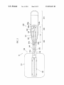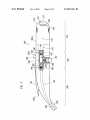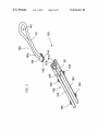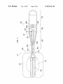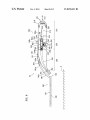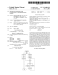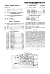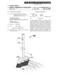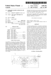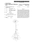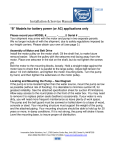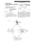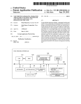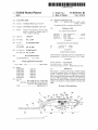
1
USOO8876421B2
(12) United States Patent
(10) Patent N0.:
Suda
(54)
US 8,876,421 B2
(45) Date of Patent:
CLEANING TOOL
(58)
Nov. 4, 2014
Field of Classi?cation Search
USPC ............ .. 401/139, 140, 251; 24/593.1, 598.5,
(75) Inventor:
Tomokazu Suda, Kagawa-ken (JP)
24/594.1; 403/375
See application ?le for complete search history.
(73) Assignee: Uni-Charm Corporation, Ehime (JP)
(56)
(*)
Notice:
References Cited
Subject to any disclaimer, the term of this
patent is extended or adjusted under 35
US: PATENT DOCUMENTS
U-S-C- 154(b)bY1096days-
(21) Appl.No.:
12/096,477
(22) PCT Filed:
Dec. 7, 2006
(86)
PCT/JP2006/324488
PCT No.:
2,990,979 A *
7/1961
Harrison et a1. ............ .. 222/482
4,013,369 A *
3/1977
Turek .......................... .. 401/139
4,954,001 A
9/1990 Billat
6,698,700 B2*
3/2004
FOREIGN PATENT DOCUMENTS
§371 (Cm),
EP
(2), (4) Datei
Sell-16,2009
JP
1602 311 A2
2004242799
(87) PCT Pub. No.: W02007/066739
_
(30)
_
English translation of First Of?ce Action from corresponding Chi
nese application N0. 2006800459482 dated Jan. 8, 2010, 19 pages.
Feb. 4, 2010
(Continued)
Foreign Application Priority Data
Dec. 9, 2005
9/2004
(Continued)
Pm" Pubhcat‘o“ Data
US 2010/0028072 A1
(51)
_
12/2005
OTHER PUBLICATIONS
PCT Pub. Date: Jun. 14, 2007
(65)
Moerke etal. ......... .. 248/22031
(Continued)
Primary Examiner i David Walczak
(JP) ............................... .. 2005-356867
14mm"! Examine/i Bradley Oliver
(74) Attorney, Agent, or Firm * Brinks Gilson & Lione
Int. Cl.
A46B 11/00
(2006.01)
(57)
A47L 13/26
A4 7L 13/46
(2006-01)
(2006-01)
With respect to a cleaning tool having a sheetlike cleaning
member for mopping a surface to be cleaned, it is intended to
A4 7L 13/20
A4 7L 13/22
(2006-01)
(2006-01)
A4 7L 13/42
(2006-01)
provide a technology effective for enhancing of cleaning
effect. There is provided cleaning tool (10) comprising clean
ing sheet (100) for mopping a surface to be cleaned and
injection nozzle (252) for jetting a cleaning liquid toward the
(52) U-s- Cl-
ABSTRACT
............... ..
surface to be cleaned at its region under the cleaning Sheet
(2013.01); A47L 13/20 (2013.01); A47L 13/22
(2013.01); A47L 13/42 (2013.01)
(100)'
USPC ......................................... .. 401/140; 401/139
18 Claims, 12 Drawing Sheets
100
110
(
- 4
If;
\
’
\
252
25]
:
‘30
DepressZ32
%_1%_1
‘20
250
230
210
US 8,876,421 B2
Page 2
(56)
References Cited
U_S_ PATENT DOCUMENTS
6,742,951 B2 *
6/2004
Schultz et a1. .............. .. 401/139
2004/0018038 A1
1/2004 Schultz et a1.
2006/0171767 A1*
8/2006 Hoadley et a1. ............. .. 401/136
2006/0171768 A1
8/2006 Hoadley et al.
FOREIGN PATENT DOCUMENTS
JP
2004305473 A
11/2004
JP
2005-533567 A
11/2005
JP
2005533567
11/2005
W0
WO 2004/008931 A1
1/2004
W0
WO 2006/113386 A2
10/2006
OTHER PUBLICATIONS
English translation of Of?ce Action from corresponding Japanese
application No. 2005-356867 dated Aug. 23, 2010, 21 pages.
European Search Report from corresponding European application
N0. 068342435 dated Jan. 14, 2014 (3 pgs).
JP
2004242799 A
JP
2004305473
9/2004
11/2004
* cited by examiner
US. Patent
NOV. 4, 2014
Sheet 1 0f 12
US 8,876,421 B2
US. Patent
NOV. 4, 2014
Sheet 2 0f 12
US 8,876,421 B2
US. Patent
NOV. 4, 2014
08
\
/
.25
\
SNNON
2a23\
2Nm2
2%
w
SN2%SN88
Sheet 3 0f 12
El
NvDENNN
3J13
2w:EN5
k
m
EN.5 F\
/
\
_
_
w
i
J>>
\
5 NaSN
.UEm
US 8,876,421 B2
2N8N8N
US. Patent
NOV. 4, 2014
Sheet 4 0f 12
US 8,876,421 B2
US. Patent
Nov. 4, 2014
Sheet 5 0f 12
120
FIG.5
US 8,876,421 B2
US. Patent
.UEN.
NOV. 4, 2014
Sheet 7 0f 12
US 8,876,421 B2
US. Patent
NOV. 4, 2014
US 8,876,421 B2
Sheet 8 0f 12
28.
2
2: mmo:
/
o: 0...Ll NmN/
d
__
2:
.UEw
Os5
\Nh%
US. Patent
NOV. 4, 2014
Sheet 9 0f 12
US 8,876,421 B2
meow
mwow
NY
Moo—
wa
NowFow\
wa
mw..3.UEm /
Vv./
Hw..-UM.E-.
OPP /
US. Patent
NOV. 4, 2014
.UE2
Sheet 10 0f 12
US 8,876,421 B2
US. Patent
NOV. 4, 2014
:.UE
Sheet 11 0f 12
US 8,876,421 B2
US. Patent
NOV. 4, 2014
2.05
Sheet 12 0f 12
US 8,876,421 B2
US 8,876,421 B2
1
2
CLEANING TOOL
uneven or stepped. The cleaning element may be of dispos
able type designed for single use, or reusable type which can
CROSS-REFERENCE TO PRIOR APPLICATION
be reused by washing. The cleaning element is typically
formed of plastic nonwoven fabric or a laminate thereof, or
resin foam. The faces to be cleaned may be either ?at or
curved, uneven or stepped.
This is a US. National Phase Application under 35 U.S.C.
§37l of International Patent Application No. PCT/JP2006/
324488 ?led Dec. 7, 2006, and claims the bene?t of Japanese
PatentApplication No. 2005-356867, ?led Dec. 9, 2005, both
of them are incorporated by reference herein. The Interna
tional Application was published in Japanese on Jun. 14, 2007
The holding part in this invention is con?gured to be
attached to the cleaning element and designed to detachably
hold the cleaning sheet. Thus, the cleaning element can be
removed from the holding part and replaced with new one as
necessary depending on the degree of dirt of the cleaning
as WO 2007/066739 Al under PCT Article 21(2).
element.
The grip in this invention is con?gured as an elongate part
FIELD OF THE INVENTION
to be held by a user. The user can hold the grip and perform a
wiping operation by the cleaning element. Further, prefer
The present invention relates to a cleaning tool, and more
particularly to a cleaning tool having a sheet-type cleaning
element for wiping a region to be cleaned inside a room or a
vehicle and so on.
BACKGROUND OF THE INVENTION
20
Various types of cleaning tools having a sheet-type clean
ing element for wiping a region to be cleaned are known. For
example, Japanese non-examined laid-open Patent Publica
tion No. 2004-242799 discloses a cleaning tool in which an
25
agent permeating bottom part is provided on the bottom of a
cleaning frame and the cleaning sheet is wrapped around the
agent permeating bottom part. In this known cleaning tool, in
use for wiping, the cleaning sheet is dampened with a clean
ing agent which is sprayed from above the agent permeating
bottom part during cleaning operation. Such a cleaning tool is
30
ably, the cleaning element may have a rectangular shape, and
the long side of the rectangular cleaning element is designed
to extend along the length direction of the elongate grip. With
this construction, the ef?ciency of user’s wiping operation
can be easily improved.
The connecting part in this invention is disposed between
the holding part and the grip and designed to ?xedly connect
the holding part and the grip. Speci?cally, the holding part
and the connecting part are ?xedly connected together, and
the grip and the connecting part are ?xedly connected
together. Thus, as a whole, the holding part, the connecting
part and the grip are integrally ?xed to each other. In this case,
two or all of the holding part, the connecting part and the grip
may be integrally molded, or all of them may be separately
molded and thereafter ?xedly connected together. The struc
capable of wiping off tough dirt on a ?oor surface which is
ture of “?xedly” connecting the holding part and the grip in
this invention only requires that the holding part and the grip
dif?cult to remove with a dry cleaning sheet. However, in
are integrally ?xed or retained at least during use of the
designing a cleaning tool of this type having a sheet-type
cleaning element, a technique for further enhancing the clean
ing effect is desired.
cleaning tool. Therefore, it includes not only a structure in
35
which relative movement at the connection between the hold
ing part and the connecting part or at the connection between
the grip and the connecting part is disabled, but also widely
includes a movable structure in which relative movement at
DISCLOSURE OF THE INVENTION
Problems to be Solved by the Invention
40
It is, accordingly, an object of the present invention to
provide an effective technique for enhancing the cleaning
effect in a cleaning tool having a sheet-type cleaning element
for wiping a face to be cleaned.
45
Means for Solving the Problems
these connections is temporarily enabled. With regard to this
movable structure, speci?cally, a hinge mechanism and a
locking mechanism can be provided at the connection
between the holding part and the connecting part or at the
connection between the grip and the connecting part. The
angle between the holding part and the connecting part or the
angle between the grip and the connecting part can be
adjusted via the hinge mechanism before and after use of the
cleaning tool, and it can be locked or retained at a predeter
mined angle by the locking mechanism during use of the
cleaning tool.
The above-described problem canbe solved by the features
of the claimed invention. This invention can be applied to the
50
The cleaning liquid supply part in this invention has a
supply noZZle for supplying cleaning liquid toward the face to
construction of cleaning tools having a sheet-type cleaning
element for wiping faces to be cleaned (?oors, walls, ceilings,
be cleaned, and is disposed on at least one of the holding part,
external walls, furniture, clothes, curtains, bedding, home
the grip and the connecting part. The “cleaning liquid” here
electric appliances, etc.) inside and outside of houses, apart
ments, buildings, factories, vehicles, etc. or faces of human
body parts to be cleaned.
The above-described problem canbe solved with the clean
ing tool according to this invention. The cleaning tool
55
polishing wax-containing cleaner, a fragrance-containing
cleaning liquid, a deodorant-containing cleaning liquid, or
dilution of any of those liquids with water, or water itself can
be used as the cleaning liquid. Further, as the manner of
includes at least a cleaning element, a holding part, a grip, a
connecting part and a cleaning liquid supply part.
widely includes liquids which can be used for cleaning opera
tion of removing dirt. Typically, a cleaner for cleaning ?oor, a
60
“supplying cleaning liquid”, a supply manner of injecting or
The cleaning element of this invention is designed as a
jetting cleaning liquid or spraying it in an atomized state, or a
sheet-type cleaning element for wiping a face to be cleaned.
supply manner of dropping cleaning liquid can be used, pro
vided that the cleaning liquid is supplied not via the cleaning
The “sheet-type cleaning element” here widely includes
those having a plate-like form in the state in which it is
attached to or detached from the holding part, which plate
like form is considerably longer and wider than is thick. The
surface of the cleaning element may be either ?at or curved,
element but directly onto the face to be cleaned. Further, in
65
this invention, the cleaning liquid supply part may be
mounted on any one of the holding part, the grip and the
connecting part, or it may be mounted to extend on more than
US 8,876,421 B2
4
3
one of the holding part, the grip and the connecting part. Once
the face to be cleaned onto which the cleaning liquid has been
Preferably, further in terms of the direction of installation
height, the supply nozzle of this cleaning tool may be located
supplied is wiped with the cleaning element, the cleaning
above a sheet lower surface of the cleaning element and in a
element can be used as a wet-type cleaning element with a
height region in which an extension line of the holding part
intersects with an extension line of the connecting part. In
damp sheet surface. In a cleaning operationusing the cleaning
element without supplying the cleaning liquid on the face to
other words, preferably, the supply nozzle may be located
below the grip and rearward of the connecting part, and above
be cleaned, naturally, the cleaning element can also be used as
a dry-type cleaning element with a normally dry sheet sur
face.
Further, as for the speci?c construction of the cleaning
liquid supply part, for example, the construction which uses a
a sheet lower surface of the cleaning element and in a height
region in which an extension line of the holding part intersects
with an extension line of the connecting part.
With this construction, when the cleaning element is in
contact with the face to be cleaned, the supply nozzle can be
prevented from interfering with the face to be cleaned. Fur
pump mechanism to pressurize cleaning liquid and discharge
the pressurized cleaning liquid to the supply nozzle, the con
struction of aerosol type which supplies pressurized cleaning
ther, the supply nozzle can be located as close as possible to
the face to be cleaned, so that the cleaning liquid can be
reliably and promptly supplied onto a desired region on the
face to be cleaned.
liquid to the supply nozzle by using gas pressure, the con
struction which causes cleaning liquid to drop from the sup
ply nozzle under its own weight, and the construction which
supplies cleaning liquid to the supply nozzle after the clean
ing liquid is pressurized in a cleaning liquid supply source
outside the cleaning liquid supply part, can be appropriately
used. Further, the cleaning liquid supply part may be con?g
Preferably, the cleaning liquid supply part of this cleaning
tool may be con?gured to supply the cleaning liquid from the
20
ured to include a region which stores cleaning liquid and a
path through which the cleaning liquid ?ows, or to include
only a region through which cleaning liquid ?ows after the
ing element can be moved downward and used for a wiping
25
cleaning liquid is supplied from the cleaning liquid supply
source located outside the cleaning liquid supply part.
Further, in this invention, an extension line in a length
direction of the grip intersects with a normal to a sheet plane
of the cleaning element at a predetermined angle. With this
construction and with the construction in which the holding
30
part, the connecting part and the grip are integrally ?xed to
each other, the cleaning tool of this invention is designed
speci?cally as a hand-held cleaning tool of which length from
the grip to the holding part via the connecting part is limited
curve of the connecting part at a predetermined point can be
de?ned as the extending direction of the connecting part.
With the construction in which the orientation of the supply
nozzle conforms to the extending direction of the connecting
part, the operation of supplying a cleaning liquid to the face to
be cleaned and the operation of wiping with the cleaning sheet
40
can be facilitated.
the cleaning tool with one hand for cleaning operation.
With this construction, dirt and dust which are stuck to the
face and dif?cult to wipe off with a dry-type cleaning element
area with the cleaning element. Particularly, in this invention,
the cleaning liquid is supplied directly onto the face to be
cleaned, so that the cleaning effect of the cleaning liquid itself
In the cleaning tool, preferably, the cleaning liquid supply
part may include a pump mechanism that pressurizes clean
ing liquid by user’ s manual operation of an operation part and
then discharges the pressurized cleaning liquid to the supply
45
nozzle. As the pump mechanism, a mechanical pump mecha
50
user’s manual operation of the operation part, or an electric
pump mechanism which is actuated by a driving force of an
electric motor, which electric motor is driven in conjunction
with the user’s manual operation of the operation part, can be
nism which is actuated by using a pressing force applied in the
can be maximized. Therefore, compared with a cleaning tool
in which cleaning liquid is supplied not onto the face to be
cleaned but to the cleaning element, this construction is
advantageous and effective in improving the cleaning effect.
In the above-described cleaning tool, preferably, the supply
nozzle of the cleaning liquid supply part may be located
below the grip and rearward of the connecting part.
With this construction, supply of the cleaning liquid from
appropriately used. Further, the manual operation of the
operation part includes the operation of pressing or depress
ing the operation part in the form of a push button, and the
operation of sliding the operation part in the form of a slide
the supply nozzle to the face to be cleaned is not easily
interfered with by the long grip and the connecting part.
operation. Thus, a series of operations from a cleaning liquid
supply operation to a subsequent wiping operation with the
cleaning element can be more smoothly performed.
In the cleaning tool, preferably, the orientation of the sup
ply nozzle of the cleaning liquid supply part may conform to
an extending direction of the connecting part. The extending
direction of the connecting part represents the direction in
which the connecting part extends from the grip to the holding
part, and if the connecting part is curved, a tangent to the
35
within a predetermined range so that a user can hold and use
can be easily wiped off by supplying cleaning liquid from the
supply nozzle of the cleaning liquid supply part onto the face
to be cleaned and then wiping this cleaning liquid supplied
supply nozzle obliquely downward and forward toward a
region located below the cleaning element.
With this construction, subsequently to supply of the clean
ing liquid from the supply nozzle, in the as-is state, the clean
55
switch.
Further, the user can readily check the cleaning liquid sup
plied area from behind, so that the operation of supplying the
a means for supplying cleaning liquid to the supply nozzle.
cleaning liquid can be smoothly and reliably performed.
In the above-described cleaning tool, preferably, a region
disposed on the underside of the grip, and the pump mecha
of connection between the holding part and the connecting
With the construction, the pump mechanism can be used as
In the cleaning tool, preferably, the operation part may be
60
part may generally coincide with a rear end of the cleaning
element. In other words, the supply nozzle may be located
rearward of the connecting part and preferably rearward of
nism is actuated by user’s operation of depressing the opera
tion part with a ?nger while holding the grip with the hand. By
using the depressing operation with the user’s ?nger to actu
the supply nozzle to the face to be cleaned is not easily
ate the pump mechanism, the application of force to the
operation part can be easily achieved. Further, the action of
holding the grip is an extension of the depressing operation
with the ?nger. Therefore, the user can hold the grip and
interfered with by the cleaning element.
smoothly perform the depressing operation with the ?nger.
the rear end of the cleaning element.
With this construction, supply of the cleaning liquid from
65
US 8,876,421 B2
5
6
Further, this construction is preferably con?gured such that
the operation part is located in the position of the ball of the
user’s fore?nger when the grip is held by the user.
on the degree of dirt of the face to be cleaned. Thus, the
With this construction, actuation of the pump mechanism
can be effected by the user’s operation of depressing the
preferably include a housing that forms an outer shell of the
cleaning tool having higher usability can be provided.
The cleaning liquid supply part in the cleaning tool may
cleaning liquid supply part, and a storage tank that stores
cleaning liquid, and the housing and the storage tank are
integrally con?gured as an assembly. The storage tank may be
designed as a tank of the type which is ?xedly provided for
exclusive use within the housing and re?lled with cleaning
operation part with the ?nger.
Preferably, the operation part in the cleaning tool may be
con?gured as an operation button to be touched by the user’ s
?nger, and a ?nger entry preventing region for preventing
entry of the user’s ?nger is provided between the operation
button and the grip. The “?nger entry preventing region” here
liquid as needed. Alternatively, it may be designed as a car
tridge-type tank which can be replaced with new one when it
runs out of cleaning liquid. As for the speci?c construction of
is de?ned as a region which is con?gured such that an unnec
essary hollow or space into which the user’s hand or ?nger
may be caught in or enter and thus interfere with user’s
this cartridge-type tank, for example, it may typically include
a storage container molded of hard resin, and also include a
pouch-type bottle formed of pouch sheet material and a stor
age container formed of transparent or semitransparent resin
operation is not created between the operation button and the
grip. This provision of the ?nger entry preventing region is
typically realized by the construction con?gured such that a
base of the operation button which is located on the grip side
is as large as or slightly larger than a top of the operation
button and such that the outer edge portion of the base of the
operation button extends substantially straight toward the
outer edge portion of the top of the operation button. Particu
larly, in the case of a hand-held cleaning tool, the position of
the hand or ?nger of the user holding the grip and the grip
20
con?gured.
The cleaning liquid supply part in the cleaning tool may
25
force applied to the hand or ?nger vary depending on the kind
of the face to be cleaned or other similar factors. Therefore,
with a construction having an unnecessary space between the
operation button and the grip, the user’ s hand or ?nger may be
caught on the operation button or enter the space, which may
interfere with the user’s operation. It is therefore preferred to
30
tion button and the grip.
This construction can prevent occurrence of such a trouble
35
mum so that the amount of supply of the cleaning liquid to the
face to be cleaned can be adjusted in ?ne increments. With
storage tank can be enhanced.
With such a con?guration in which the sectional shape of
the housing substantially conforms to the sectional shape of
the storage tank, the unity between the housing and the stor
age tank can be enhanced.
In the cleaning liquid supply part of the cleaning tool,
With this construction, the user can supply a predetermined
amount of cleaning liquid from the supply nozzle to the face
to be cleaned in one manual operation of the operation part.
Preferably, the amount of discharge of the cleaning liquid in
one manual operation of the operation part is set to the mini
preferably be con?gured such that an outer peripheral surface
of the housing is contiguous to an outer peripheral surface of
the storage tank.
With such a con?guration that is contiguous from the outer
peripheral surface of the housing to the outer peripheral sur
face of the storage tank, the unity between the housing and the
The cleaning liquid supply part in the cleaning tool may
preferably be con?gured such that the sectional shape of the
housing substantially conforms to the sectional shape of the
storage tank.
provide the ?nger entry preventing region between the opera
that may interfere with the operation.
Preferably, the pump mechanism in the cleaning tool may
discharge a predetermined amount of cleaning liquid to the
supply nozzle in one manual operation of the operation part.
material through which the remaining amount of cleaning
liquid can be visually checked. With this construction, the
cleaning tool can be provided in which the housing that forms
the outer shell of the cleaning liquid supply part and the
storage tank that stores the cleaning liquid are integrally
40
preferably, an outer surface of the tank housing may be simi
lar in color to an outer surface of the storage tank. The “simi
lar color” in this invention includes not only the same color
but colors of the same kind. For example, a combination of
45
white and milky white, a combination of a transparent color
warm colors, a combination of cold colors, a combination of
this construction, excessive supply of the cleaning liquid to
and a semitransparent color can be de?ned as a combination
the face to be cleaned can be prevented by repeating the
manual operation until a desired amount of cleaning liquid is
supplied to the face to be cleaned.
of similar colors.
With such a construction in which the outer surface of the
tank housing is similar in color to the outer surface of the
Preferably, the cleaning liquid supply part in the cleaning
50
storage tank, the unity between the housing and the storage
tool may further include an adjusting mechanism. Particu
tank can be enhanced.
larly preferably, the adjusting mechanism may have a func
tion of adjusting the conditions for supplying the cleaning
preferably include an elongate housing that forms an outer
The cleaning liquid supply part of the cleaning tool may
shell of the cleaning liquid supply part. Particularly prefer
liquid from the supply nozzle to the face to be cleaned. The
“conditions for supplying the cleaning liquid” include the
55
the grip and serve as a supplementary grip that is supplemen
amount, the range (angle), the distance and the area of supply
of the cleaning liquid. For example, in a construction in which
tary to the grip.
With this construction, the grip and the supplementary grip
the cleaning liquid is injected (jetted) from the supply nozzle,
it represents the amount, the range (angle), the distance and
the area of injection (jet) of the cleaning liquid. As for the
speci?c construction of the adjusting mechanism, it may be
60
attached to the grip can provide a wider region which can be
held by the user.
Preferably, the elongate housing of the cleaning tool may
be removable from the grip. Further, preferably, in user’s
cleaning operation, the cleaning tool offers ?rst use mode and
constructed such that the sectional area of the throttle hole
within the supply nozzle can be adjusted by using a switch or
other similar switching device, so that the conditions for
supplying the cleaning liquid can be adjusted.
With provision of the adjusting mechanism, the conditions
for supplying the cleaning liquid can be adjusted depending
ably, the elongate housing may be con?gured to be attached to
second use mode. The ?rst use mode is de?ned as a use mode
65
in which the user holds and uses the supplementary grip of the
elongate housing attached to the grip. In this ?rst use mode,
the cleaning tool has a function of supplying cleaning liquid.
US 8,876,421 B2
7
8
Once the face to be cleaned onto which the cleaning liquidhas
in order to be locked to the elongate hole. Therefore, the
been supplied is wiped with the cleaning element, the clean
elongate housing can be positioned with respect to the grip in
ing element can be used as a wet-type cleaning element with
a damp sheet surface. On the other hand, the second use mode
a simple and reliable manner.
is de?ned as a use mode in which the user holds and uses the
be locked on an edge of one end of the one locking part in the
grip to which the elongate housing is not attached. In this
form of the elongate hole, and the second locking hook is
second use mode, the cleaning tool does not have a function of
locked on an edge of the other end of the elongate hole.
In the cleaning tool, preferably, the ?rst locking hook may
supplying cleaning liquid, the cleaning element is used as a
dry-type cleaning element with a dry sheet surface.
Speci?cally, the other locking part that locks the second lock
ing hook is preferably con?gured by using the edge of the
With this construction, the user can use the two separate
use modes depending on the kind of dirt on the face to be
single elongate hole which also serves as the one locking part.
With this construction, the edge of the single elongate hole
cleaned or other similar conditions. Thus, the cleaning tool
can be rationally used as the two locking parts.
having higher usability can be provided. Further, if the clean
In the cleaning tool, the connecting part may be curved, and
ing tool for use in the second use mode, with the elongate
the elongate housing may be curved to conform to the curve
of the connecting part and such that an end of the elongate
housing on the side of the supply nozzle is located at a lowest
housing removed from the grip, is designed and manufac
tured as a ?nal product, advantageously, the cleaning tool can
be converted into a product with the cleaning liquid supply
mechanism for use in the ?rst use mode.
Preferably, the grip of the cleaning tool may have two
locking parts formed along the length direction of the grip,
while the elongate housing has two locking hooks that are
disposed in the length direction of the housing and can be
locked to the associated locking parts. In this case, preferably,
the two locking hooks can be locked to the associated locking
parts so that the elongate housing is attached to the grip. The
manner of “locking” the locking hooks to the associated
locking parts here widely includes the manner of ?xedly
connecting each other, for example, by hooking one on the
20
that a concave space is created underneath the connecting
part. This construction rationally allows easy placement of
the supply nozzle when the cleaning liquid supply part is
25
disposed under the connecting part.
Further, by forming the elongate housing having a curved
shape that conforms to the curve of the connecting part,
unnecessary space can be prevented from being created in the
outer shape of the cleaning tool. Thus, the overall size of the
cleaning tool can be effectively reduced.
other or ?tting one in or on the other. Therefore, speci?cally,
each of the locking parts to which the locking hooks are
level. Particularly, preferably, the connecting part may be
convexly curved upward above the cleaning element. In other
words, the connecting part may preferably be curved such
30
In the cleaning tool, preferably, the holding part, the grip
locked comprises a hole, a groove or a slit. Further, the two
and the connecting part may be resin molded. With this con
locking parts may be independently con?gured as separate
struction, the entire cleaning tool can be reduced in weight.
holes, or the edge of a single hole may serve as the two locking
In the cleaning tool, preferably, the holding part, the grip
parts. Further, as long as the cleaning tool is con?gured to
have at least the two locking parts and at least the two locking
hooks, another locking part or locking hook may be addition
ally provided.
and the connecting part are integrally molded. With this con
struction, the costs of manufacturing the cleaning tool can be
reduced.
According to this invention, in a cleaning tool having a
With provision of the two locking parts formed along the
length direction of the grip, the state of attachment of the
elongate housing to the grip can be stabilized.
The cleaning tool may preferably include a ?rst locking
sheet-type cleaning element for wiping a face to be cleaned,
the cleaning effect can be enhanced particularly by attach
ment of a cleaning liquid supply part having a supply nozzle
that can supply cleaning liquid directly onto a face to be
35
40
hook which is locked to one of the two locking parts and a
second locking hook which is locked to the other locking part.
Further, preferably, the ?rst locking hook may be locked to
the one locking part with the second locking hook held dis
cleaned.
BRIEF DESCRIPTION OF THE DRAWINGS
45
engaged from the other locking part, and subsequently, while
FIG. 1 is a side view of a cleaning tool 10 according to this
embodiment of the invention.
FIG. 2 is a plan view of the cleaning tool 10 in FIG. 1.
keeping the locked state, the elongate housing is rotated in a
direction in which the second locking hook moves toward the
other locking part. By this rotation, the second locking hook
other locking part. Therefore, the elongate housing can be
FIG. 3 schematically shows the internal structure of a sec
ond structure 200 in this embodiment.
FIG. 4 is a perspective view showing the construction of a
?rst structure 100 in this embodiment.
FIG. 5 is a perspective view showing a cleaning sheet
holder 120 in FIG. 4 which is shown separated into a holder
body 130 and a handle 140.
FIG. 6 is a side view of the cleaning tool 10 in this embodi
attached to the grip in a simple and reliable manner.
ment, showing together the internal structure of the second
In the cleaning tool, preferably, the one locking part may
comprise an elongate hole extending along the length direc
structure 200 when an operation button 232 is pressed.
FIG. 7 is a plan view ofthe cleaning tool 10 in this embodi
is locked to the other locking part.
In order to attach the elongate housing to the grip, the ?rst
locking hook is locked to the one locking part so that the
50
elongate housing is positioned with respect to the grip, and
then while keeping this locked state, the elongate housing is
rotated, so that the second locking hook can be locked to the
tion of the grip, and the ?rst locking hook has a front end
55
60
projecting along the longitudinal direction of the elongate
hole. Further, preferably, the ?rst locking hook may be moved
with respect to the elongate hole in the longitudinal direction
of the elongate hole, and by this relative movement, the ?rst
locking hook is locked to the elongate hole.
The ?rst locking hook can be moved in the longitudinal
direction of the elongate hole with respect to the elongate hole
ment, showing together the internal structure of the second
structure 200 when the operation button 232 is pressed.
FIG. 8 is a side view of the cleaning tool 10 in this embodi
ment, showing together the internal structure of the second
structure 200 immediately after release of the operation but
65
ton 232.
FIG. 9 shows the state in which the second structure 200 is
removed from the ?rst structure 100, as viewed from the side.
US 8,876,421 B2
10
FIG. 10 shows the process of attaching the second structure
200 to the ?rst structure 100, as viewed from the side.
FIG. 11 shows the process of attaching the second structure
200 to the ?rst structure 100, as viewed from the side.
FIG. 12 shows the process of attaching the second structure
200 to the ?rst structure 100, as viewed from the side.
nozzle 252 conforms to the extension line L4 of the connect
ing part 14111 (the extending direction of the connecting part
according to this invention). In this invention, the number,
installation position and orientation of the injection nozzle
252 can be appropriately changed as necessary. For example,
the supply nozzle in the form of the injection nozzle 252 may
be located forward of the connecting part 14111, or it may be
BEST MODES FOR PERFORMING THE
INVENTION
disposed on the front or rear end of the holder body 130.
Further, a ?rst locking hook 201 and a second locking hook
202 are formed on the top of the housing of the second
structure 200 and arranged on a straight line in the longitudi
A representative embodiment of the present invention is
nal direction. The ?rst locking hook 201 and the second
locking hook 202 can engage with a longitudinally elongate
now described with reference to the drawings. First, the struc
ture of a cleaning tool 10 according to this embodiment is
explained with reference to FIGS. 1 to 5.
FIG. 1 is a side view of the cleaning tool 10 according to
this embodiment, and FIG. 2 is a plan view of the cleaning
tool 10 in FIG. 1. As shown in FIGS. 1 and 2, the cleaning tool
hole (engagement hole) 142 formed through the cleaning
sheet holder 120 of the ?rst structure 100. With this construc
tion, the ?rst locking hook 201 and the second locking hook
202 are engaged and locked in the single elongate hole 142, so
10 consists of a ?rst structure 100 and a second structure 200.
that the cleaning sheet holder 120 of the ?rst structure 100 is
The ?rst structure 100 includes the cleaning sheet holder 120
and the cleaning sheet 110 attached to the cleaning sheet
holder 120, which will be described below in more detail.
A housing 20011 of the second structure 200 is generally
cylindrical and includes, from rear to front, a tank housing
210, a pump housing 230 and a discharge housing 250. The
housing 200a forms an outer shell of the second structure 200
retained on the second structure 200 side.
20
25
and is designed as an operation part (handle part) which is
held by the user for cleaning operation using the cleaning tool
as rubber and resin, and the ?rst locking hook 201 projects
forward to a front end 201a, while the second locking hook
202 projects rearward to a rear end 202a. Further, the distance
between the front of the base of the ?rst locking hook 201 and
the rear of the base of the second locking hook 202 (distance
d2 in FIG. 1) is substantially equal to or slightly longer than
the length of the elongate hole 142 in the longitudinal direc
tion (distance d1 in FIG. 2). Further, the distance between the
1 0. Although it will be described below in more detail, a pump
mechanism is disposed in the pump housing 230, and when an
operation button 232 disposed on the underside of the housing
Speci?cally, the ?rst locking hook 201 and the second
locking hook 201 are both formed of an elastic material such
30
front end 20111 of the ?rst locking hook 201 and the rear end
is manually operated, the pump mechanism sucks in cleaning
liquid which is stored in a storage tank within the tank hous
20211 of the second locking hook 202 (distance d3 in FIG. 1)
is longer than the length of the elongate hole 142 in the
ing 210, pressurizes it and then discharges the pressurized
cleaning liquid. The cleaning liquid discharged from the
longitudinal direction (distance d1 in FIG. 2).
pump mechanism is injected from an injection nozzle 252
Therefore, in order to attach the cleaning sheet holder 120
35
through a discharge path formed in the discharge housing
250. The injection nozzle 252 here is a feature that corre
sponds to the “supply nozzle” according to this invention. As
the cleaning liquid to be injected from the injection nozzle
252, a cleaner for cleaning ?oor, a polishing wax-containing
cleaner, a fragrance-containing cleaning liquid, a deodorant
containing cleaning liquid, or dilution of any of those liquids
40
biasing forces of the ?rst locking hook 201 and the second
locking hook 202 act upon the cleaning sheet holder 120 in its
longitudinal direction and in the downward direction. By this
elastically pressing action of the hooks, the cleaning sheet
with water, or water itself can be used.
In this embodiment, an extension line L1 in the length
direction of a handle body 141 intersects with a normal L2 to
of the ?rst structure 100 to the second structure 200, the ?rst
locking hook 201 is locked to a front end 14211 of the elongate
hole 142 and the second locking hook 202 is locked to a rear
end 1421) of the elongate hole 142. As a result, the elastic
45
holder 120 can be securely retained on the second structure
200 side.
The ?rst locking hook 201 here is a feature that corre
a sheet plane of the cleaning sheet 110 at a predetermined
sponds to the “locking hook” and the “?rst locking hook”, and
angle. In the representative example shown in FIG. 1, this
angle is about 90°. Further, in this embodiment, a region of
connection between a holder body 130 (of the cleaning sheet
holder 120) and a connecting part 14111 (the handle body 141)
the second locking hook 202 here is a feature that corresponds
to the “locking hook” and the “second locking hook” accord
ing to this invention. Further, the elongate hole 142 is a feature
that corresponds to the “elongate hole”, the front end 14211 of
the elongate hole 142 is a feature that corresponds to the
“locking part” and the “one locking part”, and the rear end
1421) of the elongate hole 142 is a feature that corresponds to
50
generally coincides with the rear end (right end as viewed in
FIG. 1) of the cleaning sheet 110. In addition, the holder body
130, the connecting part 141a and the handle body 141 are
integrally ?xed to each other. Therefore, the cleaning tool 10
in this embodiment is designed speci?cally as a hand-held
the “locking part” and “the other locking part” according to
55
cleaning tool of which length from the handle body 141 to the
holderbody 130 via the connecting part 14111 is limited within
The internal structure of the second structure 200 is now
explained with reference to FIG. 3. FIG. 3 schematically
a predetermined range so that a user can hold and use the
cleaning tool with one hand for cleaning operation.
Further, in this embodiment, the injection nozzle 252 is
60
located below the handle body 141 and rearward of the con
necting part 141a. Further, in terms of the direction of instal
lation height, the injection nozzle 252 is located above the
lower surface of the cleaning sheet 110 and in a height region
in which an extension line L3 of the holder body 130 inter
sects with an extension line L4 of the connecting part 141a.
Further, in this embodiment, the orientation of the injection
this invention.
65
shows the internal structure of the second structure 200 in this
embodiment. FIG. 3 shows the initial state in which the opera
tion button 232 is not pressed.
As shown in FIG. 3, the tank housing 210 contains a stor
age tank 212 for storing cleaning liquid, a supply tube 214 for
supplying the cleaning liquid from the storage tank 212 to the
pump mechanism 240 disposed in the pump housing 230, a
tank cap 216 that hermetically closes the storage tank 212 and
has an air hole 217 on its rear end, and a valve mechanism 220
mounted to the tank cap 216. The storage tank 212 is a feature
US 8,876,421 B2
11
12
that corresponds to the “storage tank” according to this inven
tion. The storage tank 212 is integrally con?gured with the
Further, as shown in FIG. 3, a guide tube 251 is disposed
within the discharge housing 250, and through the guide tube
251, the cleaning liquid discharged from the outlet port 244 is
housing 20011 that forms the outer shell of the second structure
200 or with the tank housing 210 as an assembly.
guided to the injection nozzle 252 mounted on the housing
front end. This guide tube 251 and the above-mentioned
supply tube 214 are preferably formed by using ?exible mate
Further, in this embodiment, preferably, the outer periph
eral surface of the tank housing 210 is contiguous to the outer
peripheral surface of the storage tank 212, and the tank hous
ing 210 has a circular or elliptical section that substantially
conforms to the sectional shape of the storage tank 212.
Further, in this embodiment, preferably, the outer surface of
rials, or typically, silicon resin, polyurethane resin (PU),
polyethylene resin (PE), etc. The cleaning liquid led to the
injection nozzle 252 through the guide tube 251 is injected
onto a desired region to be cleaned, through a throttle hole 253
provided within the injection nozzle 252. The throttle hole
253 of the injection nozzle 252 is directed obliquely forward.
As described above, the storage tank 212, the pump mecha
nism 240, the injection nozzle 252 and other component parts
the tank housing 210 is similar in color to the outer surface of
the storage tank 212. The “similar color” here includes not
only the same color but colors of the same kind. For example,
a combination of warm colors, a combination of cold colors,
a combination of white and milky white, a combination of a
transparent color and a semitransparent color can be de?ned
as a combination of similar colors here. With such a prefer
which are housed or mounted in the tank housing 210, the
pump housing 230 or the discharge housing 250 form the
“cleaning liquid supply part” according to this invention.
able construction, the unity between the tank housing 210 and
Now, the construction of the ?rst structure 100 is explained
the storage tank 212 can be enhanced.
The tank cap 216 is threadably mounted on the housing
body of the tank housing 210. The tank cap 216 can be
in detail with reference to FIGS. 4 and 5. FIG. 4 is a perspec
20
mounted on the housing body by screwing the tank cap 216,
while the tank cap 216 can be removed from the housing body
separated into a holder body 130 and a handle 140.
As shown in FIG. 4, the ?rst structure 100 includes the
by unscrewing the tank cap 216. Further, preferably, an
O-ring (not shown) for preventing leakage of cleaning liquid
25
may be mounted on the threaded portion of the tank cap 216
and connecting portions in the areas of the pump mechanism
cleaning sheet 110 and the cleaning sheet holder 120.
The cleaning sheet 110 includes a cleaning sheet body 111
and a joining sheet 112 overlaid on and joined to the upper
240, the injection nozzle 252, etc. through which cleaning
liquid runs. The material of the O-ring can be appropriately
selected based on its resistance to cleaning liquid to be used,
tive view showing the construction of the ?rst structure 100 in
this embodiment, and FIG. 5 is a perspective view showing
the cleaning sheet holder 120 in FIG. 4 which is shown
30
face of the cleaning sheet body 111. The cleaning sheet 110 is
preferably designed as a sheet-type cleaning element having
a function of absorbing liquids including a cleaning liquid
and typically, a rubber material or a resin material can be
and a function of removing dirt on a face S to be cleaned by
used. The valve mechanism 220 includes a communication
hole 221 that communicates with the air hole 217 of the tank
cap 216, and a valve disc 222 that can open and close the
communication hole 221. The valve disc 222 is typically
wiping. The cleaning sheet body 111 and the joining sheet
112 which form the cleaning sheet 110 can typically be
formed of nonwoven fabric comprising thermal melting
35
Further, as shown in FIG. 3, the pump mechanism 240 in
the pump housing 230 includes at least an inlet port 241, a
?ow passage 242, a pressurizing member 243, an outlet port
244, metal or resin ?rst ball 245 and second ball 246, and
metal or resin coil springs 247, 248, 249. The pump mecha
can be used. The nonwoven fabric may be manufactured by
through-air bonding, spunbonding, spun lacing or other simi
40
nism 240 is mechanically actuated by the force applied to the
operation button 232 when the operation button 232 is manu
ally operated. The pump mechanism 240 is also referred to as
the “manual pump” or “mechanical pump”. The pump
mechanism 240 is a feature that corresponds to the “pump
mechanism” according to this invention.
fusion bonded to the cleaning sheet body 111, for example,
non-woven fabric which is formed by laminating pulp ?bers
45
and thermal melting ?bers by an air-laid method can be used.
Further, as a dirt removing sheet that forms the cleaning sheet
110, typically, a ?ber bundle formed by opening a tow, or
non-woven fabric formed of split ?bers can be used. Further,
the kinds and numbers of the component parts of the cleaning
50
port 241 passes through the ?ow passage 242. The pressuriz
ing member 243 pressurizes (or compresses) the cleaning
liquid in the ?ow passage 242 when the operation button 232
is pressed. The cleaning liquid pressurized by the pressuriz
ing member 243 is discharged from the ?ow passage 242 via
the outlet port 244. The coil spring 247 elastically biases the
?rst ball 245 in the direction that closes the inlet port 241 (to
the right as viewed in FIG. 3). The coil spring 248 elastically
biases the pressurizing member 243 in the direction that
releases the operation button 232 (downward as viewed in
FIG. 3). The coil spring 249 elastically biases the second ball
246 in the direction that closes the outlet port 244 (to the right
as viewed in FIG. 3). Therefore, in the initial state in which the
operation button 232 is not pressed, the ?rst ball 245 closes
the inlet port 241 by the biasing force of the coil spring 247,
and the second ball 246 closes the outlet port 244 by the
biasing force of the coil spring 249.
lar processes. Further, as a liquid absorbing sheet that forms
the cleaning sheet 110, typically, pulp, rayon, cotton or other
cellulosic ?bers which have a property of swelling by con
taining water, can be used. In this case, if the sheet needs to be
The cleaning liquid supplied through the supply tube 214 is
sucked into the ?ow passage 242 via the inlet port 241. The
cleaning liquid sucked into the ?ow passage 242 via the inlet
?bers. As the thermal melting ?bers, polyethylene, polypro
pylene, polyethylene terephthalate or other similar materials
molded of a silicon material or a rubber material.
55
60
sheet 110 are not limited to those described in the above
described example, and can be selected as necessary. The
cleaning sheet 110 is rectangular and is arranged such that its
longer side extends along the length direction of the handle
body 141 (the housing 200a). The cleaning sheet 110 is a
feature that corresponds to the “sheet-like cleaning element”
according to this invention.
Further, the cleaning sheet body 111 and the joining sheet
112 are fusion bonded together at a central fusion-bonding
line 113 and a pair of side mounting lines 114. The central
fusion-bonding line 113 extends in the center of the cleaning
element 110 in its longitudinal direction and the side mount
ing lines 114 extendparallel to the central fusion-bonding line
113 with a spacing W1 on its opposite sides of the central
65
fusion-bonding line 113. Thus, a pair of holding spaces 115
extending in the longitudinal direction are de?ned between
the central fusion-bonding line 113 and the side mounting
lines 114. Each of the holding spaces 115 has a rear open end