1
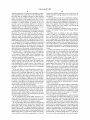
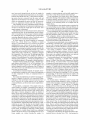
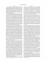
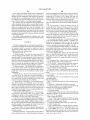
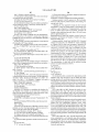
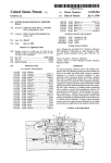
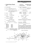
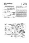
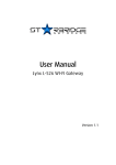
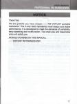
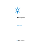
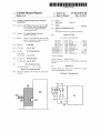
US008616072B2
(12) Ulllted States Patent
Boeke et a].
(54)
(10) Patent N0.:
(45) Date of Patent:
SYSTEM AND METHODS FOR SAMPLING
MATERIALS
(75) Inventors: Jef D. Boeke, Baltimore, MD (US); Min
(51)
Int. Cl.
G01N 1/00
(52)
TOWSOH, MD (Us); shunyou Long,
Lutherville, MD (US)
(73) Assignee: The Johns Hopkins University,
Baltimore, MD (US)
Notice:
I
(22)
73/863 11
(56)
References Cited
Subject to any disclaimer, the term of this
US- PATENT DOCUMENTS
4 293 578 A * 10/1981 Stone
U~S-C- 154(1)) by 297 days-
5,267,490 A * 12/1993 Howells ..
Appl. No.:
PCT Filed;
12/223,885
Feb 13, 2007
(87)
(65)
PCT NO"
§371 (6X1)
PCT/Us2007/004139
(2), (4) Date:
Aug. 9, 2010
11/1994
426/332
Peacock ..................... .. 43/6.5
6,444,171 B1 *
9/2002 Sakazume et al
7,022,528 B2 *
4/2006
2003/0026732 A1
73/86352
Avdeef et a1. .... ..
422/65
436/172
2/2003 Gordon et a1.
2004/0014097 A1*
1/2004
McGlennen et a1. ........... .. 435/6
2005/0188705 A1*
9/2005
Jones et a1. ..................... .. 62/86
2007/0014692 A1*
2007/0105214 Al*
1/2007 Erb et a1. ......... ..
422/82.11
5/2007 Micklash et a1. ........ .. 435/3061
* Cited by examiner
PCT Pub' N05 W02007/095366
Primary Examiner * Robert R Raevis
PCT Pub. Date: Aug. 23, 2007
(74) Attorney, Agent, or Firm * Johns Hopkins Technology
Transfer
Prior Publication Data
Us 2010/0294046 A1
Nov. 25, 2010
Related U s A
' '
(60)
.
(58) Field of Classi?cation Search
None
See application ?le for complete search history.
patent is extended or adjusted under 35
_
(86)
(2006.01)
......... .... ...... ... ................................. ..
5,361,528 A *
(21)
Dec. 31, 2013
1'
Li’ Lumen/i116’ MD (Us); Heng Zhu’
(*)
US 8,616,072 B2
lication Data
PP
(57)
ABSTRACT
Provided herein are systems and methods for storage,
retrieval and sampling of materials.
Provisional application No. 60/772,767, ?led on Feb.
13, 2006.
23 Claims, 7 Drawing Sheets
907
909
902
903 j
E
908
-904
906 -
l'
E
904
US. Patent
Dec. 31, 2013
Sheet 2 017
US 8,616,072 B2
US. Patent
Dec. 31, 2013
Sheet 3 017
US 8,616,072 B2
Moving Directions
303
1,
I/F /
// ~1
FIG. 3
FIG. 4
307
1
/30a
3 2
US. Patent
Dec. 31, 2013
Sheet 4 017
US 8,616,072 B2
601
602
603
FIG. 6
801
803
FIG. 7
FIG. 8
US. Patent
Dec. 31, 2013
7
Sheet 5 017
9((12
%
/ 91
903
98 / ~-904
//%,
FIG. 9A
907 909
I,
9:2:
g
906 -
i
Q
904
FIG. 9B
US 8,616,072 B2
US. Patent
Dec. 31, 2013
Sheet 6 0f7
US 8,616,072 B2
0E
46H.DE
US. Patent
Dec. 31, 2013
Sheet 7 017
US 8,616,072 B2
mHH.UE
US 8,616,072 B2
1
2
SYSTEM AND METHODS FOR SAMPLING
MATERIALS
In one embodiment, the system further comprises a tip
sterilizer.
In one embodiment, the system further comprises one or
more destination plates for receiving retrieved samples.
RELATED APPLICATIONS
In one embodiment, the automated freeZer is a vertical or
This application claims the bene?t of US. Provisional
Application No. 60/772,767, ?led on Feb. 13, 2006, Which is
horiZontal storage freeZer
In one embodiment, the climate controlled receiving cham
incorporated herein by reference in its entirety.
ber comprises one or more of a humidity controller, an atmo
Large biomaterial and chemical library collections require
spheric gas control mechanism or a reading device to identify
the containers as they are inserted into and retrieved from the
chamber.
In one embodiment, the transfer device comprises a
precise and selective access to a subset of material under
sterile conditions. The materials are often stored in multiWell
mechanism to transport a sample tray betWeen the dispenser
and the addressable sampler.
BACKGROUND
plates at loW temperature Where each individual sample is
In one embodiment, the system further comprises a con
stored in one of the compartments or Wells. The format of
troller in communication With one or more of the automated
multiWell plates include, for example, 96 and 384 Wells as
Well as other formats. Sample plates have an ensemble of
Wells With a registeredposition for each Well. Such ensembles
of Wells may be physically linked or in a separable rack. The
ability to access large subsets of these materials With preci
sion and Without cross-contamination and to avoid thawing is
important to maintain the integrity of samples and material
collections, Which may be of limited supply. In addition, there
freeZer, the dispenser, the transfer device or the addressable
sampler.
20
cesses orders from at least one user.
In one embodiment, the controller comprises a processor
25
for processing data relative to a sample being stored in and
retrieved from the system.
In another embodiment, the controller performs at least one
of the folloWing functions: advising a user of sample avail
30
monitoring an amount of sample Within the dispenser,
informing a supplier of sample purchased by a user and
is also a need in the art to have a system that can, Without
human intervention, access a subset of the Wells in a collec
tion of source plates, take a portion or all of a sample, and
re-array the sample into a destination plate(s) according to
need.
ability, advising of sample delivery date to the dispenser,
requesting the supplier to provide additional items to replace
items dispensed from the dispenser.
SUMMARY
The present invention provides methods to store, retrieve,
and sample a subset of froZen biological and other material
In one embodiment, the controller monitors one or more of
the freeZer, the transfer device, or the sampler.
In another embodiment, the controller receives and pro
In one embodiment, a supplier communicates With the
35
(e. g., drug and candidate drug substances) While minimiZing
dispenser via the central controller.
In one embodiment, the system further comprises a com
contamination and/or damage to surrounding samples. It fur
munication netWork for providing communication betWeen
ther describes an integrated system that alloWs e?icient man
the controller and at least one user and at least one supplier.
agement of large, complex libraries of biomaterials or other
substances.
40
In one aspect, provided herein are systems for retrieving a
subset of a stored sample, comprising an automated freeZer
comprising a dispenser, a climate controlled receiving cham
ber adjacent to the dispenser, a transfer device (plate handler)
Within the receiving chamber, and an addressable sampler
a combination thereof.
In one embodiment, the controller comprises a computer.
In one embodiment, the system further comprises a climate
45
(picking robot).
50
In another embodiment, the tip comprises a metal tip With
high thermal heat capacity, metal pin, a ceramic pin, a holloW
exchange position, and interchange a container betWeen the
dispenser and the transfer device While in a transfer exchange
position.
55
mechanism.
In one embodiment, the system further comprises a heat
sensor to monitor the temperature in the vicinity of the tip.
In one embodiment, the addressable sampler comprises
maintaining sampling tips at a sampling temperature, an
In another embodiment, the chamber comprises one or
more of a reading or Writing device.
In one embodiment, the reading device is con?gured to
addressable sample picker.
der (delid slide).
In one embodiment, the transfer device is con?gured to
deliver the container to the addressable sampler.
In another embodiment, the chamber further comprises a
transporter to transport a sample from the dispenser to the
sampler.
60
one or more of a sample locator, a rotating tip station for
In one embodiment, the sample locator comprises a bar
code reader.
In one embodiment, the system further comprises a delid
supply to dehumidify the chamber and/or cool the chamber.
In another embodiment, the dispenser is con?gured to
interchange a sample container betWeen the dispenser and the
climate controlled receiving chamber While in a chamber
pin, a core sampler for retrieving a portion of a sample
In another embodiment, the tip comprises a tip head. In
another related embodiment, the tip is disposable. In another
related embodiment, the tip comprises a volume control
system for controlling the climate of the climate controlled
chamber.
In one embodiment, the climate system comprises a dry gas
In one embodiment, the dispenser communicates With the
climate controlled receiving chamber through a port.
In one embodiment, the addressable sampler comprises a
tip.
In one embodiment, the communication netWork is
selected from the group consisting of: an intranet, an Ether
net, an Internet, a telephone netWork, a Wireless netWork and
identify the sample.
In one embodiment, the sample is contained in a sample
65
plate containing other samples.
In one embodiment, the sample plate comprises a 96 or a
364 Well sample plate.
US 8,616,072 B2
4
3
In one embodiment, the tip is sterilized betWeen retrieving
In one embodiment, the system further comprises a control
system, Wherein the control system is operatively connected
With the carousel, the interchange mechanism, and chamber
samples.
for controlling their operations.
the pin in a brush bath, dipping the pin into a series of Wash
baths, or heating the pin to a sterilization temperature.
In another embodiment, sterilization temperature com
prises from betWeen about 1210 C. to about 500° C.
In another embodiment, sterilizing comprises scrubbing
In one embodiment, the system further comprises a user
station operatively connected to the apparatus, the user sta
tion comprising a data input means for inputting data to the
processor relative to the containers.
In one embodiment, the system further comprises a desti
In one embodiment, a pin comprises one or more of a
penetrating device permitting contact With material in the
nation plate handler module adapted to transport destination
mentioned compartment, Wherein the pin is one or more of
plates to a destination.
holloW, solid, or slotted.
In one embodiment, the method further comprises moni
In one embodiment, the destination comprises one or more
of a freezer, a refrigerator, an incubator, a hood, or a climate
toring the temperature of the tip.
controlled environment.
In one embodiment, the system further comprises a plate
In another embodiment, the tip comprises a volume control
mechanism. In another embodiment, sampling comprises
replicating a sample plate.
queuing system.
In one aspect, provided herein are methods for sampling a
Other embodiments are disclosed infra.
frozen sample, comprising retrieving a sample in a container
from a freezer, transferring the sample to an addressable
sampler, and sampling the sample and transferring the sample
BRIEF DESCRIPTION OF THE DRAWINGS
20
to the freezer.
In one embodiment, the method further comprises delid
ding a sample plate in a climate controlled chamber
In one embodiment, the method further comprises deter
mining the location of the sample in the container prior to
FIG. 1 is a How chart of an exemplary system.
FIG. 2 is a schematic of an exemplary system shoWing an
automated freezer With dispenser, a transfer device (plate
25
sampling.
and reader device.
In one embodiment, retrieving the sample comprises eject
FIG. 3 depicts a side vieW of a component of one embodi
ing the container to an exterior of the freezer for transport to
an addressable sampler.
In one embodiment, sampling comprises transiently thaW
ment of a transfer device.
FIG. 4 depicts a top vieW of a component of one embodi
30
ing at least a portion of the sample.
In another embodiment, the sample rapidly refreezes upon
return to the freezer. In one embodiment, the container com
prises a multiWell plate.
In another embodiment, adjacent samples to the sample
being sampled are not thaWed.
In one embodiment, the method further comprises sealing
the container With a seal prior to freezing in the freezer a ?rst
time.
In another embodiment, the seal comprises a foil seal, a
plastic seal, a polymer seal or a septum.
35
40
In one embodiment, the method further comprises placing
a lid on the sealed container prior to freezing the sample
before and/or after sampling.
In one embodiment, the method further comprises trans
45
ferring the portion of the sample to a destination plate.
In one embodiment, the method further comprises sam
pling one or more further samples from the container.
In one embodiment, the method further comprises trans
ferring each of the one or more further samples to a destina
handler), the addressable sampler (picking robot, tip, tip
heater, temperature sensor), the controller, destination plates
ment of a transfer device.
FIG. 5 depicts a side vieW of a component of one embodi
ment of an addressable sampler.
FIG. 6 depicts a top vieW of a component of one embodi
ment of an addressable sampler.
FIG. 7 depicts a side vieW of a component of one embodi
ment of an addressable sampler component, e. g., a rotating tip
station.
FIG. 8 depicts a top vieW of a component of one embodi
ment of an addressable sampler component, e. g., a rotating tip
station.
FIG. 9A depicts a side vieW of a component of one embodi
ment of a climate controlled receiving chamber.
FIG. 9B depicts a top vieW of a component of the embodi
ment of the climate controlled receiving chamber illustrated
in FIG. 9A.
FIG. 10A shoWs yeast S. cerevisiae plates; FIG. 10B shoWs
bacterial E. coli plates; FIG. 10C shoWs “heat map” repre
sentation of bacterial groWth as detected by a 96-Well plate
50
tion plate.
In one embodiment, the freezer comprises a Biophile and
reader measuring A600. Blue represents background read
ings and shades of red represent different extents of groWth.
FIG. 11A depicts yeast S. cerevisiae plates; and FIG. 11B
shoWs bacterial E. coli plates.
or a Biobank.
In another embodiment, sampling comprises loWering a
heatedpin through the seal of the container and into the frozen
sample, Wherein at least a portion of the sample is thaWed.
DETAILED DESCRIPTION
55
The presented herein is an automated storage and retrieval
In another embodiment, sampling comprises loWering a
apparatus, and related method thereof, providing a sample
process management system to the store and retrieve samples.
Samples in containers are stored and retrieved automatically
coring pin or coring saW through the seal of the container and
removes a portion of the frozen sample.
In one embodiment, the method further comprises steriliz
60
ing the pin betWeen sampling.
(access means)) that is automatically dehumidi?ed by a dry
In another embodiment, the pin is disposable.
In another embodiment, the pin comprises a temperature of
betWeen about 30 and 70° C.
In one embodiment, once partial or full thaWing occurs, the
pin is removed from the source Well and dipped into the
destination Well, releasing a sample of cells.
through a dispenser (e. g., an airlock climate-control chamber
gas purge (e.g., carbon dioxide or nitrogen purge or the like).
This purge rapidly reduces ambient humidity to a desirable
relative humidity (RH), (e.g., less than about 15% RH), to
65
minimize or eliminate the accumulation of frost on the
sample plates. Microplates or storage containers, or the like,
are identi?ed, for example, using barcode technology or radio
US 8,6l6,072 B2
5
6
frequency technology. The containers containing the samples
compartment operably linked one or more of the freeZer, the
are transferred by the transfer device to the addressable sam
climate controlled receiving chamber, the transfer device or
pler Where they are sampled using pins or other described
the sampler.
means. The sample containers or plates are then transferred
In one embodiment, methods for automatically sampling a
back to the freeZer via the transport device (e.g., a rotary
stored sample from a froZen sample plate comprises provid
mechani sm) through the dispenser. The freeZer transports the
ing a carousel in the freeZer compartment; depositing a con
tainer into a climate-controlled chamber; controlling the cli
mate of the chamber While the container remains in the
chamber; sampling one or more samples, and returning the
containers to a derived location for example by use of a
carousel to one of the stationary addresses. For illustrative
purposes only, the carousel and stationary nests may have a
combined capacity of 1,000 standard microplates. It is con
container to the freeZer carousel.
templated that various capacities may be designed.
In certain embodiments, exemplary freeZers include, for
example, the Biophile (TekCel) and the Biobank (Therrno
An advantage of the present invention operation in a stand
Systems).
alone mode or can be integrated into a completely automated
laboratory. The systems are scalable to meet the needs of
small laboratories as Well as large institutions that require
Described herein are methods to store and ef?ciently
retrieve a subset (e.g., user-de?ned) of biological materials
(e.g., viruses, bacteria, yeast, fungi, sperm, Worms, mamma
lian cells, plant tissue, animal tissue) from a freeZer (e.g.,
long-term storage of large numbers of samples. Another
advantage of the present invention is that the apparatus can be
designed as a slide-in unit for existing ultra-cold freeZers,
Which Will keep the majority of the hardWare in the door so as
to be insulated from the freeZer compartment, minimizing
both the number of loW-temperature hardWare components
and the actual alteration to the freeZer itself. HoWever, the
freeZer, as described herein, may be altered to accommodate
additional features of the systems. A reduced number of mov
ing components continuously exposed to the design tempera
source compartment). The methods and systems described
herein reduce contamination of the sample and mistakes in
20
a destination compartment or plate for further processing or
storage.
25
ture of about —800 C., Which reduces the cost of production.
Further advantages of the present invention are attributed
to the improved sample quality, loWered operating costs,
accuracy of clone picking and reduced maintenance of the
automated storage and retrieval apparatus.
In one embodiment, the dispenser comprises at least one
rotatable carousel located in the freezer, the carousel com
prising at least one cell de?ned by tWo side Walls each side
Wall extending from a central location of the carousel, an
access hatch aligned With the or each carousel for accessing
sampling biological samples While increasing ef?ciency. Por
tions of the samples (e.g., the inoculum, dispensed biomate
rial, sampled material, portion of sample) may be placed into
30
In certain embodiments, the dispensed biomaterial to be
managed or retrieved is, for example, placed in a sample plate
(e.g., single Well, 2 Well, 3 Well, 6 Well, 16 Well, 96 Well, 384
Well plate, 1536 Well plates) sealed With a foil (e.g., alumi
num, gold, tin, etc.) or polymer (plastic, rubber, etc.) seal and
covered by a plastic lid prior to the storage. This lid is
removed to alloW access by the addressable sampler (e.g.,
picking robot). Retrieval of a collection of materials in pre
sealed plates (e.g., source compartments) is performed by a
penetrating pin from the top of the 96 or 384 or l526-Well
35
plate at a given Well position. The pin of the addressable
an interior of the at least one cell; and a motor for rotating the
sampler may contain a slot or other recess to facilitate uptake
carousel.
In one embodiment, the controller performs at least one of
of a small sub-sample of liquid from the Well. The position
may be registered manually or, for example, by robotics con
trolled by a computer. The penetration of the pin through the
foil seal permits contact betWeen the tip of pin and the com
partmented material, either in solid (froZen) or liquid form.
the folloWing functions, rotation of the carousel by control
ling the motor, controlling dispensing of an item from the
40
dispenser, monitoring an amount of an item Within the dis
penser, reporting to the central controller the amount of an
item Within the dispenser, making an activity log and tem
perature log of the dispenser, informing a user of availability
of an item, receiving information from the central controller
in relation to item delivery to the dispenser and temperature
control setting of the dispenser and monitoring and control
ling an internal environment of the dispenser.
In one embodiment, the controller comprises a computer.
More than one controller may be associated With the system
and may control discrete functions. All or any subset of func
tions may be controlled by one controller. In some embodi
ments, the control system comprises a processor for process
ing data relating to contents of the containers being stored in
and retrieved from the apparatus.
Methods for thaWing a froZen sample are described herein.
The retrieval of the pin and sample contained therein or
45
a speci?ed or random Well of a “destination plate”) to transfer
sample on or in the pin.
50
arm system that loWers a precision-heated (temperature-con
60
plates While a plate is being sampled. The queuing of the
ture Warm enough to melt a portion of or the entire block of
material in that compartment but not Warm enough to harm
the materials (in certain embodiment, or affect neighboring
sample in the sample plate). The temperature or temperature
range for a particular sample is easily determined empirically
sample plates Will alloW for higher throughput of retrieving
samples. The queuing of sample plates may be just afterbeing
system may also be in the freeZer compartment or in a freeZer
The methods are accomplished by the systems described
herein, for example, by an addressable sampler (e. g., a robotic
trolled) pin through the seal of a sample and into the froZen
sample block. The pin is heated to a predetermined tempera
system alloWing the freeZer to unload one or more additional
dispensed from the freeZer, before or after being delidded (for
lidded sample plates), or in-line for the sampler. The queuing
In one embodiment, the methods comprise WithdraWing a
small sample (liquid or solid) from a Well containing a froZen
biomaterial, (e.g., stored at or around —800 C.). The sample is
WithdraWn under sterile conditions, in a short period of time
(shorter than user manual selection of a sample from a sample
plate), and transfer a portion of the sample to a destination
Well (e.g., containing groWth medium).
55
In one embodiment, the system further comprises a user
station operatively connected to the system, the user station
comprising a data input means for inputting data to the pro
cessor relative to the samples or the sample containers.
In one embodiment, the system comprises a plate queuing
thereon comprises the retrieved sample. The pin may then be
inserted into a bio-compatible sample compartment (e. g., into
65
by one of skill in the art. The pin, for example, rests in a
thermostatically controlled heating block or a rotating tip
station, that can be Warmed precisely to the desired tempera
US 8,616,072 B2
7
8
ture; heat travels through the pin and into the sample by
conduction. Exemplary pin tip temperatures are, for example,
example, a rotating coring tip could cut/drill sample from a
tissue slice or other frozen material Without thaWing it.
In one embodiment, the system alloWs object sampling
betWeen about 30 and about 70° C. Once partial or full thaW
ing occurs, the pin is removed from the source Well and
folloWed by freezing of the samples by adding visual devices
to identify randomly positioned objects. For example, this
dipped into the destination Well, releasing a sample of cells
Would alloW microbial colonies groWn on an agar plate (and
Which can subsequently be groWn and used for many pur
randomly or non-randomly placed) to be samples and the
poses, e.g., preparation of nucleic acid, PCR, bioassays etc.
After sampling, the source compartment rapidly refreezes
samples frozen.
In one embodiment, a plate handler replaces used plate lids
to avoid ice buildup on source plates, Which is problematic. In
one embodiment, the lids are coded to be read by the reading
device. In other embodiments the sample plates are coded.
In one embodiment, the system further comprises a desti
due to the loW temperature of biomaterials in adjoining Wells
and also by returning the sample plate to the freezer. Thus
sample integrity is maintained.
After delivering the inoculum, the pin may be cleaned and
sterilized before reuse. In one embodiment, the pin is dispos
able. For reusable pins, there are many Well-knoWn methods
nation plate handler. The destination plate handler may delid
and relid destination plates and transfer them to a “plate
hotel”, refrigerator, freezer or other incubation station.
In one embodiment, loW pro?le 96-Well (Genetix X 6011)
or 384-Well (Genetix X7001) plates With or Without samples
for sterilizing the pin, e.g., scrubbing the pins in a brush bath,
sonicating, dipping the pin into a series of Wash baths, and/or
heating the pin to an extremely high temperature.
In certain aspects, the system comprises an automated
freezer (e.g., robotic freezer (e.g., Biophile)), a transfer
device (e.g., plate transfer robot (e. g., TWister 2)), an optional
are stored in the freezer With the plastic lid on.
20
delidding device (e. g. robotic arm to remove the lid, e.g.,
modi?ed from motorized slide), a climate controlled receiv
ing chamber containing the transfer device and optionally the
delidding device, and an addressable sampler (e.g., robotic
25
arm or gantry system modi?ed to hold heated pin device (eg
Adept Cobra)), and a controller (e.g., computer to integrate
the components of the system (e.g., the heating/temperature
controlling system, provide a user interface to operate the
system). In one embodiment, the system further comprises a
destinationplate module (e.g., a robotic arm and plate hotel to
the system is also adapted to replicate plates (e.g., replicate
from 384-Well to 384-Well With 200 nl pin tool).
30
In certain embodiments, the system includes, for example,
the folloWing components: 1) Biophile BSU automatic
freezer; 2) Adept Cobra s600 robot (component of the plate
transfer device); 3) Zymark TWister II for plate handling
(component of the plate transfer device); 4) Animatics Smart
35
motor 1 for rotating tip station (component of the addressable
move destination plates to, for example, a heated incubator).
Exemplary freezers include for example, a Biophile auto
matic freezer, Which holds 931 96- or 384-Well plates. The
Biophile can therefore organize up to 357,504 samples. The
The system, in one embodiment, stores samples (e.g., plas
mid libraries in bacterial cells, yeast knockout collections,
etc.) in a —80 C automatic freezer (BSU; BioPhile), loads and
unloads plates to and from the freezer, and picks individual
isolates from frozen (source) plates to destination plates.
The system is adapted to transfer samples from, for
example, individual sample containers, 96-Well to 384-Well
or 384-Well to 96-Well format With 96-pin (Genetix X5054),
sampler); 5) Yamaha slide for plate transfer and delidding
(additional optional component of the plate transfer device if
freezer is adapted to retrieve or return any of the 931 plates in
about 30 seconds. In one embodiment, the system comprises
more than one source freezer.
the plate has a lid); 6) Animatics Smart motor 2 for plate
As used herein, biomaterial includes, for example, micro
bial prokaryotes or eukaryotes, cells, viruses, the components
transfer (component of the plate transfer device); 7) IBM PC
40
(referred to as the central or controlling PC); 8) Cisco router
of cells, components of viruses, or component tissues or
for netWorking; 9) Advantech temperature test module; 10)
organisms.
HAKKO 852 hot air gun (component of the addressable
sampler); 11) Custom control console.
The systems described herein are useful for managing col
lections of bacteria (Escherichia coli), retroviruses, bacte
riophages or other recombinant viruses and yeast (Saccharo
myces cerevisiae) for various purposes, and of chemical
45
System softWare package integrates a variety of commercial
compound libraries, and frozen tissue micro-samples/homo
genates.
As used herein, a component of the sampler is the pin,
Which includes, for example, a penetrating device that per
control softWare packages associated With off the shelf com
ponents, for example, 1) system softWare; 2) Biophile
50
mits contact With material in the mentioned compartment
With biomaterials; pins can be holloW, solid, slotted or have
other types of recesses designed to adhere to droplets of
liquid. The tips may be heated passively (hot air, heat block)
or actively (by conduction). The temperature of the tip may be
monitored by a real-time temperature monitoring system by
incorporating a thermostat, alloWing more precise tempera
55
module. The tip may also be a core sampling device to core a
frozen samples, e.g., Without thaWing the sample. For
GenOne softWare Which runs on the ?at panel PC on the
BioPhile freezer. User can operate the freezer through a touch
screen When the System softWare package is not activated.
There are 2 channels connecting the panel PC to the central
PC. One is TCP/IP used for database management. Another is
an RS -232 interface alloWing the System SoftWare package to
send commands for loading/unloading plates to/ from the Bio
Phile; and/or 3) Adept robot softWare Which is executed by
the SmartController. It communicates With PC through TCP/
IP netWorking; 4) TWo pieces of SoftWare for the Animatics
ture control. A thermistor may also be imbedded in the tip to
provide real -time monitoring on intra-tip temperature. In cer
tain embodiments, sterilized disposable arrayed tips or indi
vidual tips are used. The tips may also have liquid volume
control mechanisms (e.g., pipetting). For example, constant
volumes of frozen samples could be picked up and delivered
by the system, for example by employing a holloW picking
pin, connected to a liquid volume control (e. g., pipetting)
SoftWare
The System adopts a “distribution control” concept. The
Smart motors. They are doWnloaded to the motors. They
60
connect to the Adept robot through SmartController RS-232
ports. There is no direct control from the System softWare
package to the smart motors and/or 5) Hit list preprocessing
softWare. This is another piece of custom softWare currently
65
plate order sheet and generates the hit list for robot.
Turning noW to the draWings, the present invention is sche
matically shoWn in the plan vieW of FIG. 1 and perspective
consisting of a Microsoft Excel macro Which loads the tem
US 8,616,072 B2
10
insertion and retrieval. The receiving chamber 902 encom
passes the dispenser 904 to alloW communication betWeen
freeZer 901 and receiving chamber 902, and an exterior door
903 to alloW communication betWeen the exterior environ
vieW of FIG. 2, Which includes an automated storage and
retrieval apparatus having one or more storage carousels 20
disposed in an automated freezer 2, With one or more optional
stationary racks, a climate controlled receiving chamber (13,
ment (or adjacent area) and chamber 901. The chamber 901
N2 environmental chamber), a transfer device 4. The climate
controlled receiving chamber 13 is generally disposed on a
Wall 11 of the freezer 2. A control system 1 is coupled to the
has a climate control system 908 that provides an air purging
capability to dehumidify and optionally cool the air in the
chamber 902 before dispenser 904 is opened. A scanning
reader device 935, preferably a barcode reader, is situated in
reading device 18 (e.g., barcode scanner), the addressable
sampler (components 5, 6, 8, 9, 16), transport device 4, and
climate controlled chamber 13 for controlling their opera
the chamber 902 to identify storage containers as they are
inserted into and retrieved from chamber 902. Information
relative to the storage containers is transmitted from reader
device to central and/or remote processor.
Referring to FIG. 9B the storage containers 909 are carried
tions. Generally, the control system 1 controls the operation
of the apparatus so that the containers 14 can be loaded from
the exterior or sampling position into the climate-controlled
chamber 13 for retrieval by the transport device 4 and the
plate handler 3 to dispensing port 21 for insertion onto the
carousel 20 in the freeZer 2. Stored containers subsequently
can be retrieved from the carousel 20 the plate handler 3 and
by the transport device 4 and available to be taken to the
sampler (components 5, 6, 8, 9, 16).
FIG. 3 shoWs a side vieW of a component of one embodi
20
ment of a transfer device. A sample container (plate) is dis
pensed from the freeZer through the dispenser (shoWn as 21 in
FIG. 2) and in one embodiment taken by a robotic arm to the
transport mechanism 4. The transport mechanism comprises
a slide 301 a reading device 305, a guide Wheel 306 to prop
erly locate the plate, a cover 308 With a tip access slot 307, and
a motor to drive the operations. The transport device is con
25
dioxide, or the like), that rapidly reduces ambient humidity to
any desired level, e.g., less than about 25% relative humidity
(RH) and as loW as about 1% RH. In fact, any compressed gas
from Which moisture has been removed Will reduce the
humidity in the airlock, and Will cool the airlock by adiabatic
30
expansion to about —100 C. to about 00 C., or as desired.
Preferred embodiments of the present invention, an auto
trolled by the controller. In certain embodiments, the robotic
transport arm may be a conveyer belt operably coupled to the
dispenser and the transport device may be integral. The trans
port device may be located Within or outside of the climate
mated storage and retrieval apparatus, and related method
controlled receiving chamber. The receiving chamber sur
rounds the dispenser of the freeZer.
In regard to FIG. 4, depicted is a top vieW of a component
of one embodiment of a transfer device as shoWn in FIG. 3. 35
The sample plate 404, is shoWn on the slide 401, and is
transported to the tip access slot 407 by the controller so that
the proper sample in the plate may be accessed by the addres
sable sampler. The addressable sampler has access to the
sample through the tip access slot 407.
40
assembly. In this embodiment, the tip is passively heated by a
ultra loW freeZer-set point of the apparatus can be backed up
hot air gun and no heating assembly is included. In some
45
One skilled in the art Would appreciate that various types
50
With regards to control operations, the present invention
automation and robotic motions described herein are pro
vided in part by the control system and processor. It should be
noted that the folloWing exemplary sequences of operations
may be varied, partially omitted, overlapped to reduce the
noZZle 702. The tips are rotated every 1 s to 2 minutes,
55
FIG. 8 depicts anther top vieW of a component of one
embodiment of an addressable sampler, e.g., a rotating tip
total elapsed time of operation, or reordered in an alternative
sequence.
Operation for depositing a storage sample tray is provided
station, the tip rack 801 With four positions for tips 803.
It is envisioned that a control system and computer system
can be accessed directly by using the touch screen interface
and/ or remotely by a stand-alone personal computer or With a
local area netWork (LAN).
Next, details of the climate controlled receiving chamber
Will be provided, as best shoWn in FIGS. 9A and 9B. A
particularly desirable feature is that the climate-controlled
chamber 902 prevents ambient, humid air from entering the
interior of freeZer compartment 901 during storage container
by installing a cylinder of liquid carbon dioxide.
and substitutes for interior and exterior chamber doors can be
used. Moreover, a single door can be utiliZed Which can
rotated betWeen interior and exterior sides.
FIG. 6 depicts a top vieW of a component of one embodiment
depending on the temperature desired for sampling.
or greater. The normal design operating temperature of the
freeZer compartment of the present invention is about —80° C.
It should be noted that the present invention is contemplated
to operate at conditions colder than ultra loW temperatures in
the range of about —1400 C. to about —90° C. Conveniently, if
uled outageithen liquid carbon dioxide can be pumped into
the system and keep it at approximately —78° C. Thus, the
ment of an addressable sampler, the tip 505 and related
of an addressable sampler, adapter 601 With four spring com
pensators 602. FIG. 7 depicts a side vieW of a component of
one embodiment of an addressable sampler, e.g., a rotating tip
rack 704 and the heater 702. The tip rack 704 is rotated by a
motor 701 so that each tip is exposed to hot air from the hot air
thereof, operate at an ultra loW temperature from about —50°
C. to about —90° C. It should be understood that the apparatus
may operate in a range of —50° C. up to ambient temperature
the freeZer fails for Whatever reasonimaintenance or sched
FIG. 5 depicts a side vieW of a component of one embodi
embodiments, a heating assembly is included in the tip
assembly. The tip assembly as shoWn comprises a magnetic
tip holder 503, a spring compensator 502, and an adapter 501.
by a transfer device 907 to the addressable sampler (picking
robot). The transfer device 907 can transport the container
909 to the exterior as the exterior door is open. Alternatively,
the transfer device 907 can transport the container 909 to the
interior of the freeZer through the dispenser. A climate control
system 908 is in communication With the receiving chamber
902 that dehumidi?es and optionally cools the chamber 902
While the container is isolated therein, e.g., both exterior and
interior doors are closed. The climate control system 908
includes a dry gas or dry air purge (e.g., nitrogen, carbon
as described beloW. In a ?rst step, the dispenser of the freeZer
60
opens and the sample tray exits into the climate controlled
chamber. The lid of the tray is removed and the transfer device
transports the tray to the addressable sampler through the
exterior door of the climate controlled chamber. Once
sampled, the transfer device transports the tray back to the
dispenser for placement back in the freeZer. The reading
65
device of the system may be located in the climate controlled
receiving chamber or associated With the addressable sampler
or both.
US 8,616,072 B2
11
12
In one embodiment, a central controller locates relevant
thereof and may be implemented in one or more computer
storage container information in the database and location of
systems or other processing systems, such as personal digit
assistants (PDAs). In an example embodiment, the invention
storage container in the freezer (or stationary storage racks) is
determined. Optionally, if security is required, then an access
code is entered via data input device such a display panel
integral With the apparatus housing or a remote processor, and
Was implemented in softWare running on a general purpose
computer. Computer system includes one or more processors
in a communication infrastructure (e.g., a communications
bus, cross-over bar, or network). Computer system includes a
con?rmed by central processor 81 to alloW access to the
desired storage container. The container is ejected from the
display interface that forWards graphics, text, and other data
freezer through the dispenser.
from the communication infrastructure (or from a frame
It should be noted that the motors for the freeZer, transfer
device, the addressable sampler and can be a variety of types
of motors knoWn to those skilled in the art, including but not
buffer not shoWn) for display on the display unit.
The computer system may also include a main memory,
preferably random access memory (RAM), and may also
include a secondary memory. The secondary memory may
include, for example, a hard disk drive and/or a removable
limited thereto servo motors and stepper motors, or any direct
current (DC) motor With suitable position or velocity control
lers. In the various preferred embodiments disclosed herein,
storage drive, representing a ?oppy disk drive, a magnetic
tape drive, an optical disk drive, etc. The removable storage
the motors are mounted outside of the freeZer to extend the
life of the component and improve the overall serviceability
drive reads from and/or Writes to a removable storage unit in
a Well knoWn manner. Removable storage unit, represents a
of the apparatus. In one embodiment, the servomotors may be
of a SMART MOTOR by Animatics, Corp. These types of
servo motors are microprocessor controlled, ensuring accu
20
?oppy disk, magnetic tape, optical disk, etc., Which is read by
and Written to by removable storage drive. As Will be appre
ciated, the removable storage unit includes a computer usable
rate placement and monitoring of the robotics operating
Within the critical environment; hoWever, any position or
velocity controlled motors may be used. Motors are mounted
storage medium having stored therein computer softWare
near the particular component they are controlling.
The general features of the present invention control sys
and/or data.
The computer system may also include a communications
interface. Communications interface alloWs softWare and
data to be transferred betWeen computer system and external
devices. Examples of communications interface may include
25
tem Will be discussed, as shoWn in the block diagram of FIG.
1. The control system interfaces With a computer system that
may be integral With the housing or remote via a Wire or
Wireless communication, or any combination thereof. More
over, the control system may be in communication With and
a modem, a netWork interface (such as an Ethernet card), a
30
integrated With a laboratory information management system
(LIMS). The control system is operatively connected With the
various motors, actuators, position sensors, and identi?cation
sensors. It is contemplated that that the information derived
from the sample or Work pieces carried in the containers While
practicing the present invention Will provide an information
technology platform for the user. The computer system is
intended to be a user-friendly, utiliZing WindoWs-based plat
form or any other operating system, and may be integrated
With a variety of laboratory information management sys
tems. It is envisioned that the control system and computer
system can be accessed directly by using a touch screen
interface or remotely by a stand-alone personal computer or
form of signals, Which may be electronic, electromagnetic,
optical or other signals capable of being received by commu
nications interface. Signals are provided to communications
35
(or any other communication means or channel disclosed
40
ucts are means for providing softWare to computer system.
45
Computer programs (also called computer control logic)
puter programs may also be received via communications
interface. Such computer programs, When executed, enable
50
computer system to perform the features of the present inven
tion as discussed herein. In particular, the computer pro
grams, When executed, enable processor to perform the func
tions of the present invention. Accordingly, such computer
programs represent controllers of computer system.
55
In an embodiment Where the invention is implemented
using softWare, the softWare may be stored in a computer
program product and loaded into computer system using
movement of loW demand samples into longer-term storage
unitsimaximiZing the e?iciency of the user’s sample pro
removable storage drive, hard drive or communications inter
face. The control logic (softWare), When executed by the
cess management system. Furthermore, the present invention
60
processor, causes the processor to perform the functions of
the invention as described herein.
In another embodiment, the invention is implemented pri
marily in hardWare using, for example, hardWare components
such as application speci?c integrated circuits (ASICs).
ogy by receiving excellent sample security, optimal sample
visibility, optimal quality assurance, sample migration con
trol and ?exible data management.
The controls and processing of present invention may be
implemented using hardWare, softWare or a combination
The invention includes such computer program products.
are stored in main memory and/ or secondary memory. Com
ture, employing sample usage frequencies, prompts the
apparatus enables the user to generate a variety of reports in
support of the user’s quality assurance needs. Finally, the user
Will bene?t from the present invention’ s information technol
link and other communications channels.
In this document, the terms “computer program medium”
and “computer usable medium” are used to generally refer to
media such as removable storage drive, a hard disk installed in
hard disk drive, and signals. These computer program prod
parameters to control container (sample) access based on
research groups, research campaigns or individual laborato
ries. For instance, sample data can be con?gured by the user
to meet the user’ s particular research requirements. The data
base can then search the user’s sample populations to ?nd all
the samples that match the user’s requested research param
eters. Moreover, time/temperature pro?les and sample access
histories are maintained continuously. The present invention
alloWs the user to set sample migration thresholds. This fea
interface via a communications path (i.e., channel).A channel
herein) carries signals and may be implemented using Wire or
cable, ?ber optics, a phone line, a cellular phone link, an RF
With a local area netWork (LAN).
The present invention apparatus provides the user the capa
bility, among other things, to set top-level user-de?nable
communications port, a PCMCIA slot and card, etc. Software
and data transferred via communications interface are in the
65
Implementation of the hardWare state machine to perform the
functions described herein Will be apparent to persons skilled
in the relevant art(s).
US 8,616,072 B2
14
13
process by being positioned above the hot air gun. Positions 2,
In yet another embodiment, the invention is implemented
using a combination of both hardware and softWare. In an
3 and 4 are ambient air cooling stations; position 4 is the
example software embodiment of the invention, the methods
pickup station. The motor is on a constant dWell time, cur
described above Were implemented in VISUAL BASIC con
rently calibrated at 20 seconds. This dWell time can be cali
trol language, but could be implemented in other programs
such as, but not limited to, C++ programming language.
The invention may be embodied in other speci?c forms
Without departing from the spirit or essential characteristics
brated to adjust average tip temperature if necessary.
9. TipsiThese are metal tips With high thermal capacity.
They are spring loaded to ensure reliable release from the tip
head.
10. Tip Heat SensoriThis device monitors the hot air
thereof. The foregoing embodiments are therefore to be con
temperature in the vicinity of the pin at position 1 of the tip
sidered in all respects illustrative rather than limiting of the
invention described herein. Scope of the invention is this
indicated by the appended claims rather than by the foregoing
station. This alloWs the system to determine if the pin has
Warmed to the correct temperature to automatically transition
description, and all changes Which come Within the meaning
the system from standby/Warmup phase to picking phase.
and range of equivalency of the claims are therefore intended
to be embraced herein.
solvents for sterilization. The robot dips the used tip in the
The patents, patent applications, references and other
Well(s) prior to heat sterilization. This Was found to give more
reliable sterilization than heat alone.
11. Ethanol WelliTWo Wells hold 70% ethanol or other
documents identi?ed herein are incorporated in their entirety
12. N2 Control Valve/lid dryeriIt controls dry N2 injection
herein by reference.
to the Environmental Transfer chamber to minimize con
EXAMPLES
20
It should be appreciated that the invention should not be
construed to be limited to the examples noW described; rather,
the invention should be construed to include any and all
applications provided herein and all equivalent variations
13. N2 Environmental Transfer ChamberiIt encloses the
plate handler, delid slide, and barcode reader. It interfaces
25
14. Frozen Sample PlateiThis is the multi-Well source
In reference to FIG. 2:
30
delid the source plate by coordinating With the delid slide, 3)
15. Destination PlateiThere are one or more plates to
robot, 4) controls dry nitrogen gas supply and 5) performs
35
16. Hot Air GuniIt heats up the tip to sterilize and/ or dry
the tip. Currently temperatures of 200-3500 C. are used.
17. NetWork RouteriIt links the major devices in the
system for reliable and quick operation.
18. Barcode ScanneriIt reads the barcode for each plate.
This information is used for ID validation When retrieving the
accepts retrieves and returns source plates through a robotic
airtight port. It also has its oWn database for plate number
management.
plate. It is typically sealed With foil and covered by a loose
?tting plate lid, and is labeled With a unique barcode for
identi?cation tracking. The sample information is stored in a
database.
accept the sample(s) delivered by picking robot.
sends the source and destination positions to the picking
other detections and human machine interface operation.
2. Automatic FreezeriThe BioPhile BSU stores the plates
in the carousel inside, Which is protected by dry N2 gas. It
With the port of the robotic freezer. It can also be extended to
interface With multiple freezers.
Within the skill of the ordinary artisan.
1. Central computeriThis hosts the system main control
softWare package and the database. The control softWare 1)
reads the sample list, sends command to robotic freezer to get
the correct plate, 2) controls the plate handler to deliver and
sumption of protective dry, sterile N2 gas. The N2 gas is
directed at the underside of the lid holder that holds the
current source plate lid, reducing ice buildup on the lid.
40
3. Transfer deviceiThe TWister II can retrieve a plate With
plates.
19. CarouseliIt sits inside the freezer and serves as the
hotel for plates.
or Without lid on. Its robotic arm can deliver the plate to
various programmable positions. Its gripper is programmed
20. Dispensing PortiIt is an air tight port Which receives
for various forces to perform different actions such as lid
removal When the lid sticks due to ice buildup.
4. Transfer deviceiDelid SlideiIt moves along one axis.
This alloWs the plate to be delidded, to have its barcode
scanned, to be repositioned if necessary and to be located at
positions corresponding to the desired column of a multiWell
plate so that it is exposed to the access slot alloWing the robot
to pick the desired sample. This is a commercial slider modi
?ed With a custom delidding frame.
and releases plate.
Operation Procedure:
Step 1: Check the folloWing issues before starting System
45
50
5. Addressable sampler (picking Robot)iThis is an indus
trial precision robot (Adept Cobra). It can access a Wide
Working space rapidly. It can be equipped With different func
55
tional heads. It can also Work With a visual system.
6. Tip HeadiThis is designed for reliable tip handling. It
has spring compensation for different plate types to compen
sate for variable sample height in different sample Wells. It
also provides a gentle and constant doWnWards force as the tip
60
65
3; 1; JH B 8000; 384; 1; 1; 3”i[Gene ID; Source Plate
Barcode; Plate format (96/384); RoW; Column; Destination
plate; Plate format (96/384); Plate position (1-4); RoW; Col
constant temperature control for the tip as Well.
7. Robot ControlleriThis is the controller dedicated to the
picking robot. It provides digital control for other detection
8. Rotating Tip StationiIt has 4 positions for tips. When it
rotates, the tip at position #1 Will go through the sterilization
4) Cover the chamber.
5) Turn Nitrogen manual valve on. Check the Biophile With
“Biophile CommTestl” on the desktop if necessary. Perform
“AAA”, “H”, “R” in sequence.
Step 2: Prepare the “hit list”
1) Go to E:\Order and open Genlist.xls With Macro enable.
2) Click “Load Order” to input the hit list in Excel ?le
Which is in the proper template format.
3) Chose the destination plate format: 96 or 384-Well.
4) Click “Generate List”
5) Copy column M, paste to ConTEXT and save as text ?le.
6) Notice the format ofthe list: “IOH 10003; UHA 87; 96;
thaWs the sample. It has a magnetic tip holder that provides
and valve controls.
softWare.
1) PoWer off “TRANSPORT POWER” if necessary.
2) Open the chamber cover; check the plate holder on the
transport rail With the spacer for ZERO position.
3) PoWer on “TRANSPORT POWER”.
umn]. The 1st line is the title.
US 8,616,072 B2
15
16
Step 3: Prepare Working conditions
8) If any plate location is damaged, change the database to
1) Clean up the Working surface. Move aWay any extrane
mark location as unavailable.
ous materials from the Work table.
Estimation of Volume Transferred Per Picking Operation
Starting material: LB+10% glycerol in 384 Well plate.
Plate type: 384-Well loW pro?le (Genetix) Total starting vol
2) Replace the fresh 70% ethanol in the 6-Well plate.
3) Turn Hot Air Gun poWer on.
4) Check that all four tips are in good condition and in place
on the rotating tip station. If necessary, steriliZe tips ?rst.
5) Turn on the N2 valve.
Step 4: Start Adept robot
ume per Well: 50 ML.
A picking pin Was inserted by hand into the Well and
transferred to a piece of blotting paper. Liquid transfer Was
visible as a spot of liquid for 51 sequential picks. After this
point, no further liquid could be transferred. Therefore the
1) Turn the “ROBOT POWER” on if necessary.
2) Run “AdeptWindoWsPC” from Start.
3) IP address 172.16.180.108
4) Note: if the Adept is POWER OFF, the AdeptWindoW
average volume transferred per pick from a 384 Well source
plate is approximately 1 ML.
Reproducibility of Viable Cell Transfers, Lack of Cross Con
tamination, and Estimate of Number of Viable Cells Trans
ferred on Picking Tip.
Starting materials, loaded into BioPhile BSU: Saturated
cultures of Escherichia coli “DH10B-T1” strain containing
an Ultimate ORF® clone from lnvitrogen Corporation (in
sPC software has to be started 5 seconds later right after
POWER ON. It is not necessary to turn off ROBOT POWER
for daily operation.
5) DDT prompt “Load from local disk (D) or netWork disk
(X) [default is D] 7” Select default.
6) Release any emergency button on the control pendant.
7) Press “COMP/PWR” and White button to poWer on
robot.
20
8) Type “Calibrate” and con?rm With “Y”.
9) Load program for Adept from networking disk in PC
“load nfs>xc:\ice\mainpicking.v2”
10) If program exists, either keep it or clean it With “Zero”+
25
“Y”
11) Turn the tip heater ON.
12) Run “ex mainpicking”
13) Check that the proper number and type of destination
plates, ?lled With appropriate media formulation, are in place.
30
Step 5: Start PC SoftWare
1) Click SystemNet on desktop.
2) “Reset System”iReset devices Which includes Bio
phile, TWister ll
3) “Load List”iLoad the text ?le generated in step 2.
35
4) “Start Picking”
5) Tip Temperature >45 C, (This is the average temperature
LB+50 micGm/ml kanamycin+10% [W/v] glycerol) and Sac
charomyces cerevisiae strain 4741 ho::kanMX (in YPD
medium+200 micGm/ml G418+10% [W/v] glycerol). These
cultures Were groWn in 96 Well plate Wells (loW-pro?le
Genetix plates) in 150 ML to saturation at 30° C. The cultures
Were each diluted 10-fold, 100-fold and 1000-fold into the
appropriate medium as de?ned above. These source plates
Were covered With sterile foil seals, as Well as the plastic lid,
and then froZen at —80° C. by placing them in the BioPhile.
The concentration of viable cells in the undiluted starting
cultures Was approximately as folloWs.
S. cerevisiae
108 cells per mL
or 105 cells per uL
E. coli
109 cells per mL
or 106 cells per ML
in the picking tip area above the heat gun. The tip temperature
The destination plates contained the appropriate groWth
should be >150 C. The heat gun should be set to 250° C. for
medium. They Were left open to the air during the entire
yeast. Use 300° C. for bacteria.). Program Will pause
sequence until proper temperature is reached.
40
picking operation. No special procedures Were used to mini
miZe airborne contamination. For example, the room air Was
not HEPA ?ltered, and the lcePick area Was not steriliZed With
Step 6: Finish day’s operation
1) Turn N2 valve off to conserve gas.
a germicidal lamps betWeen picking runs. These simple pro
2) Clean the table.
cedures are predicted to further minimiZe airborne contami
nation.
FIGS. 10A, 10B, and 10C illustrate the results of cross
contamination tests done With yeast and bacterial cells.
Database Manipulation
45
Sometime, it is necessary to manipulate the database for
the Biophile. For example, in case you have to unload all
plates from the freeZer manually to defrost the freeZer. Only
authoriZed people can perform these functions.
1) Go My NetWork Places.
Source plates With undiluted Wells only and prepared as
described Were used. Destination plate Wells Were inoculated
50
2) BIOPHILE on Biophile, user name “Administrator”, No
PassWord
in a pattern spelling the WordYES. As canbe readily seen only
these Wells greW.
FIG. 1A and 11B illustrate the results of the transfer experi
3) \Genone\Database\b?FreeZerData, type the passWord.
ment. Experiments are organiZed as folloWs: WellsA1-A4 are
Maintenance
Part 1: BioPhile
Every time you open the door of BioPhile, you have a lot of
problems to solve. One big headache is that you may not be
able to home the robots inside the BioPhile.
picked from four independent undiluted source Wells,
1) Unload all plates to backup —80° C. freeZer.
2) Leave door open and thaW Biophile overnight.
3) Unplug to poWer off completely including UPS.
55
remainder are blank Wells to seek evidence of cross contami
nation. A5 -A8 Were touched by pins that Were not dipped into
source Wells and the others Were simply exposed to air during
60
FIGS. 10A, 10B, 10C, 11A, and 11B demonstrate that
4) Rotate the lift all the Way up to the limit and back off a
6) Close the door.
7) “H” to home the Biophile.
the entire picking operation, Which lasted approximately 20
minutes.
feW turns.
5) Check the black registration marks for the lift and car
ousel.
A9-A12 Were picked from 10-fold diluted source Wells, and
C5-8 Were picked from 100-fold diluted source Wells. The
65
cross contamination is not detected using this procedure;
importantly, this Was true even though these experiments
Were performed Without any special care taken to minimiZe
contamination, such as lid closure on the destination plate
during the picking time.
US 8,616,072 B2
18
17
In reference to FIGS. 10A, 10B, and 10C, at least 10
cells/uL Were viably transferred even at the highest source
a heat sensor to monitor the temperature in the vicinity of
Well dilution using this procedure.
10. A system for retrieving a subset of a stored sample,
the tip.
What is claimed is:
1. A system for retrieving a subset of a stored sample, 5
comprising:
dispenser,
a transfer device Within the receiving chamber,
a robot operatively connected to the transfer device and
positioned to access the subset of a stored sample, and
a delidder Within the receiving chamber.
11. The system of claim 10, Wherein the robot comprises a
dispenser,
a transfer device Within the receiving chamber,
a robot operatively connected to the transfer device and
positioned to access the subset of a stored sample,
Wherein the robot comprises a tip, said tip being selected
from the group consisting of a metal tip With high ther
mal heat capacity, metal pin, a ceramic pin, a holloW pin,
tip.
12. The system of claim 11, Wherein the tip is selected from
the group consisting of a metal tip With high thermal heat
and a core sampler for retrieving a portion of a sample,
and
Wherein the tip comprises a volume control mechanism.
2. The system of claim 1, Wherein the dispenser commu
capacity, metal pin, a ceramic pin, a holloW pin, and a core
sampler for retrieving a portion of a sample.
13. The system of claim 12, Wherein the tip comprises a tip
20
retrieving a sample in a container from a freezer,
transferring the container to a climate controlled receiving
25
tainer to the freezer.
16. The method of claim 15, further comprising delidding
6. The system of claim 1, further comprising one or more
the container in the climate controlled chamber.
destination plates for receiving retrieved samples positioned
in functional proximity to the robot.
7. The system of claim 1, Wherein the automated freezer is
a vertical or horizontal storage freezer.
8. The system of claim 1, Wherein the climate controlled
35
controller, an atmospheric gas control mechanism, a tempera
ture controlling mechanism, or a reading device to identify
prises a multiWell plate.
21. The method of claim 20, Wherein adjacent samples to
the sample being sampled are not thaWed.
22. The method of claim 15, further comprising sealing the
comprising:
an automated freezer comprising a dispenser,
a climate controlled receiving chamber adjacent to the
dispenser,
positioned to access the subset of a stored sample,
Wherein the robot comprises a tip, and
17. The method of claim 15, Wherein retrieving the sample
comprises ejecting the container to an exterior of the freezer
for transport to the robot.
18. The method of claim 15, Wherein sampling comprises
transiently thaWing at least a portion of the sample.
19. The method of claim 15, Wherein the sample rapidly
refreezes upon return to the freezer.
20. The method of claim 15, Wherein the container com
the containers as they are inserted into and retrieved from the
chamber.
9. A system for retrieving a subset of a stored sample,
a transfer device Within the receiving chamber,
a robot operatively connected to the transfer device and
chamber, and
sampling the sample With a robot and transferring the con
5. The system of claim 1, further comprising a tip sterilizer
positioned in functional proximity to the robot.
receiving chamber comprises one or more of a humidity
head.
14. The system of claim 12, Wherein the tip is disposable.
15. A method for sampling a frozen sample, comprising:
pling tips at a sampling temperature.
4. The system of claim 3, Wherein the sample locator com
prises a barcode reader.
an automated freezer comprising a dispenser,
a climate controlled receiving chamber adjacent to the
an automated freezer comprising a dispenser,
a climate controlled receiving chamber adjacent to the
nicates With the climate controlled receiving chamber
through a port.
3. The system of claim 1, Wherein the robot comprises a
sample locator or a rotating tip station for maintaining sam
comprising:
45
container With a seal prior to freezing in the freezer a ?rst
time.
23. The method of claim 22, Wherein the seal comprises a
foil seal, a plastic seal, a polymer seal or a septum.
*
*
*
*
*