1
US008391468B2
(12) Ulllted States Patent
(10) Patent N0.:
Zhao et al.
(54)
US 8,391,468 B2
(45) Date of Patent:
MULTIFUNCTIONAL KEYBOARD FOR A
D278,341 S
MOBILE COMMUNICATION DEVICE AND
Mar. 5, 2013
4/ 1985 Scheid _
1S
12;
yvcGuimllgle
,
METHOD OF OPERATING THE SAME
an e
4,799,254 A
(75) Inventors: Wen Zhao, Kanata (CA); Runbo Fu,
.
-
-
2
.
,
apeyre
2/1993 Okada et a1.
Pokln Yeung> Burnaby (CA); Karen ARudnitski, OttaWa (CA)
5,217,295 A
5,334,976 A
6/1993 Tortola et a1.
8/1994 Wang
.
5,336,002 A
011mm (CA)
_
-
( ) Not1ce.
-
-
-
Filed:
5,375,165 A
12/1994 Haber et a1.
S
4/1995
5,410,141 A
5,426,449 A
@1995 Danziger
U.S.C. 154(b) by 666 days.
5,436,954 A
7/1995 Nishiyama et a1.
(Continued)
Oct- 28’ 2009
FOREIGN PATENT DOCUMENTS
PI‘iOI‘ Publication Data
Us 2010/0048261 A1
Feb. 25, 2010
EP
0760291
EP
0760291 A2 _ 3/ 1997
(52)
(58)
OTHER PUBLICATIONS
Continuation of application No. 10/004,001, ?led on
Nov' 1’ 2001, now Pat No_ 7,634,080'
(51)
3/1997
(Cont1nued)
Related US. Application Data
(60)
Wong
4/l995 Koenck et a1‘
patent 1s extended or adjusted under 35
(65)
(63)
R
11/1994 Aiisejm
D357,253
Subject‘ to any d1scla1mer, the term ofthis
8/1994
5,367,298 A
(21) Appl. No.2 12/607,468
(22)
€hlemeyer et a1~
5,184,830 A
.
.
1%;
,
Kan?“ (CA)’ X1“ Jul’ Nepean (CA)’
(73) Ass1gnee: Research In Motion Ltd, Waterloo,
*
a .
M989 Dayton et a1‘
Nokia: User’s Manual, 9357109 Issue 2 EN, Jun. 7, 1998 (126
Provisional application No. 60/246,321, ?led on Nov.
pages)‘
7’ 2000-
Primary Examiner * Tuan Pham
Int. Cl.
H04M 1/00
H04M 3/00
(2006.01)
(57)
(2006-01)
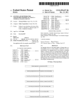
An apparatus and method for telephony tone signal and char
ABSTRACT
US. Cl. ................... .. 379/368; 379/52; 379/356.01;
acter code generation for QWERTY keyboards includes a
379/374.02; 400/485; 400/486; 400/489;
345/ 1 68; 345/169
QWERTY style keyboard, a processor and a keyboard mode
control software module. The QWERTY style keyboard has a
Field of Classi?cation Search .................. .. 379/52,
plurality of letter keys, Wherein each letter key is con?gured
379/356.01, 368, 374.02, 433.07; 400/485,
400/486, 489; 345/ 168, 169
See application ?le for complete search history.
to generate a unique input signal. The processor is coupled to
the keyboard and is con?gured to convert each unique input
signal generated by the letter keys into a character code and/or
(56)
a telephony tone signal. The keyboard mode control software
module operates on the processor, and controls Whether the
References Cited
processor converts the unique input signals from the letter
U-S- PATENT DOCUMENTS
4,430,639 A
2/1984 Bennett et a1.
4,503,288 A
3/1985 Kessler
‘3\
m
W’ 0
10
keys into character codes or telephony tone signals.
13 Claims, 7 Drawing Sheets
m
(3)
m
w
E
R
(a)
19)
(8)
<41
(61
11)
Y
u
1
0
P
(2)
(7)
(3)
(3)
(4}
(4)
(5)
(s:
(s)
A
s
0
F
G
H
J
K
L
*
(9)
19)
(a)
(a)
(2)
l6)
(6)
Z
x
c
v
B
N
M
H
US 8,391,468 B2
Page 2
US. PATENT DOCUMENTS
2123312455‘
2
1
1
5,581,593 A
5,606,712 A
5,611,031
5,660,488
D383,756
5,672,108
A
A
S
A
D386,497 S
lg?ggg gug‘mo
“mt
6,047,196 A
HeItZfeldetal.
.
Miller
Henderson et a1.
Lamet
a1.
.
9/1998 Yuen
. etal.
S
A
A
A
S
10/1998
10/1998
10/1998
11/1998
12/1998
Chiet al.
Grover
et a1.
.
Will
Abraham
.
Pa‘
5,848,356 A
12/1998
Jambhekar et al. ......... .. 455/403
4/1999 Stambolic et a1.
5,920,308 A
7/1999
5,931,373 A
8/ 1999 Cls?f _
9/1999
10/1999
10/1999
11/1999
11/1999
12/1999
1/2000
2/2000
Balaknshnan et a1.
Bacon etal.
Chase, Jr.
Weiseretal.
Sellers
PeretZ et a1.
LaPoIta et al.
Fullam et a1.
-
6,094,197 A
7/2000 BuXton et 31.
6,102,594 A
6,107,994 A
8/2000 Strom
8/2000 Harada et 31.
- et a1.
11/2000 Obradovlch
6,157,323 A
12/2000 Tso et al.
6,212,412 B1
4/2001 Rogers et a1.
6,218,966 B1
4/2001
6,241,406 B1
6/2001 Yan
6,429,855 B2
6662 020 B1
’
’
6,690,417 B1
6 965 372 B1
’
....... .. 340/731
8/2000 Ure
6,148,261 A
6,297,795 B1
Kim
4/2000
Makela e161.
4/2000 Scozzarella e161.
6,081,584 A
6,243,789 B1
.
5,893,798 A
4/2000 Nishimoto
4/2000 Aldridge et al.
4/2000 Klvela et a1.
6/2000 Hidaka
6,107,997 A
11/1997 Husllg et a1.
D397,728 S
A
A
A
A
A
A
A
A
6,052,070 A
2/1997 Hidaka
3/1997
8/1997
9/1997
9/1997
4/1998 Anderson
et a1.
.
8/1998 Rissman
5,952,942
5,963,197
5,974,238
5,982,520
5,995,026
6,006,351
6,014,429
6,023,779
6,049,697 A *
12/1996 Engelke
etal.
.
5,737,394 A
D397,369 S
D399,537
5,818,437
5,825,353
5,841,374
134031362
6,046,732 A
6,047,047 A
6/2001
- et a1.
Goodwin
Hasbun et 31.
10/2001 Kato et al.
8/2002 Pabon et al.
12/2003 ABIO 6161
-
'
2/2004 Yoshida et al.
110005 Woods
’
FOREIGN PATENT DOCUMENTS
EP
EP
0898222
0898222 A1
2/1999
“999
WO
99/37025 A1
7/1999
WO
WO
W0
WO9937025
00/30381 A1
WO0030381
7/1999
5/2000
5/2000
* cited by examiner
US. Patent
Mar. 5,2013
Sheet 1 of7
US 8,391,468 B2
IIJLBJI MIT“ 5 IMLZJLLIEAJUJ
l3\
(7)
m‘ (3)
N 0
(E)
g
10
A
*
(1)
E
w
[7)
(a)
R
(3)
(3)
S
0
F
(9)
Z
K9) (2]
x L E
(9)
(a)
(4}
G
(8)
v
(4)
u
Y
(6!
W
0
I
P
(4)
(S)
(5}
(5)
H
J
K
L
(2)
B
(6)
N
(6)
H
'1
®@®@®@@@@@M
®®®®®@@@@@M
®®®®®@@@@@
Q@®®®®@@@@@M
20
@
@
6@28®25@
Fig. 2
U S Patent
Mar. 5,2013
Sheet 2 of7
US 8,391,468 B2
®®®®® @@@@@PR
®®®®®®®®®Q
mmwmw;
33
3°
@
@
34
@mm
mwgs
34
Fi.3b
US. Patent
Mar. 5,2013
Sheet 3 of7
US 8,391,468 B2
US. Patent
Mar. 5,2013
Sheet 4 of7
US 8,391,468 B2
5
US. Patent
Mar. 5,2013
Sheet 5 of7
US 8,391,468 B2
mm
8{5
r
$M2756.03;$a329:5»m:
<
r\$5[a$721 3
2:523E“;:2mm5O2:589E5: an
g 5hi
f
505:35%;
:. v52 m.g E2E52?
A
4E“m
i
k
r
2%g7 $52l2
:5-5ga2s%?3
.I-“1$5.5
5:~2%52102;%51:5?2a A’.
5E25: 525
US. Patent
Mar. 5,2013
Sheet 6 of7
US 8,391,468 B2
E:L
2%m8if:‘-1.:H5v3:
a?2we532<
1,.-2$2pm:
5E2D E%
l
I
1
|
t
I
|
I
|
%\M5?25,v
.:3:m2i
Ar
wvV
US. Patent
Mar. 5,2013
Sheet 7 of7
US 8,391,468 B2
[ I2 L‘ ENTER MODE )
1 '4
USER HITS
1
A KEY
REHINU USER
?
YES
I 18 X
‘r
GENERATE souwu
,
GENERATE CHARACFER
AND/DR TONE SIGNAL
122
APPLICATION
FINISHED
'?
124
Fig. 8
A
US 8,391,468 B2
1
2
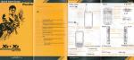
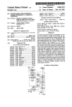
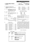
FIG. 2 is another exemplary multifunctional keyboard in
MULTIFUNCTIONAL KEYBOARD FOR A
MOBILE COMMUNICATION DEVICE AND
METHOD OF OPERATING THE SAME
Which the keys are arranged for optimal use With a hand-held
device;
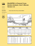
FIGS. 3a and 3b illustrate an additional exemplary multi
functional keyboard for a communication device in Which a
CROSS-REFERENCE TO RELATED
APPLICATION
plurality of character entry keys can function as either letter
entry keys or number entry keys;
FIG. 4 is a top perspective vieW of a mobile communication
This application is a continuation of the application titled,
“Multifunctional Keyboard For A Mobile Communication
Device And Method Of Operating The Same,” application
device utiliZing a multifunctional keyboard;
Ser. No. 10/004,001, ?led Nov. 1, 2001 , Which is related to the
nication device shoWn in FIG. 4;
FIG. 5 is a bottom perspective vieW of the mobile commu
FIG. 5a is a top vieW of an additional mobile communica
following prior application: “Apparatus And Method For
Telephony Tone Signals and Character Codes Generation For
tion device utiliZing a multifunctional keyboard;
QWERTY Keyboards Or The Like,” US. Provisional Appli
cation No. 60/246,321, ?led Nov. 7, 2000. This prior appli
cation, including the entire Written description and draWing
cation device shoWn in FIG. 5a;
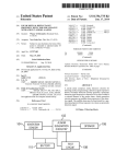
FIG. 5b is a side vieW of the additional mobile communi
FIG. 6 is a block diagram of an exemplary mobile commu
?gures, is hereby incorporated into the present application by
reference.
BACKGROUND
20
1. Field of the Invention
nication device utiliZing a multifunctional keyboard;
FIG. 7 is a How diagram illustrating an exemplary method
for controlling the operational mode of the multifunctional
keyboard in a communication device; and
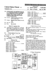
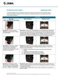
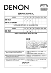
FIG. 8 is a How diagram illustrating the modes of operation
for the multifunctional keyboard.
This invention relates generally to the ?eld of keyboard
user interfaces. In particular, the invention provides a multi
functional keyboard for a mobile communication device and
method of operating the same.
DETAILED DESCRIPTION
25
Referring noW to the draWing ?gures, FIG. 1 is an exem
2. Description of the Related Art
Advances in communication technology have created a
convergence betWeen the ?elds of data and telephony com
munications. Traditional communication devices, hoWever,
typically include tWo separate interfaces; one for telephony
30
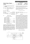
also corresponds to a number, although a different keyboard
style could be used such as a Dvorak or AZERTY keyboard.
communication, and one for data communication. Other
knoWn communication devices utiliZe the limited character
mapping available on a typical telephone keypad to perform
data entry functions. For instance, current telephone keypads
map keys to characters on a one-to-many basis: 12 keys (1, 2,
The number corresponding to a letter key 12 on the multi
40
functional keyboard 10 is preferably based on the number/
character correspondence on a traditional telephone keypad.
For instance, the number tWo (2) on a traditional telephone
keypad corresponds to all of the letters A, B and C. Similarly,
the letter keys A, B and C on the multifunctional keyboard 10
each correspond to the number tWo (2).
The multifunctional keyboard 10 is multifunctional in the
45
sense that it operates in at least tWo modes: a telephony mode
and a data mode. In the telephony mode, a key 12 pressed on
the multifunctional keyboard results in a telephony tone sig
nal for communicating With a voice communication netWork.
The telephony tone signal may, for example, be a Dual Tone
35
3, 4, 5, 6, 7, 8, 9, *, 0, #) correspond to 26 characters (ABC,
DEF, GHI, JKL, MNO, PQRS, TUV, WXYZ). In addition,
most such telephone keypads do not include many of the
characters from the American Standard Code for Information
Interchange (ASCII) character code. In other knoWn commu
nication devices, including many cellular phones, data may
be entered With a typical telephone keypad by repeatedly
pressing a key to cycle through a number of associated char
acter codes. For instance, repeatedly pressing the keypad key
Multi Frequency (DTMF) signal commonly used for dialing
“2” on a typical cellular phone may cycle through the char
acters A, B, C, a, b, c, and 2.
a phone number in voice communication netWorks. In the
data mode, pressing the same key 12 on the multifunctional
keyboard 10 Will result in the generation of a character code,
SUMMARY
50
In a preferred embodiment, the multifunctional keyboard
10 may also operate in a joint mode. In the joint mode of
operation, depressing keys on the multifunctional keyboard
letter keys, Wherein each letter key is con?gured to generate a
55
board and is con?gured to convert each keyboard output
signal generated by the letter keys into a character code and/or
a telephony tone signal. The keyboard mode control softWare
DTMF signal representing the number seven (7).
FIG. 2 is another exemplary multifunctional keyboard 20
60
in Which the keys are arranged for optimal use With a hand
held mobile communication device. The keys of the multi
functional keyboard 20 preferably comprise a QWERTY
style keyboard, although other keyboard styles could be uti
BRIEF DESCRIPTION OF THE DRAWINGS
FIG. 1 is an exemplary multifunctional keyboard having
keys that are mapped to both telephony tone signals and
character code signals;
10 results in the simultaneous generation of both telephony
tone signals and character codes. For example, pushing the Q
key may result in both an ASCII code for the letter Q and a
module operates on the processor, and controls Whether the
processor converts the keyboard output signals from the letter
keys into character codes or telephony tone signals.
such as an American Standard Code for Information Inter
change (ASCII) character code.
A multifunctional keyboard for a mobile communication
device includes a keyboard, a processor and a keyboard mode
control softWare module. The keyboard has a plurality of
keyboard output signal. The processor is coupled to the key
plary multifunctional keyboard 10 having keys 12 that are
mapped to both telephony tone signals and character code
signals. The multifunctional keyboard 10 is preferably a
QWERTY style keyboard in Which each of the letter keys 12
65
liZed, having a plurality of letter keys 22, a plurality of num
ber keys 24, specialiZed keys 26 and a space bar 28. Each of
the letter 22 and number 24 keys preferably correspond to a
character code While the keyboard 20 is in data (or joint)
US 8,391 ,468 B2
3
4
mode, and correspond to a telephony tone signal While the
keyboard 20 is in telephony (or joint) mode. In addition, one
emphasiZe the particular telephony signal and/or character
code to be generated by each key.
or more of the specialized keys 26 may have functions that
FIG. 4 is a top perspective vieW of a mobile communication
vary depending upon the mode of the multifunctional key
board 20. For instance, one specialiZed key 26 may perform a
“line feed” function While the keyboard 20 is in data mode,
and a “talk” function While the keyboard 20 is in telephony
mode. In addition, the multifunctional keyboard 20 may
device 40 utiliZing a multifunctional keyboard 3 0. The keys of
the multifunctional keyboard 30 are preferably uniformly
distributed across the device 40 such that approximately half
of the QWERTY keys are positioned on the left hand side of
the device 40, and the remaining half of the QWERTY keys
include one or more mode keys 29 that sWitch the keyboard 20
are positioned on the right hand side of the device 40. In
from one operational mode (telephony, data or joint) to
another.
FIGS. 3a and 3b illustrate an additional exemplary multi
functional keyboard 30, 31 for a communication device in
Which a plurality of character entry keys can function as either
letter entry keys 32 or number entry keys 35. Similar to the
multifunctional keyboards 10, 20 described above With ref
erence to FIGS. 1 and 2, this multifunctional keyboard 30, 31
addition, the QWERTY keys are preferably tilted at angles to
facilitate easy thumb typing While the mobile device is held
may operate in telephony mode, data mode, and possibly joint
mode. In addition, hoWever, this multifunctional keyboard
30, 31 utiliZes less keys by providing a letter entry mode,
betWeen the hands of a mobile device user.
FIG. 5 is a bottom perspective vieW 41 of the mobile
communication device 40 shoWn in FIG. 4. The communica
tion device 40 preferably includes an ear bud 42 that is detach
ably ?tted Within a cavity 44 in the device housing. The ear
bud 42 preferably includes a speaker portion 46 proportioned
to ?t Within the ear of a communication device user and a
microphone portion 48 that extends toWards the user’ s mouth.
20
When ?tted into the device user’ s ear, the ear bud 42 may, for
shoWn in FIG. 3a, and a number entry mode, shoWn in FIG.
example, be used to establish voice communication through
3b. While in letter entry mode, the keyboard 30 preferably
the mobile communication device 40. It should be under
comprises a QWERTY style keyboard 30, although other
stood, hoWever, that the mobile communication device 40 is
keyboard styles may be utiliZed, having a plurality of letter
not limited to embodiments having a detachable ear bud 42. In
entry keys 32, specialiZed keys 33 and a space bar 34. If a
letter entry key 32 is pressed While the keyboard 30 is in letter
entry mode, a telephony tone signal and/or a character code
corresponding to the letter on the key may be generated,
depending upon the operational mode (telephony, data or
joint) of the keyboard 30. When the keyboard 31 is in number
entry mode, hoWever, a number of the keys are remapped to
25
30
FIG. 5a is a top vieW of an additional mobile communica
provide a numerical keypad, preferably comprising a plural
ity of number entry keys 35, specialiZed keys 33, a space bar
tion device 40A utilizing a multifunctional keyboard 30. The
communication device 40A preferably includes a speaker
34 and a plurality of non-functional keys 3 6. If a number entry
key 35 is pressed While the keyboard 31 is in number entry
35
46A and a microphone 48A ?xedly mounted on the device.
When positioned near the device user’ s head, the speaker 46A
and the microphone 48A may, for example, be used to estab
lish a voice communication though the communication
mode, a telephone tone signal and/ or a character code corre
sponding to the number on (or represented by) the key may be
generated, depending upon the operational mode of the key
board 31 (telephony, data or joint).
Preferably, the character entry keys that function as both
number entry and letter entry keys, depending upon the entry
other embodiments, such as the embodiment described beloW
With reference to FIGS. 5a and 5b, voice communication may
be enabled With other means, such as a speaker and micro
phone ?xedly mounted on the device or an ear piece and
microphone connected to the device 40 through an electrical
terminal or jack.
40
device 40A.
FIG. 5b is a side vieW 42A of the additional mobile com
munication device 40A shoWn in FIG. 5a. The communica
tion device 40A preferably includes a jack 44A for connect
mode, have both a number and a letter printed on the key. For
ing a headset having an earpiece and microphone to the device
example, the “Q” key shoWn in FIG. 3a and the corresponding
40.
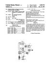
FIG. 6 is a block diagram of an exemplary mobile commu
“1” key shoWn in FIG. 3b Would preferably have both a “Q”
and a “I” printed on the key. The numbers shoWn in paren
45
theses represent the telephony tone signals corresponding to
The device 50 preferably includes a main module 53 and an
ear bud module 55. The multifunctional keyboard 51 is
the letter or number character, and Would preferably not be
printed on the key. It should be understood, hoWever, that
other printing arrangements are contemplated. In addition,
the keyboard 30, 31, or the communication device utiliZing
included in the main module 53 along With a tone signal
generation circuit 52, a keyboard mode control softWare mod
50
the keyboard 30, 31, preferably includes some means to indi
cate Whether the keyboard is in number or letter entry mode.
For example, When the keyboard 30, 31 is in one of the letter
or number entry modes, an icon may appear on a display, a
particular audible tone may sound When a key is pressed, an
55
alternative embodiment, hoWever, the processor 56 may be
replaced by an alternative processing unit, such as a ?eld
programmable gate array (“FPGA”) or a softWare interpreter
module.
the multifunctional keyboard 51 and converts these output
signals into telephony tone signals, character codes or both.
The mode of operation (data, telephony or joint) for the mul
activated.
In an alternative embodiment, the multifunctional key
60
tifunctional keyboard 51 is preferably determined by the key
board mode control softWare module 54 based on either the
current requirements of the device 50, a selection by the user
of the device 50, or possibly based on some other triggering
event. The keyboard mode control softWare 54 may, for
board 30, 31 may by represented on a display, such as a liquid
crystal display (“LCD”). In this embodiment, touching the
LCD Within the boundaries of a draWn key representation is
equivalent to pressing a key on the keyboard 30, 31. In addi
tion, an LCD embodiment of the multifunctional keyboard
30, 31 may include a function in Which the symbols displayed
on each draWn key change With the operational mode to
ule 54 operating on a processor 56, and a memory device 62
having a con?guration store 61 and a service store 63. In an
The processor 56 receives keyboard output signals from
LED may light, or some other indication means may be
board 30, 31 may be provided in conjunction With a displayed
softWare user interface. For instance, the multifunctional key
nication device 50 utiliZing a multifunctional keyboard 51.
65
example, set the device 50 to a particular keyboard mode
When a softWare application is executed on the device 50 and
possibly When a particular operation is executed by the soft
US 8,391,468 B2
S
6
Ware application. For instance, if an address book application
cessed to execute the call, and the character codes may, for
is executed, the keyboard mode control software 54 Will pref
example, be further processed to log the call.
The tone signal generation circuitry 52 may be used by the
erably automatically set the multifunctional keyboard 51 to a
preferred mode. When entering or editing an address book
entry, data mode is the preferred mode for editing or entering
a name, email address, or street address ?eld, Whereas joint
mode is the preferred mode for editing or entering a telephone
number ?eld. Conversely, When retrieving an address book
entry, data mode is the preferred mode for retrieving a name,
email address, or street address, Whereas either telephony
mode, joint mode or data mode may be the preferred mode for
retrieving a telephone number depending upon the purpose
for Which it is being retrieved. For instance, if a telephone
processor 56 to generate the telephony tone signals While the
multifunctional keyboard 51 is in telephony or joint mode. In
an alternative embodiment, hoWever, digital telephony tone
signals may be generated directly by the processor 56, or by
a digital signal processor. In addition to telephony tone sig
nals, the tone signal generation circuitry 52 may also generate
audible tones preferably at the option of the communication
device user. The audible tones may be used, for example, to
notify the user When a key is pressed on the multifunctional
keyboard 51. In alternative embodiments, the tone signal
generator may generate distinctive tones When a telephony
tone signal or character code is generated.
In addition to the components and softWare relating to the
multifunctional keyboard 51, the main module 53 also pref
erably includes a pair of antennas 58, 60 (although a single
number is retrieved from an address book in order to initiate
a voice communication, the number Will preferably be
retrieved in telephony or joint mode.
The con?guration store 61 and the service store 63 located
in the memory device 62 are preferably used by the keyboard
mode control softWare 54 to determine Which operational
mode (data, telephony or joint) is required for a particular
application. In a preferred embodiment, hoWever, the opera
antenna structure could be used), a memory device 62, an
20
tional mode of the keyboard 51 may also be selected or
overridden by a user of the mobile device 50. For instance,
With reference to FIG. 2, a mobile device user may preferably
select or trigger a change in the keyboard mode by pressing
ceivers 70, a poWer supply and recharging circuit 72, a cradle
interface circuit 74, and an auxiliary input device such as a
thumbWheel 76. The main module 53 may also include a
25
one of the mode keys 29.
Similarly, the letter entry or number entry modes for the
keyboard embodiment 30, 31 shoWn in FIG. 3, is preferably
also controlled by the keyboard mode control softWare 54.
Similar to the operational modes (data, telephony or joint),
the number and letter entry modes may be automatically
selected by the keyboard mode control software 54 based on
the application currently executing on the device 50, may be
selected by the device user, or may possibly be selected by
some other triggering event. For instance, if a voice commu
nication application is executed on the device 50, the key
board mode control softWare 54 Will preferably automatically
set the keyboard 51 to number entry mode (and telephony or
joint mode) so that a telephone number may be dialed. If the
user then desires to enter the telephone number using letters,
the user may preferably trigger the keyboard mode control
softWare 54 to sWitch the keyboard 51 to letter entry mode.
tion from a long-range Wireless netWork, and the one or more
short-range RF transceivers 60 are used to send and receive
information from the ear bud module 55, and possibly from
30
The ear bud module 55 is preferably an RF-enabled ear
piece that may be connected to (both mechanically and elec
35
78, a short-range Wireless transceiver 80, an antenna 82, a
rechargeable battery 84, and possibly an integral processor
86. Operationally, the short-range Wireless transceiver 80 is
40
45
50
55
mode, then the keyboard output signals are converted into
Once the call is initiated, the DTMF tones are further pro
used to establish an RF link betWeen the ear bud module 55
and the main module 53.
FIG. 7 is a How diagram illustrating an exemplary method
output signals to telephony tone signals and/or character
character codes, such as ASCII codes. If the communication
device 50 is in telephony or joint mode, then telephony tone
signals, such as DTMF signals, are generated. Then, as the
telephony tone signals and/ or character codes are generated,
they may be transferred to a buffer by the processor 56 to
aWait further processing. For instance, if a telephone number
is entered into the device 50 While the keyboard 51 is in joint
mode, then the character codes and DTMF tone signals for the
telephone number are preferably stored in a buffer until the
user initiates the call, for example by pressing a “send” key.
trically) the main module 53 as described above. The ear bud
module 55 preferably includes a microphone and a speaker
some other means.
codes. If the communication device 50 is in data or joint
other local devices such as an RF interface cradle, or a local
printer coupled to a LAN, or other types of printing or display
devices.
mode from a pull-doWn menu, pressing a specialiZed key,
holding doWn a key for a predetermined period of time, or by
Referring again to FIG. 6, once an operational mode (and
possibly one of the letter or number entry modes) for the
multifunctional keyboard 51 has been selected, either auto
matically or by a user, the keyboard mode control softWare
module 54 instructs the processor 56 to convert the keyboard
pressure-sensitive Writing tablet. Operationally, the long
range RF transceiver 68 is used to send and receive informa
For example, With reference to FIGS. 3a and 3b, the user may
be able to sWitch betWeen letter and number entry modes by
pressing the “NUM,” “CAP,” and/or “ALT” key, selecting a
LCD display 64, at least one rechargeable battery 66, a long
range RF transceiver 68, one or more short-range RF trans
90 for controlling the operational mode of the multifunctional
keyboard 51 in a communication device 50. This exemplary
method 90 may, for example, be executed by the softWare
mode control softWare module 54 described above. In step 92,
the communication device 50 is idle. The device 50 prefer
ably remains idle until the processor 56 receives a trigger in
step 94. The trigger may, for example, be initiated by an
unprocessed key stroke, the activation of a sWitch, an incom
ing message, an alarm condition, the activation of a softWare
application, or any other type of event that may be detected by
the device 50. For instance, the multifunctional keyboard 51
may include a specialiZed key that triggers a keyboard mode
change, or a mode change may be automatically triggered by
the detection of some event such as the activation of a soft
Ware application or a selection by the user of the device.
Once a mode change has been triggered in step 94, the type
of service (data, telephony or joint) required by the device 50
60
is determined in steps 96 and 100. The required service may
be determined, for example, by accessing the service store 63
locally maintained in a memory location 62 on the device 50.
The service store 63 preferably includes a log indicating the
type of service required by each softWare application on the
65
device 50 and also preferably includes a default service. For
the purposes of the illustration shoWn in FIG. 7, the default
service is the data mode. It should be understood, hoWever,
US 8,391,468 B2
7
8
that either the telephony mode or the joint mode could also be
the default service for the mobile device 50. In a preferred
embodiment, the system also accesses the con?guration store
user and stored in the con?guration store 61. Preferably,
noti?cation ?ags may be stored in the con?guration store 61
to either enable or disable the noti?cation function for the
61 maintained in the memory location 62 to determine if a
data, telephony and joint modes. If the noti?cation function
preferred mode has been selected for a particular application
or triggering event. The con?guration store 61 preferably
includes user con?gurable preferences relating to the modes
of operations. For instance, the con?guration store 61 may
indicate that the joint mode is preferred When the communi
has been enabled for the current keyboard mode, then the
device 50 generates an audible tone in step 118. In a preferred
embodiment, the audible tone generated in step 118 is differ
ent for each keyboard mode, thus enabling the device user to
determine the current mode.
In step 120, the device 50 generates a character code and/or
cation device 50 connects to a particular telephone number or
IP address.
telephony tone signal corresponding to the key pressed by the
In step 96, the system determines Whether the softWare
user and a corresponding keyboard output signal from the
application currently operating on the device (or other trig
gering event) requires the multifunctional keyboard 51 to
multifunctional keyboard 51. As described above, the signal
generated in step 120 depends upon the operational mode of
the multifunctional keyboard 51. If the multifunctional key
board 51 is in joint mode, then the system 50 generates both
operate in joint mode. If so, then the multifunctional keyboard
51 is set to joint mode in step 98. Otherwise, the device 50
determines Whether telephony mode is required in step 100. If
a character code and a telephony tone signal in step 120. If the
the current softWare application (or other triggering event)
multifunctional keyboard 51 is in telephony mode, then the
system 50 generates a telephony tone signal. If the multifunc
requires telephony mode, then the keyboard 51 is set to tele
phony mode in step 102. If neither joint mode nor telephony
mode are required, hoWever, then the multifunctional key
board 51 is set to data mode, its default mode of operation, in
20
generated. Once the appropriate character and/ or telephony
tone signal has been generated in step 120, the system 50
determines Whether the current application or other triggering
step 104. The modes of operation are detailed beloW With
reference to FIG. 8.
While the multifunctional keyboard 51 is in a particular
tional keyboard 51 is in data mode, then a character code is
25
event requiring the current keyboard mode is complete in step
122. If the application is complete, then the system exits its
operational mode, an asynchronous mode change may pref
current keyboard mode in step 124 and returns to an idle state.
erably be initiated upon the receipt of an additional trigger.
This type of mode change is asynchronous in the sense that
the change may preferably be initiated at any point during the
operational modes described beloW With reference to FIG. 8.
Asynchronous mode changes are illustrated in FIG. 7 by the
OtherWise, the system 50 remains in the current mode and
aWaits another keystroke at step 114. As Was described above
With reference to FIG. 7, hoWever, asynchronous mode
30
changed may occur from Within any step of FIG. 8.
In addition to the embodiments described above With ref
dotted lines from the three operational modes (steps 98, 102
erence to FIGS. 1-8, additional embodiments are contem
and 104) returning to step 94 at Which a trigger is received. If
plated Which alloW the operations of the multifunctional key
no asynchronous mode change is received, hoWever, the key
board 51 preferably remains in the same operational mode
board to be carried out on a loWer system level Without need
35
until the currently executing softWare application completes
its operations, at Which point the system returns to an idle
state at step 92.
In a preferred embodiment, more than one application may
be running on the device 50 at the same time, possibly requir
ing concurrent operation of more than one keyboard mode.
For instance, if several applications are executing on the
tion mode Wherein the mode control softWare translates key
40
storage. In such an embodiment, the mode control softWare
phony signals and/or output character codes, the input char
45
associated With the foreground application. Then, as the
device user (or the device itself) sWitches from the foreground
application to an idle application, an asynchronous trigger is
preferably generated to change keyboard modes. Preferably,
codes to telephony signals, and the key codes are provided by
voice recognition softWare recogniZing keys spoken by a
user, or, alternatively, the key codes being provided from
preferably translates input character codes to generate tele
device 51, one application may be in the foreground (the
active application) While the other applications are in the
background (the idle applications). In this instance, the mul
tifunctional keyboard 51 Will preferably operate in the mode
for an actual keyboard or a telephony tone signal generator.
For example, a communication device may include a transla
50
acter codes being interpreted as if they Were generated by use
of a multifunctional keyboard, thus enabling the communi
cation device to be easily adapted to a variety of sources of
input characters of Which a keyboard is but one example.
This Written description uses examples to disclose the
invention, including the best mode, and also to enable any
person skilled in the art to make and use the invention. The
before the device 50 sWitches from one application and asso
patentable scope of the invention is de?ned by the claims, and
ciated keyboard mode to another, the current mode associated
With the foreground application is stored in the service store
63. Then, When the idle application returns to the foreground
and becomes active, the stored keyboard mode associated
With the application is detected from the service store 63.
FIG. 8 is a How diagram illustrating the exemplary modes
of operation 110 for the multifunctional keyboard 51. In step
112, the device 50 enters a keyboard mode, such as the joint
mode, telephony mode or data mode. Then, When a device
user presses a key on the multifunctional keyboard 51 (step
114), the system 50 preferably determines Whether a user
noti?cation function has been enabled in step 116. The user
may include other examples that occur to those skilled in the
art.
55
1. A communication device, comprising:
tWenty-six keys that are each labeled With a different letter
of the alphabet and are each assigned a number;
the device being con?gured in a joint mode, for each key
60
determine the user noti?cation con?guration, the system 50
preferably detects one or more noti?cation ?ags set by the
pressed by a user, to simultaneously generate both a
telephony tone signal corresponding to the number
assigned to the pressed key and a character code corre
sponding to the letter assigned to the pressed key,
noti?cation function may preferably be con?gured by the
device user to generate an audible tone as a key is pressed. To
We claim:
Wherein the numbers 2-9 are assigned respectively to keys
65
A-C, D-F, G-I, J-L, M-O, P-S, T-V, and W-Z.
2. The device of claim 1, Wherein the keys are arranged in
a QWERTY con?guration.
US 8,391,468 B2
9
10
9. The device of claim 8, further comprising a mode key in
3. The device of claim 1, wherein the device is further
con?gured to output, for each key pressed by a user, a char
Which the user can sWitch from the ?rst mode to the second
acter code signal corresponding to the pressed key.
mode.
10. The device of claim 8, Wherein the device is con?gured
to indicate the mode of operation.
1 1. A method of operating a multifunctional keyboard for a
4. A communication device comprising:
twenty-six keys that are each labeled With a different letter
of the alphabet and are each assigned a number;
the device being con?gured in a joint mode to simulta
neously generate both a telephony tone signal corre
communication device, comprising the steps of:
providing tWenty-siX keys that are each labeled With a
different letter of the alphabet and are each assigned a
sponding to the number assigned to each key pressed by
a user and a character code signal corresponding to the
10
letter assigned to each key pressed by a user,
Wherein the numbers 2-9 are assigned respectively to keys
A-C, D-F, G-l, J-L, M-O, P-S, T-V, and W-Z.
5. The device of claim 4, Wherein the keys are arranged in
a QWERTY con?guration.
15
6. The device of claim 4, Wherein the numbers are commu
nicated through telephony tone signals.
A-C, D-F, G-l, J-L, M-O, P-S, T-V, and W-Z.
7. The device of claim 4, Wherein the numbers are commu
12. The method of claim 11, Wherein the numbers are
nicated through a display of the device.
8. The device of claim 4, Wherein the device has a ?rst
mode of operation in Which the device communicates the
numbers assigned to the pressed keys and a second mode of
operation in Which the device communicates the letters
labeled on the pressed keys.
number; and
in a j oint mode simultaneously generating both a telephony
tone signal corresponding to the number assigned to
each key pressed by a user and a character code signal
corresponding to the letter assigned to each key pressed
by the user,
Wherein the numbers 2-9 are assigned respectively to keys
communicated through telephony tone signals.
20
13. The method of claim 11, Wherein the numbers are
communicated through a display of the device.