1
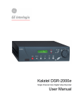
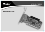
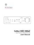
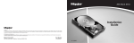
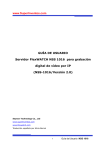
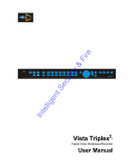
Kalatel DVSe Installation and Users Manual Warning! To prevent fire and electronic shock, do not expose this product to rain or moisture. The exclamation point, within an equilateral triangle, is intended to alert the user to the presence of important operating and maintenance (servicing) instructions in the literature accompanying the product. The lightning flash with the arrowhead symbol, within an equilateral triangle, is intended to alert the user to the presence of uninsulated “dangerous voltage” within the products enclosure that may be of sufficient magnitude to constitute a risk of electric shock to persons. ! Caution! To prevent electric shock, do not remove cover. No user serviceable components inside. Refer servicing to qualified service personnel. Caution! Lithium Battery Danger of explosion if battery is incorrectly replaced. Replace only with the same or equivalent type recommended by the manufacturer. ! Attention This product contains a recyclable lithium battery. It may be illegal to dispose of this battery improperly under local, state, or federal laws. Check with your local waste management officials for disposal and recycling options. Caution! Electrostatic-Sensitive Device! Use proper CMOS and MOSFET handing precautions, including approved grounded wrists straps, etc., to avoid damage to this unit or its internal components, from electric discharge. Warning! This equipment generates, uses and can radiate radio frequency energy, and if not installed and used in accordance with the instructions in this manual, may cause interference to radio communications. It has been tested and found to comply with the limits for a Class A computing device pursuant to subpart J of part 15 of FCC rules which are designed to provide reasonable protection against such interference when operated in a commercial environment. This equipment has also been tested and found to comply with the requirements for a CE Class A device and TUV safety standards. Operation of this equipment in a residential area may cause interference, in which case the user is required to take all measures that are necessary, at the user's expense, to correct the interference. Copyright Information Software and/or firmware is furnished to the purchaser under a license for use on a single system. Software and/or firmware included with this equipment are the sole proprietary property of, confidential to, and copyrighted by GE Interlogix, Corvallis, Oregon, USA. The software/firmware are not to be copied or disclosed in any manner without the express written consent of GE Interlogix. All information and specifications furnished by GE Interlogix are believed to be accurate and reliable. No responsibility is assumed by GE Interlogix for neither its use nor any infringements of rights of third parties that may result from its use. No license is granted by implication or otherwise under any patent or patent rights of GE Interlogix. The Kalatel™ brand name and product model numbers are the property of GE Interlogix. COPYRIGHT, 2003: The contents of this manual may not be copied or reproduced in any manner or form without the prior written consent of GE Interlogix. Kalatel DVSe 2 0150-0178F Table of Contents 1 Introduction ................................................................... 4 1.1 1.2 1.3 1.4 1.5 1.6 2 Hard Drive Installation................................................... 9 2.1 2.2 2.3 2.4 2.5 2.6 2.7 3 Opening The DVSe........................................................................... 9 Identifying The Components.............................................................. 9 Configuring Master/Slave ................................................................ 10 Mounting The Hard Drives............................................................... 10 Connecting the Hard Drives............................................................. 11 Compatible Hard Drives .................................................................. 12 Jumper Settings.............................................................................. 12 DVSe Setup .................................................................. 13 3.1 3.2 3.3 3.4 3.5 4 Product Description........................................................................... 4 Unpacking ........................................................................................ 4 Installation Environment .................................................................... 4 The Back Panel ................................................................................ 5 Connections...................................................................................... 5 Front Panel Indicators ....................................................................... 7 Connecting by SCSI or 1394 ........................................................... 13 Power-Up ....................................................................................... 14 Setup Menu .................................................................................... 14 Supervisor Menus ........................................................................... 16 Upgrading the DVSe ....................................................................... 17 Warranty and Service .................................................. 19 4.1 4.2 Factory Service............................................................................... 19 Warranty......................................................................................... 20 0150-0178F 3 Kalatel DVSe 1 Introduction 1.1 Product Description The DVSe is a rack mountable ethernet-ready high capacity digital video storage system. From 1 to 8 hard drives can be installed in each DVSe chassis. The unit may be purchased with or without hard drives installed. 1.2 Unpacking Check the package and contents for visible damage. If any components are damaged or missing, do not attempt to use the unit. Contact the supplier immediately. If the unit must be returned, it must be shipped in the original packaging. Package Contents • • • • • • • • • • • • The DVSe. US & EU Power Cables. The Kalatel DVSe Installation and Users Manual. The Kalatel DVSe Release Note. The Archiving Addendum Manual. WaveReader Software and Manual. WaveWatch Software and Manual. IDE Hard Drive Power Connectors x 2. (If shipped without drives installed) IDE Hard Drive Connection Ribbon x 4. (If shipped without drives installed) Hard Drive Fastening Screws x 24. (If shipped without drives installed) SCSI Cable, 50 HD to 50 HD. IEEE 1394 Firewire Cable. 1.3 Installation Environment Power: Ensure that the site’s AC power is stable and within the rated voltage of the external power supply. Ensure that a reliable Earthing path is maintained. This unit is designed to be connected to earth ground. If the site’s AC power is likely to have spikes or dips, use power line conditioning or an Uninterruptable Power Supply. Do not overload the circuit. Ventilation: Ensure that the location is well ventilated. Do not obstruct the cooling vents or fans. Temperature: Observe the unit’s ambient temperature specifications when choosing a location for the unit. Extremes of heat or cold beyond the specified operating temperature limits may cause the unit to fail. Do not install this unit on top of other hot equipment. Moisture: Do not expose the unit to rain or moisture. Moisture can damage internal components. Do not install this unit near sources of water. Kalatel DVSe 4 0150-0178F Rack Mount: Carefully load the rack so that it remains stable and unlikely to tip over. The unit is also suitable for desktop installation. 1.4 The Back Panel OFF ON 1 2 3 4 1: SCSI TERMINATION 2: SCSI POWER 3: BUZZER 4: AUX IEEE-1394 PORT 1 ETHERNET 10/100 PORT 2 SCSI PORT 1 SW 1 PORT 2 RS-232 RELAY OFF ON 1 2 3 4 5 6 7 8 Back Panel Components 1. 2. 3. 4. 5. 6. 7. 8. Cooling Fan: Do not obstruct. Power Connector, Voltage Selector and On/Off Switch. IEEE-1394 Firewire Ports 1 and 2. 10/100 Ethernet Port. SCSI Ports 1 and 2. Dip Switches (SW1). RS-232 Port. Alarm Out Relay Connection (Future feature). 1.5 Connections 10/100 Ethernet Port The Ethernet port is used to connect the DVSe into a network environment. Wire Type: Cat 5. Connector Type: RJ-45. Cable Required: Ethernet. SCSI Ports 1 and 2 Connect a SCSI device to one of the two SCSI ports. Set the dip switches (SW1) on the back panel. Set SCSI Termination and SCSI Power to On and use the Bus Select menu option to enable this feature. Connector: 50 pin, high density SCSI-2. Gender (on unit): Female. SCSI ID: 0. The unit does not currently support multiple SCSI device connections. 0150-0178F 5 Kalatel DVSe Caution! Ensure the power to DVSe is OFF BEFORE connecting any SCSI or 1394 devices. Do not attempt to use the SCSI and 1394 ports simultaneously. 1394 Firewire Ports 1 and 2 Connect a 1394 Firewire device to one of the two 1394 ports. Use the Bus Select menu option to enable this feature. Cable: 6 position IEEE 1394. Connectors: 6 position DIP. Dip Switches (SW1) Set the Dip Switches to enable or disable the features listed on the illustration to the right. Switch position up to turn off (disable), down to turn on (enable). OFF ON 1 2 3 4 1: SCSI TERMINATION 2: SCSI POWER 3: BUZZER 4: AUX RS-232 Port The RS-232 port can be used for Serial Debugging. Connector Type: DB-9. Gender (on unit): Male. Cable Required: Null Modem. DB-9 Pin Configuration For RS-232 Port Pin Use Pin Use 1 DCD 6 Not Connected 2 RX 7 RTS 3 TX 8 CTS 4 Not Connected 9 Not Connected 5 Ground NOTE To receive serial debug data from the DVSe’s RS-232 port, set up the receiving serial port at 57600 bps, No Parity, 8 data bits, and 1 stop bit. Kalatel DVSe 6 0150-0178F 1.6 Front Panel Indicators e 4 5 HARD DRIVES STATUS 1 PWR 1 1. 2. 3. 4. 5. 2 3 4 5 6 7 8 LNK ACTIVITY 2 RD WR 100 Kalatel DVSe ETHERNET 3 Power LED. Hard Drive Status Indicators. Ethernet Indicators. LCD Display. Key Pad buttons. Hard Drive Status Indicators (Green LEDs) LED On: Drive present and operating normally. LED Off: No drive present, drive not detected, drive disabled due to error. Hard Drive Activity Indicators (Red LEDs) The LED blinks when the drive is being accessed (read or write). Ethernet Indicators The ethernet LEDs light to indicate the following: • Link: A detected ethernet connection. • RD: Receiving Data. • WR: Transmitting Data. • 100: 100 Mbps bandwidth LNK RD WR 100 ETHERNET LCD Display Once power-up is complete, the LCD displays the total disk storage capacity of the unit. The LCD display also provides visual feedback for the menu settings. See DVSe Menu Setup for details. 0150-0178F 7 Kalatel DVSe Key Pad The Key Pad buttons provide access and control of the Setup Menu. • Up Arrow: Change field data (ascending). • Left Arrow: Move field selection to left. • Enter Button: Press to access setup menu. Toggles through menu screens. • Right Arrow: Move field selection to right. • Down Arrow: Change field data (descending). Kalatel DVSe 8 0150-0178F 2 Hard Drive Installation This section contains important information on adding or replacing the internal Disk Drives. Please read the entire section before performing any work. Caution: Do not allow any metal object to contact the motherboard. Do not allow loose screws to become lost inside the DVSe chassis. Wear an Electro Static Discharge protection device any time work is being performed inside the unit. 2.1 Opening The DVSe Before removing the cover, turn off the unit and unplug it. Using a Phillips-head screwdriver, carefully remove the twelve screws fastening the lid to the chassis. Save the screws and use them to refasten the lid when finished. 2.2 Identifying The Components Complete Internal Overview Power Supply Mother Board Drive Support Bracket Disk Drives 0150-0178F 9 Kalatel DVSe Motherboard Overview Power Supply Load Resistors Jumpers IDE Connectors IDE Power Connectors 2.3 Configuring Master/Slave IDE Connector #1 IDE Connector #3 IDE Connector #4 Disk 4 Slave Disk 3 Master Disk 2 Slave Disk 1 Master IDE Connector #2 Disk 5 Master Hard drives are connected in pairs to each of the four IDE connectors. Each pair of hard drives must be configured as a Master and a Slave. Configure the Master/Slave settings on each hard drive individually using the jumpers provided with the drive. Use the diagram located on the hard drive to determine the proper jumper configuration. If a single drive is connected to an IDE connector, it must be configured as a Master. 2.4 Mounting The Hard Drives Remove the Hard Drive Support Bracket. This entails removing the screws at either end and one screw from each installed hard drive. Orient the hard drive so that the IDE Power Connector is near the bottom of the chassis and facing the motherboard. Populate the drive array in order, starting from the left. Fasten the drive in place using the supplied screws. Fasten each drive using two screws through the bottom of the chassis and one screw in the Hard Drive Support Bracket. Kalatel DVSe 10 0150-0178F 2.5 Connecting the Hard Drives Power Supply Cables Connect the hard drives to the power supply connectors with power supply cables. NOTE Disk 8 Disk 7 Disk 6 Disk 5 Disk 3 Disk 2 Power Supply Disk 1 When connecting a single drive to a cable, attach the drive to the connector at the end of the power cable. Mother Board Disk 4 NOTE It is recommended, for ease of installation, that the IDE and power cables be first connected to the drives before the drive screws are tightened. The diagram above shows a typical connection. The connections may vary according to the number of drives in the system and the power cable type. IDE Data Cables Use an IDE cable to connect the drives as shown in the diagram in section 2.3. When attaching the IDE connector, make sure the connectors are oriented properly. Connecting To The Motherboard The red stripe on the connection ribbon should connect nearest the Pin 1 indicator on the motherboard. Pin 1 Indicator Connecting To The Hard Drive The red stripe on the connection ribbon should connect near the jumpers on the hard drive. 0150-0178F 11 Pin 1 Near Jumpers Kalatel DVSe 2.6 Compatible Hard Drives The DVSe is designed to be compatible with Maxtor D540X series hard drives. Hard drives in this series up to 250 GB may be used. Refer to www.maxtor.com for details. NOTE GE Interlogix cannot provide technical support for DVSe units using hard drives other than those described above. Using drives other than those described above may result in failure or intermittent data errors. Please contact GE Interlogix technical support regarding hard disk compatibility. 2.7 Jumper Settings Jumper Configuration Configure the jumpers based on the number of hard drives installed in the unit. Do not throw away unused jumpers. See section 2.2 to locate this block of jumpers. 1-7 Drives NOTE 8 Drives Load 4 Load 4 Load 3 Load 3 Load 2 Load 2 Load 1 Load 1 After any drives are installed, replaced or removed, the Reset Disk Failure command must be run from the Supervisor Menu for the changes to be recognized by the DVSe. Kalatel DVSe 12 0150-0178F 3 DVSe Setup This section contains important information on setting up the DVSe for operation. Please read the entire section before performing any work. 3.1 Connecting by SCSI or 1394 Caution! The DVSe does NOT support the simultaneous use of the SCSI and 1394 ports. Only connect one type of device at a time. SCSI Connect a SCSI device to one of the two SCSI ports using the supplied SCSI cable. Set the dip switches (SW1) on the back panel. Set SCSI Termination and SCSI Power to On. Select SCSI as the type of Bus in the Setup Menu under Bus Select. Caution! Power must be shut down before connecting SCSI cables between SCSI devices and the DVSe. Dip Switches (SW1) Set the Dip Switches to enable or disable the features listed on the illustration to the right. Switch position up to turn off (disable), down to turn on (enable). OFF ON 1 2 3 4 1: SCSI TERMINATION 2: SCSI POWER 3: BUZZER 4: AUX 1394 Firewire Connect a 1394 device to one of the two 1394 ports using the supplied 1394 cable. Set the dip switches (SW1) on the back panel. Set SCSI Termination and SCSI Power to OFF. Select 1394 as the type of Bus in the Setup Menu under Bus Select. Caution! Power must be shut down to all devices before connecting 1394 cables between the 1394 device and the DVSe. 0150-0178F 13 Kalatel DVSe 3.2 Power-Up Select the correct voltage before supplying power to the unit. Use the voltage selector switch located on the back panel of the unit, between the power connector and the On/Off Switch. Caution! Applying incorrect voltage could damage unit. Once the correct voltage has been selected and all connections have been made, connect the power cable suited to your geographic location. Apply power to the unit. 3.3 Setup Menu The Setup menu provides setup options for the following features: • • • • • • • Ethernet enable/disable. Bus Select: SCSI/1394 Auto Delete Mode. IP Address. Subnet Mask Address. Default Gateway Address. Date/Time Setup. NOTE Menus will automatically be exited after 30 seconds of inactivity. NOTE Access to menu is only allowed when the DVSe is Offline, i.e. the DVSe is not presently archiving or connected via ethernet. Press the Enter Button to access the first menu. Ethernet Enable Select ethernet enable, yes or no. Default setting is no. Bus Select Select from SCSI or 1394 to enable. Default setting is 1394. Kalatel DVSe 14 0150-0178F Auto Delete Mode Auto Delete Mode, select yes or no. Default setting is no. Auto Delete Mode automatically invalidates data that is over 30 days old. NOTE Obtain the required network addresses from you Network Administrator. NOTE The DVSe will automatically reboot if any of the Bus or Network parameters are changed. IP Address Enter the assigned IP address by using the left/right arrows to select the field and the up/down arrows to change the values. Subnet Mask Enter the assigned Subnet Mask address by using the left/right arrows to select the field and the up/down arrows to change the values. Default Gateway Enter the assigned Default Gateway address by using the left/right arrows to select the field and the up/down arrows to change the values. Date/Time Enter the current date and time by using the left/right arrows to select the field and the up/down arrows to change the values. Required only when Auto Delete Mode is set to yes. 0150-0178F 15 Kalatel DVSe 3.4 Supervisor Menus The Supervisor menus provides advanced options for the following features: • Serial Debug Output. • Disk Status. • Disk Failure Reset. The Key Pad buttons provides access and control of the Supervisor Menus. To access the Supervisor menus press the left and right arrows simultaneously. • Up Arrow: Quits the menu. • Left Arrow: Move field selection to left. • Enter Button: Press to access setup menu. Toggles through menu screens. • Right Arrow: Move field selection to right. • Down Arrow: Quits the menu. Serial Debug Serial Debug output, select yes or no. Default setting is no. Enabling serial debug will output debug messages on the RS232 port at 57600 bps. Changing this setting will cause the unit to restart. Disk Status This menu indicates the current disk status. Disk status is viewable only on this display. • N: Normal • W: Error writing to Disk • R: Error Reading Disk • T: Timeout during disk initialization or disk absent The letters on the Disk Status screen represent Disk 1 (left) thru Disk 8 (right). NOTE Do not attempt to reset a disk with read/write errors (a R or W status). This could lead to more disk errors and data loss. Disks with read/write errors should be replaced. Kalatel DVSe 16 0150-0178F NOTE Disks with a T status may be recovered, but the DVSe will attempt to start recording to this disk. A recovery should not be attempted until the preceding disk is filled up. Contact Technical Support for detailed instructions on replacing or recovering problem hard disks. NOTE Be sure to confirm that the drives are connected according to the diagram in Section 2.3 before removing or replacing. The disk status display and LEDs represent the wiring and Master/Slave configuration, not the physical location of the drives. Reset Disk Failure This command allows the DVSe to re-enable disks with timeout errors and reset the Disk Status. Changing this setting restart the unit. Any time that a disk is replaced, added, or removed this command must be executed. 3.5 Upgrading the DVSe Upgrading the software for the DVSe is accomplished via the ethernet port and a PC/Laptop equipped with a web browser. To properly upgrade the Kalatel DVSe the following preconditions must exist: 1. The Flash upgrade file and path. This file is obtained by calling Kalatel Technical Support at 1-800-469-1676. When calling, please have the following information available: q The model number of the product. q The serial number and revision of the product q The current firmware version. q The date purchased. q Symptoms of the unit that might require upgrade. 2. The DVSe unit connected to a PC equipped with Microsoft Internet Explorer version 5.5 or later via ethernet cable. 3. The IP address of the DVSe. 4. WaveReader software must NOT be connected to the DVSe. Please exit all non-essential software on the PC. 0150-0178F 17 Kalatel DVSe 5. Ensure that the DVSe is not currently recording or archiving. Follow the steps below to Upgrade the DVSe: Step 1. Launch the Browser software (Microsoft Internet Explorer 5.5 or later). Step 2. Enter the IP address of the DVSe in the address field of the Browser followed by /upgrade.ssi and press enter. For example if the IP address is 3.18.173.71 type 3.18.173.71/upgrade.ssi. Step 3. The Enter Network Password window should appear. Enter the correct Username and Password in their respective fields. (The default username is admin and the password is admin. It is recommended that the defaults be changed ASAP). Click the OK button. The DVSe upgrade page should appear. Step 4. Navigate to the upgrade file using the Browse button or type in the correct path and filename. Click on the Send File button. Step 5. Click on the Confirm Button. A progress bar will appear. PLEASE WAIT FOR THE PROGRESS BAR TO FINISH, THEN WAIT FOR CONFIRMATION! Step 6. Click on the Reboot button to restart the unit for changes to take effect. If unsuccessful, download the flash file again and retry the steps 1-6. Kalatel DVSe 18 0150-0178F 4 Warranty and Service 4.1 Factory Service If the unit requires factory service, contact the dealer who supplied the unit to you for the correct procedures on returning the unit to the factory or the nearest factory service center. If the dealer is not available, contact the manufacturer of the unit as detailed below and request a Return Material Authorization number (RMA). The unit’s serial number must be provided before an RMA number can be issued. Units returned to the factory for service must have freight and insurance prepaid, and must show the RMA number clearly on all shipping documents. The failure symptoms must be clearly described by the operator and enclosed with the unit together with a copy of the original supplier’s invoice. Failure to comply with these instructions will delay service of the unit, and may result in the unit not being accepted by the Repair Center. Factory Address GE Interlogix Attention: Repair Center 3197-C Airport Loop Drive Costa Mesa, CA 92626 United States of America Telephone: 800-343-3358 (7:00 AM to 4:30 PM, Pacific Time) In Oregon: 541-754-9133 Fax: 541-754-7162 (24 hours a day) For warranty information, see the following page. 0150-0178F 19 Kalatel DVSe 4.2 Warranty GE Interlogix warrants all of its equipment for three years from the date of purchase. This warranty covers any defects in materials and workmanship. Equipment failures that are due to improper installation, modification, abuse, or acts of nature will not be covered by this warranty. The repair department will evaluate all equipment returned for repair to determine warranty coverage. The Tech Support Manager will resolve any questions that may arise during evaluation to make a final determination. Note: The three-year warranty does not apply to the following products: ® MobileView and the monitor CRT, which carry a 12-month warranty from the date of purchase. The warranty specifically covers any defects in material and workmanship and does not cover equipment that has been abused, damaged, or modified. For all warranty repairs, GE Interlogix will cover all costs, including parts, labor, and shipping. Repaired equipment will be returned via the same method of shipment in which it was received. If a customer requests a faster return shipment, the difference will be charged. For all non-warranty repairs, the customer will be billed for parts, labor, and shipping. Labor will be billed in half-hour increments. Note: Customers requesting an estimate prior to repair will be notified by phone. If they cannot be reached, they will be notified by fax. If we are unable to reach the contact person for repair authorization after one phone attempt and two fax attempts, the equipment will be returned without being repaired. We will hold equipment no longer than two weeks. Advance Replacement Policy When an advance replacement is required, we will send the customer replacement equipment from our stock and receive the returned product in exchange. The received equipment will be evaluated and the repair department will determine whether it is a warranty replacement. If it is non-warranty, see our repair policy above for details. The following guidelines will be used for all advance replacements: • Fewer than 45 days from purchase, GE Interlogix will replace the product with new equipment. • From 45 days to 1 year from purchase, GE Interlogix will replace the product with refurbished equipment. • From 1 year to 3 years from purchase, the product must be sent in for repair. Advance replacements will be sent for a fee of $100. If you have questions about this policy, please contact the GE Interlogix RMA Department at 800-469-1676. Kalatel DVSe 20 0150-0178F