1
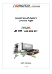
Vehicle Security System
GSM/SMS Pager
DS 512 ALARM - CAN GSM GPS
INSTALLATION MANUAL
ver.0.19 2015-03-13
Table of contents
1.
DS512 OPERATING PRINCIPLE ................................................................................................................. 5
2.
DS512 SET ............................................................................................................................................... 6
3.
PREPARATION OF SIM CARD ................................................................................................................... 7
4.
DS512 CONFIGURATION .......................................................................................................................... 7
5.
GSM PAGING PARAMETERS SETUP ....................................................................................................... 10
6.
DIAGNOSTIC TOOLS............................................................................................................................... 12
7.
PROGRAMMING OF TYTAN REMOTE TRANSMITTERS ........................................................................... 15
8.
BASIC SMS COMMANDS ........................................................................................................................ 15
9.
INSTALLATION OF DS512 ....................................................................................................................... 18
10.
INSTALLATION OF GPS RECEIVER........................................................................................................... 19
11.
PREPARATION OF THE DS512 TO WORK ................................................................................................ 20
12.
GIVING THE SYSTEM TO THE USER ........................................................................................................ 20
13.
TECHNICAL DATA .................................................................................................................................. 21
14.
DESCRIPTION OF INPUTS/OUTPUTS ...................................................................................................... 21
15.
PROGRAMMABLE AUX MODULE OUTPUT / CHANNEL .......................................................................... 21
16.
DS512 WIRING DIAGRAMS .................................................................................................................... 24
DIAGRAM 1 – MODE 3 AND MODE 4 - STAND-ALONE VSS ............................................................................. 25
DIAGRAM 2 – MODE 2 - MONITORING OEM CAN-BUS VSS ............................................................................ 26
DIAGRAM 3 – MODE 1 - PAGER FOR ANY THIRD PARTY ANALOGUE VSS ........................................................ 26
DIAGRAM 4 – MODE 1 - PAGER FOR ANY THIRD PARTY ANALOGUE VSS (INPUTS MONITORED) .................... 27
DIAGRAM 5 – CONNECTIONS FOR ANTI-HIJACK/REMOTE IMMOBILISER FUNCTION ...................................... 29
DIAGRAM 6 – CONNECTION FOR RF MODULE WITH TYTAN REMOTE TRANSMITTERS ................................... 30
DIAGRAM 7 – CONNECTION FOR SECOND ADDITIONAL SENSOR WITH PRE-ALARM ...................................... 31
DIAGRAM 8 – AUX MODULE........................................................................................................................... 32
2 tytan
TYTAN DS512 ALARM CAN GPS GSM features
• GSM-SMS pager integrated with CAN-bus Vehicle Security System central unit,
• alarming state signalisation with voice call or SMS in GSM network,
• vehicle GPS position is sent only during alarming or after DS512 receives a PIN protected SMS
command,
• if the vehicle GPS position cannot be fixed (e.g. vehicle in underground parking) the device sends
last known vehicle position
• remote (SMS) control of VSS and remote access to VSS trigger source memory,
• valet mode (service mode),
• operation mode as independent Vehicle Security System with CAN-bus connection
to vehicle electronic systems is armed/disarmed with OEM remotes or SMS commands,
• operation mode as GSM-SMS Pager monitoring for OEM security system via CAN bus,
• operation mode as GSM-SMS Pager monitoring for any analogue security system already installed
in the vehicle,
• device controlled with simple PIN protected SMS commands or by dedicated Android or iOS
application,
• operation with crash sensor (available only on certain markets),
• internal backup battery allows to notify users even after vehicle power supply breach,
• the device resends to the first programmed mobile phone number any
SMS received - e.g. sim card provider messages (option),
• vehicle low battery SMS signalisation (option),
• external AUX module with additional programmable output, for example to control auxiliary
heating (option).
Digital Systems 3
Vehicle Security System (VSS) features
• control by OEM remote transmitters
• control by additional Tytan remote transmitters (optional - only with external RF module),
• arming/disarming with SMS commands or dedicated Android or iOS application,
• signalisation if door / trunk / bonnet is open during arming (door ajar),
• when disarming - signalisation if the alarm was triggered,
• CAN-bus control of hazard lights, central door locking, power windows on some,
• analogue control of central door locking and power windows (optional - only with external RF
module),
• additional sensors input
- vehicle interior protection with ultrasonic motion detector (optional),
- vehicle towing and wheel theft protection with additional tilt sensor (optional),
• arming without additional sensors,
• state of the system is stored in non-volatile memory and is saved during power-off.
4 tytan
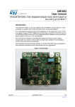
1. DS512 OPERATING PRINCIPLE
The DS512 is a device, that combines function of a SMS pager, complete Vehicle Security System
(VSS) and Anti-hijack device (only where the reg.97 UN ECE does not apply).
The general purpose of DS512 is to notify up to 3 mobile phone numbers with voice call or SMS
information containing status of vehicle and status of equipped security system.
The DS512, can be equipped with external GPS receiver. This allows to receive vehicle geographical
position in the form of latitude and longitude. SMS notification also includes a link to online maps,
which can be opened in any web browser to visualise vehicle position.
The localisation of the vehicle is set only when the alarm is triggered or if the dedicated SMS
command protected by individual DSPIN is sent to the VSS (see user manual).
The DS512 can work without alarm function (VSS) - without optical and acoustic signalisation
of alarming. The device works as a SMS pager that monitors OEM CAN-bus security system or any
third party or OEM analogue security system, already installed in the vehicle.
The 4 modes of DS512 operation are described below:
DS512 operating modes:
Mode 4 - FULL ALARM - complete CAN-bus VSS with audible and visible signalisation.
DS512 is the complete vehicle security system, controlled by OEM remote or Tytan remotes,
integrated with the vehicle via CAN bus.
In this mode the DS512 monitors the doors, trunk, bonnet and optional additional sensors or OEM
alarm system. When the device is triggered the acoustic (siren) and visible (hazard lights)
signalisation is started and GSM notification procedure is being started. Moreover, triggering of OEM
alarm (for example by OEM internal movement sensor) also triggers the DS512. The door, bonnet,
trunk, ignition and remote control signals are read from CAN bus (in some cars bonnet and trunk canbus signals may not be available). Analogue output allows to connect additional bonnet switch if the
vehicle is not equipped with OEM bonnet switch or OEM bonnet switch is not recognised on CANbus. The hazard lights negative output can control the hazard lights switch (perimeter connection)
or can control the relays of analogue connections to hazard lights bulbs. The siren and immobilisation
NC relay is controlled by negative output. The vehicle is immobilised when the VSS is armed and the
ignition is switched on.
The DS512 can be equipped with optional RF module (radio frequency module), which allows
to control the VSS with additional Tytan remote transmitters. The receiver module has 2 outputs, for
analogue control of central door locking (if Tytan remote transmitter is used) and for analogue power
windows control (any remote transmitter is used).
The proper wiring diagram for Mode 4 is diagram 1.
Mode 3 - SILENT ALARM – CAN-bus VSS without audible and visible signalisation.
The DS512 operates as in mode 4, but the audible and visible signalisation is disabled. The engine
immobilisation operates as in mode 4. The appropriate wiring diagram for Mode 3 is diagram
1 without siren and hazard lights connection.
Mode 2 - OEM PAGER – Pager for OEM CAN-bus security system
The DS512 works as a Pager, monitoring OEM VSS via CAN bus. Detection of alarming in the
monitored VSS causes the DS512 to notify up to 3 users via GSM about alarming. DS512 does not give
any audible or visible signalisation in this mode. The device does not react on opening the door
Digital Systems 5
or switching on the ignition as long as it does not trigger the OEM alarm. State of doors, ignition and
alarm state are read from vehicle CAN-bus.
The proper wiring diagram is diagram 2.
Mode 1 - PAGER – Pager for any third-party analogue security system
The DS512 operates as an analogue pager to any third-party analogue VSS installed in the vehicle.
The DS512 does not give any visible or audible signalisation. The DS512 does not monitor the doors,
trunk, bonnet and ignition unless violating any of these inputs triggers the monitored analogue
security system. Information of theft attempt is obtained from the monitored analogue security
system. The device has programmable trigger input which, depending on configuration, reacts
on positive signal +12V/+24V NO, positive signal +12V/+24V NC, ground signal NO, ground signal
NC. The signal must be at least 1 sec. long, in order to ignore short siren chirps if the DS512
is connected to the siren circuit.
If minimal connection of just the triggering circuit is used - the proper wiring diagram is diagram 3.
Moreover, in this mode, analogue connections of DS512 can be done to ignition circuit, door signal
and the VSS status signal. These analogue connections are not required, however they allow the
DS512 to monitor and send full status of the vehicle (door closed/opened, system armed/disarmed,
ignition on/off). If the VSS status signal is not connected the simplified information about vehicle will
be used. Ignition connection causes the GPS position to be saved during the drive. This is done
in case the vehicle would be parked in a place where the GPS signal is weak, e.g. underground
parking. Connection of door status allows to check remotely if the doors are closed or opened.
If the extended connection of the additional signals is used, the proper wiring diagram is diagram 4.
If the DS512 works in Mode 1 it is still possible to choose the CAN-bus level and connect CAN-bus
wires to the vehicle. This allows to read the door status and ignition from the vehicle CAN-bus
network and still monitor the analogue security system by analogue connections.
Remote stop / anti-hijack function.
In the countries, where the Reg. 97 ECE does not apply, in all the operating modes described above,
the DS512 anti-hijack function can be enabled. The anti-hijack sequence is triggered by the SMS
protected by a individual DSPIN. The anti-hijack sequence involves optical and acoustic signalisation,
and after several tens of seconds the vehicle is stopped. The immobilisation relay is active despite
the status of ignition.
In order to have the acoustic and visible signalisation during anti-hijack / remote stop procedure
in modes 1, 2 and 3 the siren and hazard lights connections must be done. These connections are
presented in the diagram 5.
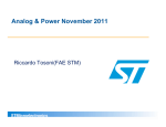
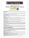
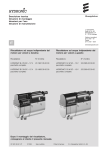
2. DS512 SET
1. main unit (SIM card not
included in set)
2. main wire harness
3. GPS module
4. immobiliser/anti-hijack module
5. LED/valet switch
6 tytan
3. PREPARATION OF SIM CARD
The DS512 can operate in GSM 900/1800 systems with any kind of SIM card. The only condition is to
disable the SIM card PIN code request or setting the SIM card PIN code to 6789 (e.g. with any mobile
phone).
If a prepaid SIM card is used please inform the user about the SIM card term of validity and the need
of maintain funds on the SIM card account in order to keep the possibility of making calls and
sending SMS by DS512.
SIM card phone number must be verified – this will be the vehicle number used for communication
with the DS512.
Some SIM card providers require to perform at least one voice call in order to activate the SIM card.
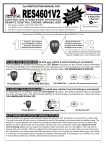
4. DS512 CONFIGURATION
The DS512 will operate in the vehicle only if it has been properly configured.
The configuration is made with a dedicated PC software and the mini USB cable.
The software panel has the list of programmable parameters and few buttons, described below.
- Read loads the configuration from DS512 and shows the settings from the device on the panel.
- Write saves the parameter values shown in the panel do the device.
Digital Systems 7
Parameter list:
1. Operating mode
The parameter selects the operating mode of DS512 as described above (analogue pager
/ OEM CAN-bus VSS Pager / Silent Alarm / Full Alarm).
2 - 4. Selection of vehicle type
In order to operate correctly with the vehicle CAN-bus in CAN-bus based modes 2, 3 and
4, the DS512 has to be programmed to a given vehicle model with so-called ‘CAN level’. The CAN-bus
level can be selected according to the table or the wiring diagram for a given vehicle. Moreover,
it can be selected automatically, by choosing make and model of the vehicle from the list. The list
is shown when the ‘make and model’ button is pressed.
5. Input active signal pager/bonnet
In modes 3 and 4 grey wire (PIN4) operates as an alarm triggering input, dedicated for connection
of additional analogue bonnet switch or other switch which protects the vehicle. In mode 1 (pager
mode) this wire operates as an analogue alarm-sensing input dedicated for detection of alarming
state of VSS installed in vehicle. In mode 2 this input is inactive.
The active signal of gray wire be programmed. The line can sense ground or positive signal. In case
of ground sense - the internal pull-up in DS512 is activated. In case of positive signal sense, the
internal pull-down is activated. Moreover, the line can react on applying the signal or lack of signal,
thus the NO or NC signals can be handled.
For example in NC- mode:
- the input is inactive as long as the ground signal is applied to the input.
- the input is active as long as s the ground signal is not applied to the input.
6. Pager signal length / time
Parameter allows to set minimal signal length of pager output. In mode 1 sensing a signal longer than
length set in programmer is recognised as vehicle violation – the procedure of SMS / voice call
notification starts. Default signal time is 500 ms (0,5 seconds). Choosing 0 causes immediate reaction
after signal is activated. To check the operation of pager output see ‘ALARM Pager’ lamp
in programmer signal monitor.
7. Hazard lights
The recommended method of hazard lights connection is ‘perimeter mode’ - connection
of dedicated DS512 active ground output (pin11 pink-black wire) to hazard lights switch circuit.
DS512 can also control the bulb circuits with analogue high current connection. In such case the
hazard lights connection should be set to ‘analogue’ and additional relays controlled
by pink-black wire must be used - see diagram 1 and diagram 5.
For some specific vehicles like Fiat and Alfa Romeo dedicated 1 wire digital control for hazard lights
and central door locks may be used. In such case set this parameter to ‘Fiat control’ and connect wire
pink-grey do the proper wire shown in Tytan installation schematics.
8. CAN-bus vehicle control
On some vehicles the DS512 can perform a CAN-bus control of:
- hazard lights (in this case the analogue or perimeter connection is not required),
- power door locks,
- power windows.
The information which vehicles allow for CAN bus control and which circuits can be activated
is present on the vehicle list and on wiring diagrams.
8 tytan
9. Audible confirmation of arming/disarming
IMPORTANT! Audible confirmation can be enabled only in countries where the Reg. 97 does not
apply. In opposite case, the homologation of DS512 as a VSS becomes invalid.
The parameter enables acoustic signalisation of arming/disarming VSS with short siren chirps.
10. Power windows roll-up
The parameter enables power windows roll-up when the system is armed. If the CAN-bus control
is enabled (p. 4.5) the device can control the power windows through vehicle CAN-bus. If the DS512
is equipped with external RF module with TYTAN remote transmitters, using this feature enables
a long pulse for windows roll up on the analogue door lock output in RF module).
11. Rearming
By default set to ‘Yes’ - in modes 3 and 4 - after disarming with remote transmitter / SMS command /
mobile app the security system waits 30 seconds for any door to be opened. If any door is not
opened during this time the system arms again (so called rearming). Setting this parameter to ‘No’
disables rearming – after disarming with remote transmitter / SMS command / mobile app the
systems stays disarmed until arming with remote transmitter / SMS command / mobile app. ‘No’
setting is recommended for vehicles / objects that do not have door switches.
12. Disarming by Tytan remote transmitters only
If set to ‘Yes’ parameter allows to operate in mode 3 and 4 as security system that can be armed by
OEM remote transmitter / Tytan remote transmitter / SMS command / mobile app, however
disarming is possible with Tytan remote transmitter / SMS command / mobile app. Disabling
disarming with OEM remote transmitters protects the vehicle with sophisticated theft methods –
cloning of OEM remote transmitters in order to disarm security system.
13. CAN-bus signal ignore codes
Parameter allows to ignore certain signals that appear on vehicle CAN-bus. It makes the system to
work correct in vehicles where CAN-bus lines send false signals or the device interprets CAN-bus
signals incorrectly. For example: opening the bonnet triggers OEM alarm in vehicle where OEM alarm
is not installed or rear doors are constantly opened in 2 door cars. Proper value of ignore parameter
is a sum of inputs: 1 – door front left, 2 – door front right, 4 – door rear left, 8 – door rear right, 16 –
trunk, 32 – bonnet, 64 – OEM alarm, 128 – ignition. For example door front left and ignition is 1 + 32
= 33. Default value 0 does not ignore any signals. Any ignored input is not signalised in programmer
signal monitor.
14. Anti-hijack / remote stop enabled
IMPORTANT! anti-hijack / remote stop can be enabled only in countries where the Reg. 97 does
not apply. In opposite case, the homologation of DS512 as a VSS becomes invalid.
The parameter enables the possibility to initiate anti-hijack sequence - execute remote vehicle stop
via SMS / mobile app. Anti-hijack procedure can be followed by audible and visible signalisation
(optional).
15. GPS receiver
By default the DS512 operates as SMS Pager with vehicle GPS localisation. The DS512 can also work
without the GPS receiver – then the GPS receiver should be disabled in the pc programmer in order
not to generate information about inability to fix GPS position.
Digital Systems 9
16. Programmable AUX module output / channel
DS512 can be equipped with external AUX module. It allows to use additional programmable output
OC type. Module allows to control external relays with SMS commands / mobile app. It allows
to control for example auxiliary heaters, trunk release or vehicle lights. Module operation and
working modes are described in chapter 15.
5. GSM Paging parameters setup
Press the GSM/SMS configuration tab to open the configuration panel. The panel allows
to set: number of mobile phones to be notified after an event, DSPIN code protecting from
unauthorised use of the device and the information sent in status messages.
1. DSPIN
It is a 5 digit PIN code protecting the DS512 against unauthorised access by SMS commands. The
commands and answers are described in DS512 User manual. DSPIN allows to send commands from
any mobile phone number. If commands are sent from any mobile phone number programmed in
position 3 to 5 in pc programmer the DSPIN is not required to execute the command.
2 - 5. Configuration of mobile phone numbers and notification types
Parameter 2 sets the number of mobile phones that will be notified after an event occurs in vehicle
(e.g. alarm trigger). Mobile phone numbers can be set in 3, 4 and 5. Number must be typed in
international format starting with country code, e.g. +48. Each of the programmed mobile phone
numbers can be individually programmed to receive notifications by voice call/dial, SMS
10 tytan
or notifications dedicated for TytanGPS mobile application (check www.tytangps.com for details).
If the operation of mobile application is enabled additional code starting with ‘#’ sign in included at
the end on each SMS sent by DS512.
6. Emergency number
On certain markets the device allows to operate with crash / accident sensor and notify the
emergency center after accident occurs. This parameter allows to check the emergency centre phone
number.
7. Number of voice call attempts
After DS512 is triggered it starts the alarm notification procedure. During alarming it calls the
programmed mobile phones. The call sequence repeats as follows: 1st mobile number - 2nd mobile
number - 3rd mobile number. This parameter allows to set number of call sequences: settings 1, 2 or
3 result in one, two or three call sequences.
8 - 12. Configuration
The DS512 sends SMS messages with vehicle and monitored VSS status during alarming and
as an answer to most received commands. The type on information in status messages can
be programmed in parameters 8 to 12.
Parameter 8 determines if ignition status should be included in status messages. Ignition status
is read either in analogue way (orange wire, PIN6) or via CAN-bus. Parameter should be set to YES.
It can be set to NO only when Mode 1 (PAGER, according to diagram 3) is used analogue ignition wire
is not connected and CAN-bus ignition is not monitored.
Parameter 9 determines if status message should include state of monitored VSS. This state is read
either in analogue way (blue wire, PIN3) or via CAN-bus. If parameter is set to YES the status message
includes information if systems is ‘armed’ or ‘disarmed’. Parameter should be set to YES. If it is set
to NO status message only gives a ‘ready’ information. This parameter may be set to NO only when
Mode 1 (PAGER, according to diagram 3) is used and blue wire (PIN3) is not connected to the
monitored VSS arm status wire.
Parameter 10 determines if status message should include state of doors, trunk or bonnet of the
monitored vehicle. These information are ready either in analogue way (blue/green wire, PIN5) or via
CAN-bus. Parameter should be set to YES. This parameter may be set to NO only when Mode
1 (PAGER, according to diagram 3) is used and blue/green wire (PIN5) and CAN-bus wires are not
connected to the vehicle
Parameters 11 and 12 allows to configure monitoring of the device power supply. If 11 is set to YES,
each status message includes information about device power supply source (internal battery
or vehicle battery). If parameter is set to ‘Detection of power supply’ and the power supply source
will change the device sends a status message containing information about power supply source
and voltage to every programmed mobile phone number. If parameter is set to ‘Detection of power
supply and low battery’ the device additionally monitors the power supply voltage. If the voltage
drops below a certain threshold a status message is sent by DS512 – it contains information about
power supply source and voltage. Moreover the threshold of voltage drop can be set in parameter
12. Three settings available, ‘12V’ monitors drop below 11V, ‘24V’ monitors drop below 22V, ‘other’
allows to set the threshold manually.
Digital Systems 11
13. SMS forwarding
Parameter allows to enable forwarding of SMS messages received by DS512 further to the 1st
programmed mobile phone number. Usually the SMS messages received by DS512 are information
from mobile operator. Please be aware that also all spam-like SMS would be forwarded as well!
14. Language
Parameter allows to change the language of SMS commands and received SMS information from
DS512.
IMPORTANT: the DSPIN and mobile phone numbers can and should be programmed by the user!
6. DIAGNOSTIC TOOLS
Press the Signal Monitor button - the panel visualising the CAN-bus and analogue input/output
signals with the indicators will be opened.
Columns 1-5 show the logic input/output signals - if the indicator lights up, it means that the signal is
active.
Lamp
LOCK
UNLOCK
UNLOCKTRUNK
ALARM
ALARM_OEM
12 tytan
Description
Locking the vehicle with OEM remote, with SMS command or mobile app was
detected. Locking command arms the VSS.
Unlocking the vehicle with OEM remote, with SMS command or mobile app
was detected. Unlocking command disarms the VSS.
Trunk release with OEM remote has been detected. It disables trunk, rear
door and additional sensor vehicle protection if the VSS is armed.
The DS512 operating as VSS has detected alarm condition and is alarming
(only modes 3 and 4) and started audible and visible alarm signalisation (only
mode 4). Each sensor triggers once in certain alarm state (until the
ALARM_STATE lamp goes off)
The DS512 has detected, that OEM CAN VSS has been triggered (only modes
2 and 4).
ALARM_PAGER
LOCK_STATE
LOCK_woTRUNK
DOOR (...)
TRUNK
BONNET (CAN)
BONNET (switch)
DOOR/TRUNK/BONNET
GLOBAL_IGNITION
IGNITION (CAN)
ACC (CAN)
STATUS1STATUS3+
SEND LOCK,
SEND UNLOCK,
SEND UNLOCKTRUNK
SEND HAZARD LIGHTS
SEND CLOSE WIN
PA button / ultrasonic
LED
ALARM STATE
EXT_SENSOR_INP
EXT_SENSOR2_PRE
EXT_SENSOR2
The DS512 has detected, that monitored analogue VSS has been triggered
and is alarming (mode 1 - analogue Pager) .
VSS system is armed / vehicle is locked.
VSS system is armed without trunk, rear door, additional sensor - the 3rd
button on remote has been used.
Door FL, FR, RL, RR is opened (only if monitored via CAN-bus).
Trunk is opened (only if monitored via CAN-bus).
Bonnet is opened - signal from OEM switch read from CAN-bus.
Bonnet is opened - analogue signal read via gray wire (pin4) in modes 3 and
4.
The lamp signals if any input is triggered. If the lamp is on, the door status in
SMS is sent as opened. In DS512 mode 1, diagram 4 (analogue pager) that
lamp shows the status of monitored VSS inputs.
The result of ignition signal - the sum of signals from CAN-bus and analogue
signal (orange wire).
Ignition switch signal read from CAN-bus.
ACC (ignition switch in accessory position) signal read from CAN-bus.
Status of additional analogue ground signal connected to blue wire (pin 4),
necessary for CAN-bus connections on some vehicles (e.g. Renault Clio).
Status of additional positive analogue signal connected to orange wire (pin
3), necessary for CAN-bus connections on some vehicles (e.g. Subaru
Forester).
The lamps show that DS512 is sending CAN-bus commands to the vehicle,
that control the vehicle circuits (power door locks, hazard lights, power
windows).
The lamp show that the PA button is pressed or the additional sensor input is
triggered (to disable additional sensors).
The lamp repeats the LED state.
Device is in alarm state - it is alarming or device waits 30 s after alarming last
arming. Only mode 4 – hazard lights signalisation in progress. When this lamp
lights up the notification procedure starts.
Additional sensor input is active
The lamp shows that additional sensor No2 Prealarm input was triggered.
The lamp shows that additional sensor No2 Alarm input was triggered.
Columns 6-7 show the status of device analogue inputs / outputs.
Lamp
OUT_IMMORELAY
OUT_HAZARD
OUT_SIREN
OUT_LED
AI0 (pin9),
DI0 (pin6), DI2 (pin4),
DI1 (pin3), DI5 (pin5),
Description
The lamp shows that the immobilisation relay output is active - connected to
ground.
The lamp shows that the hazard lights control output is active - connected to
ground
The lamp shows that the siren control output is active - connected to ground
The lamp shows that the LED control output is active - connected to ground
The lamps show the physical state at the given input. The lamp lights up if
the voltage at the input is positive. That is why the PA button and STATUS1inputs, which do have internal pull-up are displayed as active.
Column 8 shows the status of optional equipment: RF module with analogue central door lock
control outputs and external sensor No2 inputs
Lamp
RMT_LOCK
RMT_UNLOCK
Description
The lamp shows that LOCK button on Tytan remote transmitter was pressed
The lamp shows that UNLOCK button on Tytan remote transmitter was
pressed
Digital Systems 13
RMT_TRUNK
OUT_LOCK
OUT_UNLOCK
The lamp shows that UNLOCK_TRUNK button on Tytan remote transmitter
was pressed
The lamp shows that the central door locking analogue control output on RF
module is active - connected to ground
The lamp shows that the central door unlocking analogue control output on
RF module is active - connected to ground
Column 9 shows the signals for programmable optional AUX module
Lamp
AUX_SET
AUX_OUTPUT
AUX_STATUS
AUX_INPUT+
AUX_INPUT-
Description
Lamp indicates the expected state of the AUX output, resulting from the
information from the mobile phone (additional channel modes 1, 2, 4, 5, 6)
and automatic operation mode (additional channel modes 4, 5, 6)
Lamp indicates the actual state of additional output controlling relay. In
additional output modes 1, 3, 4, 5, 6 state of this lamp is equal as AUX_SET.
In mode 2 during pulse control, lamp AUX_OUTPUT indicates actual pulses
generated by the relay in order to enable / disable auxiliary heater
Lamp indicates what state/value of output is recognised by DS512 – this
state/value would be sent to the mobile phone. In modes 1, 3, 4, 5, 6 state of
this lamp indicates reference setting of AUX_SET and setting OC output
controlling the relay AUX_OUTPUT
In modes 2, 7 of additional output, this lamp indicates state of the auxiliary
heater or other electric circuit. This state is taken from inputs: white-yellow
or white-brown. AUX_STATUS is active if at least one of above mentioned
inputs is active.
Lamp indicates the state of AUX module white-yellow input. Lamp is on when
input is connected to +12V
Lamp indicates the state of AUX module brown-yellow input. Lamp is on
when input is connected to GND (ground)
Press the Diagnostics button to open the panel with GSM signal strength (CSQ), the information if the
GSM is registered in the GSM network, GPS signal quality (HDOP) and GPS data: latitude and
longitude. The green colour shows the values which are correct for the device to operate; red colour
shows the values which are insufficient for the device to operate correctly.
Parameter
GSM registered
GSM CSQ
GPS HDOP
GPS longitude
GPS latitude
Supply Voltage
14 tytan
Description
Value 1 means that the device is correctly registered in the GSM network.
GSM signal strength. Value 0 to 14 is weak. Value 15 to 24 is normal. Value
25 to 31 is strong. Value 99 means no signal.
GPS signal quality. Value <35 is sufficient
GPS position: longitude
GPS position: latitude
DS512 supply voltage
Press the Alarm Memory button. The panel with alarm
memory displays last 3 alarm trigger sources. The memory
can be cleared by pressing the ‘Clear’ button.
If the DS512 is equipped with optional RF module, press the RF module button to
open test panel with 2 controls.
The Save remote transmitters button starts programming procedure of Tytan
remote transmitters.
The RF module monitor control confirms reception of transmission from all remote
transmitters programmed into RF module. After receiving transmission from any
remote transmitter, the control lights up red for a second and number of the
remote in the RF memory is presented.
Moreover, the controls from the eight column (RMT_LOCK, RMT_UNLOCK, RMT_UNLOCKTRUNK) of
signal monitor can be used to test the buttons of remote control.
7. PROGRAMMING OF TYTAN REMOTE TRANSMITTERS
The DS512 can be equipped with additional RF receiver module, handling the Tytan remote
transmitters.
The RF module is automatically paired with DS512:
- when the DS512 is restarted. Please keep in mind, that to restart DS512 all power supply sources
must be disconnected: the main power supply, internal battery and USB connector.
- when the RF module button is pressed on the dedicated PC software and the RF receiver diagnostic
monitor is opened.
In order to program the remote transmitters, open the RF module panel and press
the Save remote transmitters button.
Now press simultaneously Lock and Unlock buttons on remote transmitter or
button on Joker token. The lamp lights up for a second. The remote transmitter /
Joker is programmed.
Then press the buttons/button on next remote. When the last remote is
programmed, press the End of programming button. The popup with number of
remotes programmed will be displayed.
8. BASIC SMS COMMANDS
The DS512 can be controlled by SMS commands sent from any mobile phone. The commands are
described in details in User Manual. The commands begin with 5-digit DSPIN code (Important! Not
to be confused with SIM card PIN!). The DSPIN code prevents DS512 from unauthorised access.
Default VSS PIN code is 12345. In this document, 2 basic commands, applicable for device testing will
be shown.
DS512 Status
Basic method of testing the DS512 SMS commands functionality is to send the command that require
the DS512 to respond with device status.
Digital Systems 15
{VSS PIN} status
For the new device:
12345 status
The device will respond with the status SMS, thus confirming the correct DS512 mobile number and
correct DSPIN code. The DS512 sends back the SMS with information on vehicle and security system
status. The information about status is sent in a full or simplified version, depending on settings
configured in the device during installation. In certain configuration if DS5412 works
in Mode 1 PAGER and monitors a VSS which does not allow to check the armed/disarmed state, the
simplified version of status message is sent. Full and simplified version of message contain hardware
and firmware version in order to facilitate technical support.
The full version of system status is:
system:
{disarmed / armed / armed w/o sensors /
armed w/o trunk and sensors / ALARM in
progress! / disarming / valet mode /
ANTI-HIJACK / ANTI- HIJACK vehicle stopped}
{ALARM was triggered!}
Door, trunk, bonnet: {closed / opened}
Ignition: {on / off}
Vehicle battery voltage = 12.08V
Power source: {vehicle battery / internal backup battery}
Meaning of each state:
disarmed
armed
armed w/o sensors
armed w/o trunk and sensors
ALARM in progress!
disarming
valet mode
ANTI-HIJACK
ANTI-HIJACK vehicle stopped
VSS is disabled, vehicle is not protected,
VSS is enabled, vehicle is protected,
VSS is enabled, additional sensors are disabled (e.g. ultrasonic
sensor, tilt sensor),
VSS is enabled, trunk compartment temporary not protected
and sensors temporary disabled due to the use of 3rd button on
OEM remote transmitter,
VSS is alarming; audible and visible signalisation enabled,
system was disarmed with OEM remote transmitter, waiting for
door to be opened or ignition to be turned on,
DS512 was set into service / valet mode thus the vehicle is not
protected,
DS512 received a command to immobilise the vehicle (anti-hijack)
function); vehicle is not immobilised yet,
DS512 received a command to immobilise the
vehicle (anti-hijack) function); vehicle is immobilised.
‘ALARM was triggered’ is displayed only if at the moment the VSS is armed and is currently not
alarming, but since the systems was armed the alarm was triggered at least one time.
16 tytan
The simplified version of system status is:
system:
{ALARM in progress! / ready / service mode / ANTIHIJACK! / ANTI-HIJACK vehicle stopped}
DS512 FW:xxxx yyyy
Meaning of each state:
ALARM in progress!
ready
valet mode
ANTI-HIJACK
ANTI-HIJACK vehicle stopped
VSS is alarming; audible and visible signalisation enabled,
VSS is not alarming, insufficient information to determine if system
is armed or not
DS512 was set into service / valet mode thus the vehicle is not
protected,
DS512 received a command to immobilise the vehicle (anti-hijack)
function); vehicle is not immobilised yet,
DS512 received a command to immobilise the
vehicle (anti-hijack) function); vehicle is immobilised.
Programming DSPIN code, number of mobiles phones to notify and GSM signalisation.
A dedicated command to configure notification methods, mobile phone numbers and DSPIN allows
to program these confidential settings individually by the user.
This command allows to change the DSPIN which protects the SMS commands to be executed
in DS512 and also allows to set the phone numbers which would be notified in case of alarm trigger.
0, 1, 2 or 3 phone number can be programmed.
{current DSPIN} setgsm {new DSPIN} {new DSPIN} {number of mobile
phones} {first phone number} {p1} {t1} {s1} {m1} {second phone number}
{t2} {s2} {m2} {third phone number} {t3} {s3} {m3}
current DSPIN:
new DSPIN:
number of mobile phones:
current (old)DSPIN code or default DSPIN code (12345),
DSPIN, which will be set as new code,
number of mobile phones which will be notified by voice call and/or
sms in the event of alarm trigger (0, 1, 2 or 3 phone numbers can be
programmed),
first, second and third phone number:
phone numbers which will be notified in the event of alarm trigger,
numbers in international format, ‘+’ at the beginning, for example
+CCCXXXXXXXXXX, (where CCC is the international country code, e.g.
+7, +81 or +359),
p1:
parameter enabling SMS forwarding – any SMS received by DS512
will be resent on the first mobile phone number,
t1, t2, t3:
parameters for voice call notification for given number, '1' enables
voice call notification, '0' disables voice call notification,
s1, s2, s3:
parameters for SMS notification for given number, '1' enables SMS
notification, '0' disables SMS notification,
m1, m2, m3:
parameter for activating or deactivating the operation with mobile
application, '1' enables application, '0' disables application,
important – if this parameter is set to '1' the SMS notification
(accordingly s1, s2 or s3) must be also set to '1' in order to the
application to run properly
Digital Systems 17
The confirmation of the command is the SMS with information:
DSPIN set: {new DSPIN} number of mobile phones: {number of mobile
phones}
{first phone number} resend:{yes/no} call:{yes/no} sms:{yes/no}
app:{yes/no},
{second phone number} call:{yes/no} sms:{yes/no} app:{yes/no},
{third phone number} call:{yes/no} sms:{yes/no} app:{yes/no}
Example:
12345 setgsm 54321 54321 3 +44501123456 1 1 1 0 +44502123456 0 1 0
+44503123456 0 1 1
sets new DSPIN to 54321 and 3 mobile phone numbers. These numbers will be notified after the
alarm trigger. First mobile phone number will be notified by voice call and SMS, second number just
by SMS, third number by SMS and operation via mobile application TytanGPS. The unit responds with
SMS confirmation:
DSPIN set: 54321 number of mobile phones:3
+44501123456 resend:yes call:yes sms:yes app:no,
+44502123456 call:no sms:yes ap:no,
+44503123456 call:no sms:yes ap:yes
9. INSTALLATION OF DS512
It is recommended to install the DS512 inside the vehicle, in a well hidden place with difficult access
for third parties, e.g.: under the dash, in the center tunnel, behind cover in trunk etc.
-
-
The DS512 cannot be exposed to water, gasoline, lubricants or other chemicals.
The device is not waterproof.
Due to the internal GSM antenna the installation location is restricted to have radio transmission
interferences – do not install the device in place heavily shielded with metal parts of vehicle
(inside closed metal sections).
Installation location should be chosen having regard to location of GPS module and wire harness.
After installation of the device but before re-assemble of side panels or covers the DS512
functionality must be tested!
18 tytan
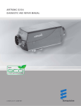
10. INSTALLATION OF GPS RECEIVER
The DS512 can be equipped with external GPS receiver integrated with GPS antenna. Correct
installation of GPS receiver is crucial for the precision of localisation and is determined by some
contradictory condition.
Due to security reasons, the receiver should be installed in a hidden place with difficult access for
third parties.
The GPS receiver cannot be covered with metal objects and should ‘see’ as much sky
as possible. The recommended installation place is the area directly under the dashboard, close to
the windshield in the central part of the dashboard.
-
-
The GPS module must be installed with the top side directed in the sky (horizontally). The top
side of module cannot be covered with metal parts.
Recommended location for GPS module is below the middle console.
The GPS module cannot be installed near the door/windows pillars as they may interfere and
decrease GPS signal strength and quality thus worsen the GPS localisation.
The GPS module can be installed bottom with magnet on metal parts of vehicle.
Sometimes, in the vehicles with glass covered by thin metalized layer, there is a need
to install the GPS receiver outside the cabin.
The GPS module wire needs to be lead to DS512 and fixed with zip-ties and/or insulating tape.
IMPORTANT! The GPS module installation should be verified at the device start-up procedure with
diagnostic monitor described above.
IMPORTANT! The time necessary to fix correct GPS position can reach up to few tens of seconds.
IMPORTANT! The GPS receiver is not waterproof!
Digital Systems 19
11. PREPARATION OF THE DS512 TO WORK
A. Prepare SIM card (chapter 2) and insert it into SIM card slot in DS512.
B. Connect the DS512 to the PC, run configuration software on PC. Proceed with the device
configuration (chapter 4 and 5).
C. Connect internal battery (if device is equipped) to a socket on the PCB.
D. Connect GPS module (module is integrated with GPS antenna).
E. Connect the main connector to the device. Enable power supply. Leave the USB connected (that
will start up the GPS even without alarming or localisation command).
F. Wait approx. 60 seconds.
G. During that period the device should start-up, register in GSM network and fix the GPS signal.
H. Use the PC software diagnostic panel to verify the installation of GPS module. Verify the GSM
registration and signal strength with a PC software.
Another fast method of checking if the device is registered in the GSM network is to make a call to
the DS512 from any mobile phone. The ‘call’ signal confirms that the DS512 is registered and
accessible in the GSM network.
12. GIVING THE SYSTEM TO THE USER
After the system is installed and checked, the user must be informed about operation of the system,
the meaning of DSPIN code and user is obliged to change individually: DSPIN code, mobile phone
numbers, number of mobile phones and to test operation of at least status or localisation SMS
command. After that the SMS Paging must be tested.
20 tytan
13. TECHNICAL DATA
Power supply:
Mean (300 seconds) power consumption at 12V :
Maximum sink current per single output:
Temperature range:
Alarming time:
9-30V
16mA
500mA
from -40°C to +85°C
30 sec.
14. DESCRIPTION OF INPUTS/OUTPUTS
Name
1
CANH
2
CANL
Active signal
3
STATUS1-
Input / Ground
ARMED
4
BONNET
PAGER
5
PA button / additional
sensors input
Other VSS input
monitoring
6
7
8
9
10
Ignition
STATUS3+
Input /
Positive
LED
Output /
Ground (1.5A)
Hazard lights
Output /
Ground (1.5A)
Immobilisation relay
Output /
Ground (1.5A)
Siren
Output /
Ground (1.5A)
12
14
Input /
Ground
Power supply
Not used
Not used
11
13
Configurable Input:
Ground or positive,
NO or NC
Ground
Function
Vehicle CAN-bus connection required to read information on
OEM remote, door status, ignition status, CAN-bus vehicle
control and others.
Mode 1:
input of ground signal informing, that monitored VSS is armed.
Modes 2, 3, 4:
analogue signal required to distinguish OEM remote signal in
some vehicles (e.g. Renault Clio).
Mode 1: Alarming detection input in pager mode, reacts on
signal longer than 1s.
Modes 2, 3, 4: Bonnet switch input, or other signal triggering
alarm if in armed mode.
Mode 1: Monitoring other VSS analogue input signals.
Modes 2,3,4: PA button input. Additional sensors input.
Modes 1,2,3,4 analogue ignition signal input.
Modes 2,3,4, - on some vehicles, which do have STATUS3+
icon in installation diagram analogue signal required to
distinguish information on OEM remote in some vehicles (e.g.
Mazda 3, Subaru Forester).
DS512 power supply 9-30V
Switched ground control of LED. In DS512 cable loom, there is
the resistor that limits the LED current.
Perimeter hazard lights control (hazard lights switch
connection) or hazard lights relays control signal (blinking) for
high-current bulb circuit connection.
Switched ground control of immobilisation NC relay. The relay
is activated when the alarming starts The relay is deactivated
when the VSS is disarmed.
Switched ground control of electronic siren.
DS512 ground
15. PROGRAMMABLE AUX MODULE OUTPUT / CHANNEL
DS512 may be equipped with programmable AUX module for additional output / channel.
The main purpose of this module is to enable and disable any object using SMS commands or
TytanGPS mobile app. An object can be, for example: auxiliary heater, lights or open the vehicle trunk
release. Additional AUX channel can be switched on permanently or for a specified period of time (up
to 999 minutes). If the additional channel operation is programmed, the DS512 transmits ‘AUX
Digital Systems 21
output status’ in each SMS with the status of the device. The module has several programmable
configuration modes dedicated to specific applications - auxiliary heater control, trunk release, lights
control for coming home and leaving home functions, etc.
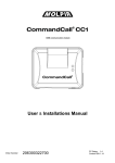
15.1.
AUX MODULE INPUTS / OUTPUTS
AUX module must be connected to the RF module socket on wire harness, that is to 3 pole white
connector. If there is a need to use both modules: AUX and RF at the same time – then the RF
module must be connected to the socket on AUX module.
AUX module has one OC type output, coming on black wire in 2 pole connector. White wire
is internally connected to the power supply. The connector fits the NO/NC relay included in AUX
module set.
AUX module has two inputs, they are used in mode 2 and 7 to control the switch state of device.
White-yellow input senses +12V, brown-yellow senses GND (ground).
15.2.
AUX MODULE OPERATION MODES
Mode 1 – input switched constantly or for programmed time
Basic operating mode for switching on and off any device, for example to control auxiliary heater
without built in timer or controller.
After receiving a switch on command the relay is switched on, accordingly permanently or for certain
time (from 1 second to 999 minutes).
The relay is being switched off either when the time goes out of a switch off command is received
by DS512.
In this operation mode ‘State of additional AUX output’ is status information sent by DS512 responds
to relay switch on or switch off state. White-yellow and brown-yellow inputs are ignored.
Mode 2 – control or auxiliary heater switch
Mode for devices that turns on and off with consecutive presses of single switch, that is by pulses on
single wire. Mode designed to control auxiliary heaters, either OEM heaters of aftermarket heaters
(like Webasto or Eberspaecher), equipped with internal timers/controllers or control switches with
indicator lamp.
AUX module relay circuit must be connected parallel to the auxiliary heater control switch.
To make the mode operational a proper signal (+12V or ground) must appear during activation
of auxiliary heater. It this case it may be a signal of auxiliary heater control lamp or OEM timer signal
that switches the heating unit. To control the heater only one of the wires must be connected, if the
control signal is +12V – use white-yellow wire, if control signal is ground use brown-yellow wire.
From the user side the operation of mode 1 is similar to mode 2. The heater is turned on after
receiving a switch on command: permanently or for certain time (from 1 second to 999 minutes). The
device is turned off after receiving switch off command or when the time goes out.
Operation of relay - switch on command
After receiving a switch on command DS512 checks AUX module status lines if the controlled device
is turned on or off.
- If the device is off, AUX module sends a pulse signal on relay control output. Relay enables the
device switch and auxiliary heater is switched on.
- If the controlled device is turned on during receiving switch on command, AUX module does not
send any pulse to the relay in order not to turn the auxiliary heater off.
Operation of relay - switch off command
22 tytan
After receiving a switch off command or the operation time goes out the DS512 checks AUX module
status lines if the controlled device is turned on or off.
- If the device is on, AUX module sends a pulse signal on relay control output. Relay disables the
device switch and auxiliary heater is switched off.
- If the controlled device is turned off during receiving switch off command of the turn off
command is received after programmed operation time is out, AUX module does not send any
pulse to the relay in order not to turn the auxiliary heater on.
In mode 2 the ‘state of AUX output’ sent to the user corresponds the checked AUX module status
lines and informs if the controlled device is turned on or off.
Mode 3 – trunk release control
In mode 3 the AUX module input operates as output for trunk release. It operates only if DS512 is
equipped with RF module and additional remote transmitters and DS512 is configured in MODE 3 –
SILENT ALARM or MODE 4 – FULL ALARM. Pushing the trunk release button on additional Tytan
remote transmitter results in turning the relay on for 1 second.
In mode 3 the AUX module relay cannot be controlled by SMS or TytanGPS mobile application
commands.
Mode 4, 5, 6 – vehicle lights control
In mode 4, 5 and 6 the AUX module output can control chosen vehicle lights circuit in order to use
functions:
- mode 4 – coming home – enables vehicle lights during arming of DS512
- mode 5 – leaving home – enables vehicle lights during disarming of DS512
- mode 6 – coming and leaving home - enables vehicle lights during arming and disarming of
DS512
The AUX module output is enabled automatically for 30 seconds. The functions operate with OEM
remote transmitters and Tytan remote transmitters. The lights go off 30 seconds after disarming of
the DS512 or after opening of vehicle doors. In these modes the vehicles lights can be turned on or
off remotely in any moment for certain time or constantly by SMS or TytanGPS mobile application.
However during arming and disarming of the system automatic control has higher priority than
remote control by SMS or TytanGPS app thus takes control of the output.
The coming home and leaving home functions are available only if DS512 operates in MODE 2 – OEM
PAGER, MODE 3 – SILENT ALARM or MODE 4 – FULL ALARM.
Mode 7 – additional input
In mode 7 the AUX module output is not used thus there is now way to control it. In this mode it
operates as additional input that uses one of the wires: white-yellow or brown-yellow to monitor the
state of any device or electric circuit in car.
Module implements the sum of both inputs: that means the AUX module sends an input trigger
information if any of the above mentioned inputs is triggered. Either +12V appears on white-yellow
or ground appears on brown-yellow wire.
State of the inputs is sent in every SMS or TytanGPS vehicle status.
15.3.
AUX MODULE MODES
The DS512 control lamps panel called ‘signal monitor’ contains all the lamps necessary to control or
diagnose the operation of additional channel. Meaning of each lamp is described in chapter 6 of this
manual.
Digital Systems 23
16. DS512 WIRING DIAGRAMS
Mode 4 – FULL ALARM – stand alone vehicle security system with audible and visible signalisation,
only GSM notification
- Standard connection, with remote immobiliser, with or without signalisation
diagram 1
- Additional connection of RF module with central door locking outputs
diagram 6
- Connection of additional sensor with pre-alarm (optional)
diagram 7
Mode 3 – SILENT ALARM – stand alone vehicle security system without audible and visible
signalisation, only GSM notification (with remote immobiliser, without signalisation)
- Standard connection, with remote immobiliser, without signalisation,
(without connections marked with *1)
diagram 1
- Standard connection, with remote immobiliser, with signalisation,
(with connections marked with *1)
diagram 1
- Additional connection of RF module with central door locking outputs
diagram 6
- Connection of additional sensor with pre-alarm (optional)
diagram 7
Mode 2 – PAGER OEM – monitoring of OEM CAN-bus VSS
- Connection monitoring VSS, input status and arm/disarm status
- Connection for remote immobiliser
diagram 2
diagram 5
Mode 1 – PAGER – monitoring of third-party analogue VSS
- Connection monitoring VSS alarming
- Additional connection for input status and arm/disarm status
- Connection for remote immobiliser
diagram 3
diagram 4
diagram 5
AUX module
- Connection for the AUX
diagram 8
24 tytan
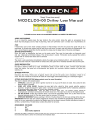
DIAGRAM 1 – Mode 3 and Mode 4 - stand-alone VSS
Digital Systems 25
DIAGRAM 2 – Mode 2 - monitoring OEM CAN-bus VSS
26 tytan
DIAGRAM 3 – Mode 1 - Pager for any third party analogue VSS
(ignition, door, armed signals are not monitored)
Digital Systems 27
DIAGRAM 4 – Mode 1 - Pager for any third party analogue VSS (inputs monitored)
(ignition, door and armed signals are monitored)
28 tytan
DIAGRAM 5 – connections for anti-hijack/remote immobiliser function
in all modes
Digital Systems 29
DIAGRAM 6 – connection for RF module with TYTAN remote transmitters
with analogue power door lock control in modes 3 and 4
30 tytan
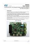
DIAGRAM 7 – connection for second additional sensor with pre-alarm
Digital Systems 31
DIAGRAM 8 – AUX module
32 tytan