1
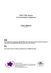
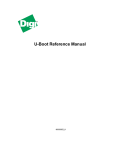
CAM-0100 Series Communication Appliance User′s Manual Revision: 1.2 CE This certificate of conformity of CAM-0100 series with actual required safety standards in accordance with 89/366 ECC-EMC Directive and LVD 73/23 ECC UL This product meets all safety requirements per UL60950 standard. Table of Contents Chapter 1 Introduction......................................................................................................... 2 1.1 About This Manual ................................................................................................ 2 1.2 Manual Organization............................................................................................. 2 1.3 Technical Support Information .............................................................................. 2 1.4 Board Layout ........................................................................................................ 3 1.5 System Block Diagram.......................................................................................... 3 1.6 Product Specification............................................................................................. 4 Chapter 2 Getting Started .................................................................................................... 5 2.1 Included Hardware................................................................................................ 5 2.2 Before You Begin.................................................................................................. 5 2.3 Hardware Configuration Setting ............................................................................ 6 2.4 The Chassis ........................................................................................................ 10 2.5 Open the Chassis ............................................................................................... 11 2.6 Hard drive Install ................................................................................................. 12 2.7 Thermal Pad Install ............................................................................................. 12 2.8 Remove and Install DIMM................................................................................... 13 2.9 Use a Client Computer........................................................................................ 15 Chapter 3 Boot-Loader Setting ......................................................................................... 17 3.1 Boot-Loader Information...................................................................................... 17 3.2 Key Commands in Boot-Loader .......................................................................... 19 3.3 Hardware Monitor in Boot-Loader ....................................................................... 20 3.4 Boot-Loader Update ............................................................................................ 20 Chapter 4 System Overview .............................................................................................. 22 4.1 System Memory Information ............................................................................... 22 4.2 System Watchdog Information ............................................................................ 22 4.3 SDK Patch Information........................................................................................ 23 4.4 By-Pass Driver Information ................................................................................. 23 4.5 Hardware Monitor Information ............................................................................. 25 4.6 System GPIO Information ................................................................................... 26 CAM-0100 Series User’s Manual 1 Chapter 1 Introduction 1.1 About This Manual This manual contains all required information for setting up and using the CAM-0100 series. CAM-0100 provides the essential platform for delivering optimal performance and functionality in the value communications appliance market segment. This manual should familiarize you with CAM-0100 operations and functions.CAM-0100-7616 series provide up to 2 on-board Ethernet ports and 1 switch with 4 ports to serve communication applications like Firewall, requiring 2 Ethernet ports to connect external network (internet), demilitarized zone and internal network. CAM-0100 series overview: Octeon 5020 500 MHz up to 2 Cores Memory: One DDR2 32bit SODIMM slot and up to 1G Two Gigabit Ethernet interfaces with one Bypass segments Independent management console(RS232) and Ethernet interface for MIPS64 system One min-PCI socket for mini-PCI device connectivity. One 2.5” SATA Hard disk 1.2 Manual Organization This manual describes how to configure your CAM-0100 system to meet various operating requirements. It is divided into three chapters, with each chapter addressing the basic concept and operation of this system. Chapter 1: Introduction. This section describes how this document is organized. It includes brief guidelines and overview to help find necessary information. Chapter 2: Hardware Configuration Setting and Installation. This chapter demonstrated the hardware assembly procedure, including detailed information. It shows the definitions and locations of Jumpers and Connectors that can be used to configure the system. Chapter 3: Operation Information. This section provides illustrations and information on the system architecture and how to optimize its performance. Any updates to this manual, would be posted on the web site: http://www.cas-well.com/products/index.php 1.3 Technical Support Information Users may find helpful tips or related information on Caswell's web site: http://www.cas-well.com A direct contact to Caswell's technical person is also available. For further support, users may also contact Caswell’s headquarter in Taipei or local distributors. Taipei Office Phone Number: +886-2-5591-1999 CAM-0100 Series User’s Manual 2 1.4 Board Layout Figure 1-1 Board Layout of CAM-0100 M/B 1.5 System Block Diagram Boot Bus CN-50x0 DDR2 533/667 SODIMM Socket CF 32/66 PCI PCI-to -SATA Bdg. 1x RGMII UART Realtek RTL8212 RGMII Switch Realtek RTL 8366 USB 2.0 2x RGMII MiniPCI SATA bypass GbE GbE 4 5 GbE 3 GbE 2 Figure 1-2 CAM-0100 Series User’s Manual GbE 1 GbE 0 Con- USB sole CAM-0100 Basic Block Diagram 3 1.6 Product Specification Feature Detailed Description Processor Cavium Octeon CN-5010/-5020 series Single and Dual MIPS64, L2 Cache128KB, Frequency 500Mhz. Memory Support 1x 200pin DDR2 32bit* SODIMM socket support DDR2 533/667 Max. Capacity up to 1GB 3 Bypass Ethernet ports Two Gigabit Ethernet ports with 1 bypass segments from RGMII interface of Octeon CN50xx with Realtek RTL8212 Ethernet PHY. 4 CF slot One CF slot for Operating system 5 SATA channels MiniPCI interface SATA channel for2.5” HDD connection One Mini-PCI connector on board 7 USB Support USB 2.0. 8 Ethernet ports 2 Gigabit Ethernet port (copper) from 50XX RGMII on CPU board. 1 Gigabit Ethernet port connect to a 4 ports Gigabit switch chip (RTL8366) 9 H/W Reset and Load Factory Default buttons There is a push button for H/W reset There is a l push button for F/D (Load Factory Default). 10 LED 1 * Power LED (Green) – in front 1 * Data Activity (Red). – in front 11 System H/W Monitoring The system will monitor CPU & System Temperature and operating voltage 12 Watch Dog Timer The WDT support 8 time-out intervals from 0.5 sec/Min to 64 sec/Max by s/w programming. 13 System Dimension 1U height, A5 size 210 (W) x 44 (H) x 148.5 (D) mm / 8.27” (W) x 1.73” (H) x 5.85” (D) 14 Environmental requirements Storage temp.: -20°C to 75°C Operating temp.: 0°C to 40°C. Humidity: 10 to 90% RH non-condensing 1 2 6 *Note: If insert 64 bit standard SODIMM, system can boot but memory will only detect half size System Feature Table System Model CAM-0100-7611 CAM-0100-7621 CAM-0100-7616 CAM-0100-7626 CPU 5010-500BG564SCP 5020-500BG564SCP RGMII GbE RGMII GbE Bypass USB CF Ports S/W ports Segment Mini SATA PCI Fanless 2 4 1 1 S S S -- 2 4 -- 1 S -- -- S 2 4 1 1 S S S -- 2 4 -- 1 S -- -- S *S: Support CAM-0100 Series User’s Manual 4 Chapter 2 Getting Started This section describes how the hardware installation and system settings should be done. 2.1 Included Hardware The following hardware is included in package: CAM-0100 Communication Appliance System Board One null serial port cable 2.2 Before You Begin To prevent damage to any system board, it is important to handle it with care. The following measures are generally sufficient to protect your equipment from static electricity discharge: When handling the board, use a grounded wrist strap designed for static discharge elimination and touch a grounded metal object before removing the board from the antistatic bag. Handle the board by its edges only; do not touch its components, peripheral chips, memory modules or gold contacts. When handling processor chips or memory modules, avoid touching their pins or gold edge fingers. Restore the communications appliance system board and peripherals back into the antistatic bag when they are not in use or not installed in the chassis. Some circuitry on the system board can continue operating even though the power is switched off. Under no circumstances should the Lithium battery cell used to power the real-time clock be allowed to be shorted. The battery cell may heat up under these conditions and present a burn hazard. WARNING! 1. "CAUTION: DANGER OF EXPLOSION IF BATTERY IS INCORRECTLY REPLACED. REPLACE ONLY WITH SAME OR EQUIVALENT TYPE RECOMMENDED BY THE MANUFACTURER. DISCARD USED BATTERIES ACCORDING TO THE MANUFACTURER’S INSTRUCTIONS" 2. This guide is for technically qualified personnel who have experience installing and configuring system boards. Disconnect the system board power supply from its power source before you connect/disconnect cables or install/remove any system board components. Failure to do this can result in personnel injury or equipment damage. 3. Avoid short-circuiting the lithium battery; this can cause it to superheat and cause burns if touched. 4. Do not operate the processor without a thermal solution. Damage to the processor can occur in seconds. 5. Do not block air vents. Minimum 1/2-inch clearance required. CAM-0100 Series User’s Manual 5 2.3 Hardware Configuration Setting 2.3.1 CAM-0100 System 12V DC USB Console 2x GbE MiniPCI 4x Switching ports CF Socket LED for Power status LED for Bypass & HDD LED for GbE and Gb Switching Ports CPU SODIMM Socket 2.3.2 CAM-0100 System Board Jumper In general, jumpers on CAM-0100 system board are used to select options for certain features. Some of the jumpers are configurable for system enhancement. The others are for testing purpose only and should not be altered. To select any option, cover the jumper cap over (Short) or remove (NC) it from the jumper pins according to the following instructions. Here NC stands for “Not Connected”. CAM-0100 Series User’s Manual 6 Location of Jumpers JP1、JP2: Bypass and Open Mode Selection Pin Function JP1(1-2),JP2(1-2) Short JP1(3-4),JP2(3-4) Short Bypass Mode Ì JP1(5-6),JP2(5-6) Short JP1(7-8),JP2(7-8) Short JP1(1-2),JP2(1-2) Open JP1(3-4),JP2(3-4) Open Open Mode JP1(5-6),JP2(5-6) Open JP1(7-8),JP2(7-8) Open JP3: CASEOPEN Detection and External Thermal Sensor Pin 1 3 Signal Name GND VTIN3 (from W83792G) CAM-0100 Series User’s Manual Pin 2 4 Signal Name CASEOPEN (from W83792G) MGND 7 JP4: Bypass and Normal Mode Selection Pin 1 3 5 Pin 1-3, 2-4 Short 3-5, 2-4 Short 4-6 Short Signal Name VDD_3V MODE_SEL GND Pin 2 4 6 Signal Name N.C WDT_STATUS GND Function Power on Default at Normal Mode , Mode Selection is S/W Programmable Ì Power on Default at Bypass Mode , Mode Selection is S/W Programmable Always at Normal Mode JP5: GPIO、TWSI and SMI Signals Pin Header from CAVIUM Pin 1 3 5 7 9 11 13 15 17 19 Signal Name OCT_GPIO_0 OCT_GPIO_1 OCT_GPIO_3 OCT_GPIO_12 OCT_GPIO_13 OCT_GPIO_14 OCT_GPIO_15 OCT_GPIO_16 TWS_SCL TWS_SDA Pin 2 4 6 8 10 12 14 16 18 20 Signal Name GND OCT_GPIO_17 OCT_GPIO_18 OCT_GPIO_19 OCT_GPIO_20 OCT_GPIO_21 OCT_GPIO_22 OCT_GPIO_23 MDI_MDC MDI_MDIO JP5: Bootloader Mode Selection Pin Function 1-2 Short Normal Mode Ì 1-2 Open Failsafe Mode JP6: Watchdog Timer Reset Pin Function 1-2 Short Enable WDT Reset (When WDT Expires) Ì 1-2 Open Disable WDT Reset JP7: Reset to Default Function Pin Function 1-2 Short Reset to Default 1-2 Open Normal Mode Ì CAM-0100 Series User’s Manual 8 JP8: Lattice JTAG (Bypass CPLD Program Header) Pin 1 2 3 4 5 6 7 8 Connector J1 J2 J3 J4 J5 J6 J7 J8 J9 J10 J11 J12 J13 J14 U1 SW1 SW2 D12 D13~D18 D19 Signal Name VDD_5V WDT_TDO WDT_TDI GND X WDT_TMS GND WDT_TCK Function DC Power Jack (12V) Console Port RGMII LAN Port 0 RGMII LAN Port 1 USB Connector COM2 Pin Header SATA Connector MiniPCI Socket DDR2 DIMM Slot CF Socket CAVIUM JTAG System FAN Connector +5V & +12V Power Connector (Only Output) Battery Connector RGMII Switch LAN Port 0~3 System Reset Button Reset to Default Button Power LED + HDD LED LAN LED Bypass LED Remark J6: COM2 Pin Header Pin 1 3 5 7 9 Signal Name TP_RS232_1_DCD RS232_1_RX RS232_1_TX TP_RS232_1_DTR GND Pin 2 4 6 8 10 Signal Name TP_RS232_1_DSR RS232_1_RTS RS232_1_CTS TP_RS232_1_RI N.C Pin 2 Signal Name J11: CAVIUM JTAG Pin 1 Signal Name EJTAG_TRST_L CAM-0100 Series User’s Manual GND 9 3 5 7 9 11 13 JTAG_TDI EJTAG_TDO JTAG_TMS JTAG_TCK EJTAG_RST_OD_L EJTAG_DINT 4 6 8 10 12 14 GND GND GND GND N.C VDD_3V J12: System FAN Connector Pin 1 2 3 Signal Name GND VDD_12V N.C J13: +5V & +12V Power Connector (Only Output) Pin 1 2 3 4 Signal Name VDD_12V GND GND VDD_5V J14: Battery Connector Pin 1 2 Signal Name VBAT GND 2.4 The Chassis The system is integrated in a 1U desktop chassis (Fig. 2-1, Fig. 2-2). On the front panel you will find a Power / HDD / Ethernet LED. Fig. 2-1 Front view of the chassis CAM-0100 Series User’s Manual 10 Fig. 2-2 Rear view of the chassis 2.5 Open the Chassis Loosen the 3 screws of the chassis, two are on the right/left side and one is on the bottom side then to remove the top cover The top cover can be removed from the base stand CAM-0100 Series User’s Manual 11 2.6 Hard drive Install The CAM-0100 system has supported SATA HDD function, please follow steps to install SATA HDD drive. 1. Use 4 screws to secure the drive into the hard drive bracket 2. Use 4 screws to secure the bracket into the chassis * Note: Fanless models do not supported 2.7 Thermal Pad Install The CAM-0100 system has supported fanless type, please follow steps to install thermal pad. 1. To clean the top and bottom chassis before install thermal pad 2. These thermal pad are high performance material, please do not touch pad directly by hand 3. There are two thermal pad, 80*60mm and 40*40mm, The big one is for bottom side use (between PCBA and chassis), and the other is for top side use (between top side and CPU heatsink). CAM-0100 Series User’s Manual 12 2.8 Remove and Install DIMM Follow these steps to upgrade RAM module: 1. Obliquity inserts the DIMM into the socket and depresses DIMM until the retaining clips back in place CAM-0100 Series User’s Manual 13 Follow these steps to remove a DIMM: 1. Pull the retaining clips of DIMM socket simultaneously to unlock the DIMM 2. Remove the DIMM from the socket CAM-0100 Series User’s Manual 14 2.9 Use a Client Computer Connection Using Hyper Terminal To access CAM-0100 via the console, Hyper Terminal is one of many choices. Follow the steps below for the setup: Note: Terminal software may need to update for correct console output. 1. Execute HyperTerminal under C:\Program Files\Accessories\HyperTerminal 2. Enter a name to create new dial 3. For the connection settings, make it Direct to Com1. 4. Please make the port settings to Baud rate 115200, Parity None, Data bits 8, Stop bits 1 CAM-0100 Series User’s Manual 15 5. Turn on the power of CAM-0100 system, after following screen was shown: This is the end of this section. If the terminal did not port correctly, please check the previous steps. . CAM-0100 Series User’s Manual 16 Chapter 3 Boot-Loader Setting 3.1 Boot-Loader Information After you boot the system, the Boot-Loader information (as figure below) will appear on the screen. Key messages will be shown on screen as following U-boot : Display the U-boot version and built time DRAM Information : Detect the DRAM clock and size CF card Profile : Detect the CF card model and capacity LAN : Display LAN port status of CAM-0100 system CAM-0100 Series User’s Manual 17 Help menu in Boot Loader “Help” menu is available handily by typing “help” CAM-0100 Series User’s Manual 18 3.2 Key Commands in Boot-Loader Fatls – Function: List files in directory When to use: To find the file in the CF card as “dir” command Usage : fatls <interface> <dev[:part]> [directory] Ex: #fatls ide 0 Fatload – Function: Load binary file from a DOS file system When to use: Update boot-loader or running OS or running test tool Usage : fatload <interface> <dev[:part]> <addr> <filename> [bytes] Ex: #fatload ide 0 $loadaddr ipfw Bootoct – Function: Boot from an Simple Executive ELF image in memory When to use: Running Simple Executive Usage : bootoct <addr> coremask=**** Ex: bootoct $loadaddr coremask=ffff Bootoctl – Function: Boot from a Linux ELF image in memory When to use: When you need to execute Linux image Usage : bootoctl $loadaddr coremask=**** Ex: bootoctl $loadaddr coremask=ffff Hmd – Function: Sensors display (Caswell) When to use: When you want to monitor system H/W status Usage : #hmd Run – Function: Run commands in an environment variable When to use: Want to update boot-loader or running Linux Usage : run linux_cf or run bootloader_update CAM-0100 Series User’s Manual 19 Reset – Function: Perform reset of the CPU When to use: Want to warm boot the system Usage : reset 3.3 Hardware Monitor in Boot-Loader The boot-loader support H/W monitor function Typing “hmd” on command line then will display current H/W status of the system FAN1; FAN2; FAN3; FAN4 can detect FAN rotational speed Temp1 can detect CPU temperature Temp2 can detect system temperature Temp3 not connected thermal sensor normally 3.4 Boot-Loader Update Follow below steps to update Boot-loader A. Make sure the normal.bin file has been saved to CF card B. Typing “#fatload ide 0 $loadaddr normal.bin” C. Typing “#run bootloader_flash_update” D. After update finishe, typing “reset” and press enter F. Boot-loader update finished CAM-0100 Series User’s Manual 20 CAM-0100 Series User’s Manual 21 Chapter 4 System Overview 4.1 System Memory Information DRAM Controller (LMC) The LMC is fully programmable to support the JEDEC DDR2 SDRAM specification (refer to JEDEC standard: DDR2 SDRAM Specification JESD79-2B (Revision of JESD79-2) January 2005). The LMC has a 32/16-bit-wide interface (36/18 bits wide with optional SECDED ECC), and can architecture support up to 16GB of SDRAM with date rates of up to 667 MHz There is a single address bus shared by all the DIMMs/parts Main Memory DRAM Addressing: All cached DRAM memory resides in an architected 36-bit address space that is in the lowest physical addresses. The first CN50XX implementation can contain up to 16GB of physical addresses available in the following physical address ranges DR0: 0x0 0000 0000 0000 to 0x0 0000 0FFF FFFF = low 256MB of SDRAM DR1: 0x0 0004 1000 0000 to 0x0 0004 1FFF FFFF = mid 256MB of SDRAM DR2: 0x0 0000 2000 0000 to 0x0 0003 FFFF FFFF = upper 15.5GB of SDRAM With 256MB of SDRAM or less, only DR0 is present. With 256MB - 512MB of SDRAM, DR0 and DR1 are present With more than 512MB of SDRAM, DR0 and DR1 are present in entirety; and the lower portion of DDR2 is present, according to the amount of SDRAM attached 4.2 System Watchdog Information A watchdog timer is a computer hardware timing device that triggers a system reset if the main program, due to some fault condition, such as a hang, neglects to regularly service the watchdog. The intention is to bring the system back from the hung state into normal operation. CAM-0100 features a watchdog timer that resets the CPU or generates an interrupt if the processor stops operating for any reason. This feature ensures system reliability in industrial standalone or unmanned environments. Location: JP6 Pin Define: Pin Function 1-2 Short Enable WDT Reset (When WDT Expires) Ì 1-2 Open Disable WDT Reset CAM-0100 Series User’s Manual 22 4.3 SDK Patch Information Since some hardware circuit design is difference between Caswell board and OCTEON board. Caswell will provide software patch file for OCTEON SDK used This file will explain how to install Caswell SDK patch, including basic building procedure and advanced building procedure. After patching the original OCTEON SDK, Caswell related board could have their proper customized configurations. The patch files cover Boot loader, Simple Executive lib and Linux kernel, for more details please check readme document in the patch file. 1. How to install: Make sure you have the original Cavium Octeon SDK sources. Copy or move the original SDK to a suitable path(say the path is <SKD_DIR>) and select a CASWELL target model you want to bring up (say is <CASWELL_MODEL>). All the supporting models can be obtained by run: "sh auto_patching.sh -h" or "sh auto_patching.sh help" Then you could assign above two parameters and run this auto patching script: "sh auto_patching.sh <SKD_DIR> <CASWELL_MODEL>" example: "sh auto_patching.sh /opt/OCTEON-SDK_1_8_1_294 capk-0100nd" The patching result would be showed in the terminal. If done, the current <SKD_DIR> could contain the CASWELL software updating code. 2. Bootloader In image/u-boot, we have been putting the bootloader binary into dedicated version directory. You could simply get one there and do the bootloader upgrading. 3. Linux Kernel 3.1 Basic building procedure: Enter the linux folder and run: "make kernel" "make strip" 3.2 Advanced building procedure: Indeed, all of the <CASWELL_MODEL> share the same kernel code base. So, you could use "make menuconfig" to pick up a suitable configuration to build your new kernel image. We will add the 'CA Patch Support' item under configuration table and list how to configure it in the document "OCTEON_SDK181_CASWELL_RELEASE_NOTE.pdf". 4.4 By-Pass Driver Information CAM-0100 has supported By-Pass function. It is follow Caswell By-Pass Gen1.5 Hardware design rule. All of the feature should be meet By-Pass 1.5 specification. The By-Pass function is controlled by board jumper setting and software programming Caswell network bypass driver package offer a software configuration solution for Caswell network bypass modules. It would contain the driver, sample scripts and user manual for detail exposition. 23 CAM-0100 Series User’s Manual [Driver Building] Make Bypass Control Driver: Our By-Pass driver can support Intel X86 and Cavium platforms. For CAM-0100 used you need to do: # cd casswell_bypass/driver # make KSRC=.. CC=.. TARGET=mips_cavium Ex: #make KSRC=/usr/local/Cavium_Networks/OCTEON-SDK/linux/kernel_2.6/linux CC=/usr/local/Cavium_Networks/OCTEON-SDK/tools/bin/mips64-octeon-linux-gnu-gcc LD=/usr/local/Cavium_Networks/OCTEON-SDK/tools/bin/mips64-octeon-linux-gnu-ld TARGET=mips_cavium [Installation Steps]: #insmod network-bypass.ko board=CAPK0100ND [Command description]: The following introduce the bypass driver information get/set API, we use system files to handle those. The easiest way is using “echo” and “cat” to do this. Sure, the file open and read/write these system file could be also using. Notice: The bypass hardware implement has several generations. The default function descriptions would focus on generation 2. And the hardware generation 1.X has some function differences; we list these as below (Table 5). Also, at each command description note, we list the file operation inconsistence there. By-Pass GEN1.X Function BYPASS 1. Only support normal and non-normal mode changing by software. 2. At non-normal mode, we could change open and bypass mode by hardware jumper setting. BPE According to hardware jumper setting. NEXTBOOT According to hardware jumper setting. Set BYPASS mode: Set to Normal: #echo 0 > /sys/bus/i2c/devices/0-002X/bypass0 Set to Open: #echo 1 > /sys/bus/i2c/devices/0-002X/bypass0 Set to Bypass: #echo 2 > /sys/bus/i2c/devices/0-002X/bypass0 *Note: At GEN1.x, we only support normal and non-normal mode change. “echo 2 > …” is invalid and no use. Get BYPASS mode: #cat /sys/bus/i2c/devices/0-002X/bypass0 Î bypass0 value: 0 Î normal, 1Îopen, 2Îbypass *Note: At GEN1.x, we could only get normal (0) and non-normal (1) status. We may need to check hardware jumper to see the setting is open or bypass. CAM-0100 Series User’s Manual 24 4.5 Hardware Monitor Information CAM-0100 has hardware monitor feature. It can detect voltage, fan speed, CPU temperature of board function. The chip of hardware monitor is Winbond 83792G and The SDK kernel has support it. Normally, W83792G is work on bootloader of Caswell SDK patch, you can press ‘hmd’ command under bootloader to know system hardware monitor status but if you want to know status under Linux kernel, you should enable this chip driver via SDK kernel item. Install hardware monitor driver: A. patch caswell SDK file B. make menuconfig to enable W83792 /usr/local/Cavium-Networks/OCTEON-SDK/linux/kernel2.X/linux/ CAM-0100 Series User’s Manual 25 C. make Linux kernel 4.6 System GPIO Information CAM-0100 has GPIO pin header on the board. OCTEON SDK also can support GPIO function. Caswell_util_octeoin-gpio package is a useful tool for set/get Cavium OCTEON GPIO configuration. About the detail usage, please refer to the octeon-gpio_util help menu. There are two files in the utility package. The octeon-df_test is a factory default setting sample for Cavium Octeon. It will present the GPIO7 setting to decide if user push the factory reset-default button. You could follow the sample code to implement system default function. The octeon-gpio_util is a gpio function control sample. If you want to implement to your system, Please contact technical engineer for detail pin definition of CAM-0100. The above two utilities is based on Caswell Octeon SDK patch, they all use kernel ioctl to pass the parameter. Please make sure your kernel have been patched before running these tools. Make GPIO utility: #cd caswell_util_octeon-gpio #make CC=/usr/local/Cavium_Networks/OCTEON-SDK/tools/bin/mips64-octeon-linux-gnu-gcc CAM-0100 Series User’s Manual 26