1
US 20060241793A1
(19) United States
(12) Patent Application Publication (10) Pub. No.: US 2006/0241793 A1
(43) Pub. Date:
Skourup et al.
(54)
HUMAN-MACHINE INTERFACE FOR A
CONTROL SYSTEM
Oct. 26, 2006
Publication Classi?cation
John Pretlove, Sandvika (NO);
(5 1) Int. Cl.
G05B 11/01
G05B 15/00
Krism?er H‘ISOY’ Haslum (NO)
(52)
(75) Inventors: Charlotte Skourup, Drammen (NO);
(200601)
(200601)
us. Cl. ............................................... .. 700/83; 700/17
Correspondence Address:
VENABLE LLP
P.O. BOX 34385
(57)
ABSTRACT
WASHINGTON, DC 20045-9998 (US)
A human-machine interface of a control system for moni
toring and control of a process and including a computer
generated model of the process. The process or a part or
component of the process is displayed such that the model
is arranged to map a point on the computer generated model
to data held by the control system about the at least one part
or component of the process. A method to monitor and
(73) Assignee: ABB RESEARCH LTD., Zurich (CH)
(21)
App1_ NO;
11/392,664
(22)
Flledi
M311 30, 2006
Related US. Application Data
control a process using the human-machine interface and a
(60) Provisional application No. 60/ 667,080, ?led on Apr.
1, 2005.
system including the interface are also described.
81
Alarm reported on HMI interface
of a process
l
82
83
Expert selects -go to alarm
l
HMl display view zooms in automatically on alarm
l
Expert activates (eg clicks) a part of the model
displayed to see a description of the alarm
84
1
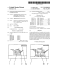
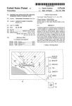
85
and/or sound (voice) or screen dumps, etc
Expert records additional comments as text
i
Expert activates (eg clicks) on a part of the
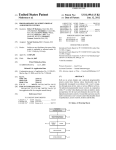
86 model to select eg service history, trends
87
Expert examines retrieved information,
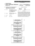
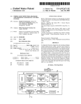
determines what problem the alarm
describes and/or which solution(s) to apply
1
88
Expert contacts operators(s) to
investigate and/or solve alarm
l
Patent Application Publication Oct. 26, 2006 Sheet 1 0f 5
Fig 1b
Fig 1a
/////\\\
1319
30 34 3233 53
Fig 2
US 2006/0241793 A1
31
3O
32
Fig 3a
33
Patent Application Publication Oct. 26, 2006 Sheet 2 0f 5
US 2006/0241793 A1
O
/
1
f01’
//
34
\
c
Fig 3b
1
.
ED:
Alarm
_
description
0
name
tlme
-
date
1
open \_
1
31
40
41
5
5
\- \.
34 34
9
Fig 36
_.
32
5e
Patent Application Publication Oct. 26, 2006 Sheet 3 0f 5
US 2006/0241793 Al
Cu:
Trend
Manual
Service hlst
Location
—'
ll
People
Electrical
Safety
Function
31
/ //
4O
Fig 6
7..
41
5b.
Patent Application Publication Oct. 26, 2006 Sheet 4 of 5
81
Alarm reported on HMI interface
of a process
82
83
US 2006/0241793 A1
-
Expert selects -go to alarm
v
l-lMl display view zooms in automatically on alarm
V
Expert activates (eg clicks) a part of the model
displayed to see a description of the alarm
84
U
Expert records additional comments as text
85
and/or sound (voice) or screen dumps,‘ etc
Expert activates (eg clicks) on a part of the
86 model to select eg service history, trends
87
Expert examines retrieved information,
determines what problem the alarm
describes and/or which solution(s) to apply
V
Expert contacts operators(s) to
88
investigate and/or solve alarm
i
‘Fig?
Patent Application Publication Oct. 26, 2006 Sheet 5 0f 5
91
US 2006/0241793 A1
Warning reported in control
system of a process
l
93
Operator selects the warning
1
95
Operator reads description of
warning in control system
96
v
Operator switches (eg clicks) to HMI and model
to see overview of all alarms and warnings
Y
97
Operator returns to control system signs
for warning and records additional
comments as text and/or sound (eg voice)
Fig 8
Oct. 26, 2006
US 2006/0241793 A1
HUMAN-MACHINE INTERFACE FOR A
CONTROL SYSTEM
CROSS-REFERENCE TO RELATED
APPLICATIONS
[0001] This application claims priority to Us. provisional
patent application 60/667,080 ?led 1 Apr. 2005.
TECHNICAL FIELD
[0002] The present invention concerns a human machine
interface for a system for control and/or monitoring of an
industrial process, automated equipment or a device. The
invention may be applied in many ?elds such as oil and gas,
electricity generation, transmission, distribution as Well as in
industry. The invention may be applied to monitoring,
control and/or programming of an industrial robot for
robotic and automated applications.
BACKGROUND ART
[0003]
A technician or a ?eld operator, eg in a process
plant, manufacturing installation, at off-shore oil and gas
platform or at an electrical poWer transmission or distribu
tion installation or substation, needs to check on alarms and
other events reported by a control system, as Well as interact
With systems or devices in the installed equipment on a daily
basis. An operator also has to have access to information and
documentation about the process(es) and the installed equip
ment. HoWever various user interfaces, both physical and
softWare interfaces, for the installed equipment, operating
devices and for one or more supervisory control systems and
so on are often designed differently so that the ?eld operators
have to learn hoW to use a multitude of different user
interfaces. The different equipment interfaces may also often
be inconsistent With respect to each other.
[0004] Us. Pat. No. 5,032,978 to Westinghouse, entitled
Status tree monitoring and display system describes a dis
play, a display method and an apparatus are disclosed Which
produce a summary display depicting function states using
discrete state bars centered in one WindoW of a tWo-WindoW
display. The display is presented to solve a problem that in
many complex processes, the operator is confronted With a
vast amount of information that must be analyZed before
appropriate action can be taken.
[0005]
The ?eld operator, as Well as interacting With
installed equipment or devices or systems, needs access to
documentation of some kind, Which may be a manual,
historical data, maintenance history & repair reports and the
like. Even though the trend is that parts of such documen
tation has become electronically available, it is often stored
in different systems and at different locations. Therefore, the
?eld operators either have to plan information gathering for
their Work tasks in advance, or they have to interrupt
ongoing tasks in order to ?nd and then access support
information and documentation for the installed equipment,
process or device. In addition, the process of obtaining
information about an alarm or about a device may take
toring and control of a process, comprising a computer
generated model of the process displaying said process or a
part or component of said process Wherein in that said model
is a 2-D or 3-D model Which is arranged to map from a point
on the computer generated model to data held by said control
system about the selected at least one part or component of
said process control an industrial automation process.
[0007] A secondary aim of the present invention is to
provide graphic information manipulate-able by an operator
to retrieve, examine and use in direct relation to a speci?c
equipment and/or device or equipment, plant or process by
means of selecting and/or activating a point on a 2-D or 3-D
model of the process, Which point is mappable via setpoints
Watchpoints or other data points to execute an instruction to
retrieve technical information. Another aim is to provide
additional information in the form of graphic information
manipulate-able by an operator to access, examine and/or
carry out control actions for a speci?c equipment, plant,
device or process.
[0008] The above and more aims are achieved according
to the invention by a human machine interface and a system
according to embodiments of the present invention.
[0009] According to a ?rst aspect of the invention, a
human machine interface of a control system for monitoring
and control of a process or equipment, comprising a com
puter generated model of the process displayed, is described.
Information, data and/or instructions for the process or a part
or component of said process are provided by manipulating
the HMI 2-D or 3-D model. Spicial points, setpoints or
Watchpoints in the model are mapped to the control system.
The operator activates or selects a device and can reteireve
technical information, send an instruction, monitor or con
?gure that device via the interface provided by the 3-D or
3-D graphic model.
[0010] According to a second aspect of the invention, a
human machine interface of a control system for monitoring
and control of a process, comprising a computer generated
model of the process displaying said process or a part or
component of said process is described for displaying the
control system information to one or more remotely located
experts for further interaction via the HMI, and for further
interaction With an original user or operator.
[0011] According to a third aspect of the invention, a
human machine interface of a control system for monitoring
and control of a process, comprising a computer generated
model of the process displaying said process or a part or
component of said process Which generated display infor
mation the operator may use to guide him/her through the
plant or process to a speci?c location of the speci?c equip
ment by means of a 2-D model of the plant or layout, and/or
by means of a 3-D model.
[0012] The general aim of this invention is to provide a
fast and ef?cient Way to locate speci?c process or equipment
control data held by a control system. The user points to the
considerable time, and may require that an operator broWses
through many databases. A considerable amount of time
valve or mixer or press on the model and is routed to the
may be necessary to search by name or system identi?cation
Online real time data, setpoints, con?guration data, service
for information about a device or process. In critical or
history, any information associated With that device by the
control system may be intuitively found and then retrieved.
emergency situations, it is very important to obtain relevant
technical information quickly to avoid material damage to
plant to process as Well as possible injury to persons in the
plant.
control system information held for that part or device.
The information obtained may be displayed to a ?eld
operator (eg an operator, a service technician, a mainte
nance person, OEM, a process engineer, etc. or to a remote
[0006] A primary aim of the present invention is to pro
person, expert, other operator etc. First of all, the HMI and
the described methods provide relevant information intu
itively and quickly to the ?eld operator for monitoring and
vide human-machine interface of a control system for moni
interaction With the industrial process or device.
SUMMARY OF THE INVENTION
Oct. 26, 2006
US 2006/0241793 A1
[0013]
The HMI and system herein is described below in
detail With respect to an oil and gas platform. The HMI
described may be used to interface With the control system
for other processes, or productions processes or automated
equipment. Brief examples in the form of scenarios for use
of the HMI Will noW be described.
[0014]
Service Team performs maintenance on platform
[0015]
Task: Service team receives assistance and guid
ance by control room operators
[0016] Industry: Oil & Gas
[0017] When the control room can visualiZe both plant and
process as a 3D model, both service personnel and control
room operators can get detailed, local information about
locations, equipment and components. This provides service
position of all personnel can reduce this stress. Furthermore,
advanced information and communication technology can
establish ef?cient multi-modal communication channels
quickly. The 3D model of the plant can also aid operators in
assisting personnel on the plant ?oor or When communicat
ing With external or remote experts. The 3D model can give
detailed information about the immediate surroundings of
the ?eld operator that needs assistance, for example by
highlighting the electric system, pipelines, valves, pumps or
other relevant components.
[0030] Production managers ensuring high process perfor
mance
[0031] Task: Identify bottlenecks and inefficiencies in
current production system
personnel With improved and more efficient guidance and
[0032] Industry: Oil & Gas
assistance from control room operators. The exact position
of the service team can be vieWed by control room operators,
and a direct communication link With document sharing,
video and sound can be used to transmit information. The
[0033] A 3D model of plant and process equipment can aid
in understanding de?ciencies or sub-optimal performance
When examining the current process. By highlighting the
equipment directly related to the process at hand, eg by
making the rest of the 3D model transparent and coding
control room operators can issue Work orders to the service
team that is closest to the equipment and the Work order can
be discussed similar to if they Were co-located. The control
room personnel can access a 3D model With graphical
representations of the service team, real-time process infor
mation, historical databases, maintenance records, proce
dure descriptions or manuals and thereby provide better
assistance and guidance to service teams.
[0018] Design and Planning an upgrade of the plant
performance levels into different colors, can be used to
understand the situation and identify bottlenecks. This is
also an ef?cient method for communicating and discussing
solutions betWeen process control engineers, control room
and ?eld operators, production managers, and other involved
parties.
[0034] Electri?cation and a planned maintenance or
upgrade of electrical system on a platform
[0019] Task: VisualiZe and simulate operation and inte
gration of neW system
[0035] Task: Plan re-routing of electrical system around
[0020] Industry: Process industry
[0036] Industry: Oil & Gas
[0021] There are often spatial constraints and compatibil
ity issues When upgrading or changing process equipment. If
the control room has access to and maintains an updated
version of a 3D model of the process and plant, this can be
used for planning an upgrade and for examining tenders. The
3D model can be examined With and Without the suggested
upgrade, and feasibility, compatibility and spatial issues can
be discussed and examined visually. Both overall compat
ibility and detail-speci?c issues can be examined by Zoom
ing/abstraction and by interacting With the virtual model.
section to be upgraded
[0037]
Control room operators and service team meet and
plan the upcoming maintenance Work on the electric system
for a section of the plant. The 3D model of the platform
displays the electric circuitry With the relevant poWer gen
erators in a (semi-) transparent vieW of the platform. The
possible re-routings can be displayed and the impact can be
examined visually for each possibility and all actors can
interact With the model to highlight important areas or
features directly. This creates a simple and unambiguous
foundation for discussion and decision-making.
[0023] Task: Improve process performance at component
[0038] Safety and a periodical safety check of all valves
[0039] Task: Control room operators perform safety check
level
of all valves
[0024] Industry: Process industry
[0040] Industry: Process industry
[0025] Access to a 3D model With advanced interaction
possibilities can help process control engineers in commu
nicating With ?eld operators, control room operators, sub
contractors and other involved parties.
[0041]
Emergency teams and a ?re on a ?oor of the plant
[0042]
Task: Assess situation and plan rescue strategy With
[0026] Operators in control room supervise ?eld operators
[0043] Industry: Process industry
[0022] Process control engineers aid ?eld operators
[0027] Task: Supervise ?eld operators, assist and issue
Work orders When necessary
emergency team
[0044]
When a ?re occurs on the plant ?oor, the ?re?ght
ers, ambulance and rescue teams need to be informed of
information such as: the exact location of the ?re and of any
[0028] Industry: Process industry
personnel, any dangerous leakages, spills or possible can
[0029] The presence of ?eld operators and other personnel
happen, and hoW to access these areas. Such information can
on the plant ?oor is often perceived as a stress factor for
control room operators. This is because the control room
be presented most ef?ciently by a 3D model of the plant,
operators do not knoW the exact position and status of these
the ?oor layout for a given production ?oor and indicates,
people and direct communication is not alWays possible. A
With for example ?ashing arroW signs overlaid on the ?oor
of the layout plan, the route to the nearest ?re exit. Such a
3D model of the plant With avatars representing the exact
and/or a 2-D model. A 2-D model that graphically visualises
Oct. 26, 2006
US 2006/0241793 A1
model provides information that may be understood even in
the stress of an emergency situation, Without any necessity
[0056]
for the vieWer to understand or even read text. The control
room, because of the HMI and because of its access to
about an axis according to another embodiment of the
technical process information, can also function as a tem
porary emergency centre Where the emergency teams can get
information and also discuss possible solutions or rescue
strategies With operators or engineers.
[0045] Authorities make a Safety inspection, eg the Rail
FIG. 6 is a display of a human machine interface
shoWing a part of the HMI display being arranged rotatable
invention;
[0057] FIG. 7 is a display of a human machine interface
shoWing operational facets of a device that are liked to data
stored in a control about the selected one or more component
parts of the process;
road Inspectorate
[0058] FIG. 8 is a schematic ?owchart for a method to
handle an alarm using the HMI to control and monitor a
[0046] Task: Authorities inspect situation at complex
process according to an embodiment of the invention;
multi-track rail stations
[0047] Industry: Railroad
[0059] FIG. 9 is a schematic ?owchart for another use of
the HMI to control and monitor a process.
[0048] When the proper railroad authorities inspect safety
DETAILED DESCRIPTION OF THE
EMBODIMENTS
and ef?ciency considerations of the railroad system, a 3D
model and/or 2-D model can be an ef?cient means for
communication and discussion. There are severe restrictions
on hoW trains can change tracks and move about on the track
system, and in large station areas the situation can be very
complex and dif?cult to grasp. A 3D model of the tracks and
[0060] FIG. 1a shoWs display of an oil platform, a process
for production or exploration etc for oil and gas. The display
1 comprises an oil platform 2, With one or more production
areas 4, and a selection menu 5a. The display in this example
is a 3-D model of an oil platform. The 3-D model displayed
is a computer generated model that may be manipulated so
trains can be used to visualiZe hoW the trains move betWeen
the tracks and to ensure all regulations are folloWed. Certain
laWs, conditions and restrictions can also be visualiZed
directly in the model, e. g. hoW much space or time must pass
betWeen tWo consecutive trains, betWeen tWo trains on
intersecting tracks, and so on. In certain circumstances 2-D
that the oil platform may be vieWed from different angles
models may also be used.
part of the oil platform. FIG. 5 shoWs schematically that the
[0049] In addition, further and advantageous aspects of the
3-d model is rotatable, for example about an axis 60 in a
direction indicated by arroW 60.
invention are described in relation to a graphical user
interface, a computer program for implementing the method
and a computer program product including the computer
program.
BRIEF DESCRIPTION OF THE DRAWINGS
[0050]
Embodiments of the invention Will noW be
and at different resolutions or magni?cations. FIG. 1b
shoWs a close up vieW of the same model of the oil platform
2, and FIG. 2 shoWs a close up of process equipment on a
[0061] The process equipment of the oil platform is moni
tored and controlled by a control system. The control system
comprises information about the process, each stage of the
process, and each separate equipment in the process. The
information, real time, historic and documentation is stored
accessible from the control system.
described, by Way of example only, With particular reference
[0062]
to the accompanying draWings in Which:
menu 5a, a tank 30, associated piping 34, a pump 33, a pump
motor 32 and a pressuriser 31. Pressuriser 31 is shoWn to be
marked in a particular Way 9 shoWn here by a dashed ring.
[0051] FIGS. 1a and 1b are a schematic representations of
a display of a human machine interface for monitoring and
controlling a process, the example shoWn being of an oil
FIG. 2 shoWs a display comprising the selection
The image of pressuriser 32 is caused to ?ash and change
colour, as suggested in the Figure by ring 9, representing by
production platform according to an embodiment of the
this feature of the 3-d model that an alarm about the
invention;
pressuriser has been logged by the control system.
[0052]
FIG. 2 is a schematic representation of a display of
a human machine interface shoWing a close up and an alarm
state according to another embodiment of the invention;
[0053] FIGS. 3a, 3b and 3c are schematic representations
of a display of a human machine interface, each diagram
shoWing a display of one or more selected layers of infor
mation according to a third embodiment of the invention;
[0054]
FIG. 4 a schematic representation of a display of
a human machine interface shoWing a display of a group of
operational or functional data selectable for a selected one or
more component parts of the process according to another
embodiment of the invention;
[0055] FIG. 5 is a display of a human machine interface
shoWing a location structure Which comprises information
[0063]
Such an alarm in a process may be handled as
folloWs. A specialist or expert on the oil platform process has
a display of the model shoWing the oil platform, as shoWn
in FIGS. 1a, lb or 6 etc. The display be a Macro vieW of the
model of the oil platform rotating, thus shoWing a ?y
around.
[0064] An alarm is signaled visually on the display and/or
by a sound signal; and the display automatically Zooms-in
through the 3D model to the speci?c device/location of the
alarm. The expert selects to vieW the alarm description
Which has been logged by the softWare of the control system,
Which is further associated With control system softWare
entities for the and each speci?c device (for example a
pop-up vieW When the expert right-clicks the image of the
device 31). FIG. 5 shoWs a display 1 Zoomed-in to the
about the physical location of a selected one or more
process equipment including pressuriser 31, and a computer
component parts of the process;
pointer device 40, a pop-up list 41 for the pressuriser. The
Oct. 26, 2006
US 2006/0241793 A1
pop up list preferably contains a description of the alarm,
title, device, nature of alarm, most recent occurrence, and so
on. A similar method of use of the HMI is shown as a
?owchart in FIG. 8.
[0065]
FIG. 3a shows a display of the process section of
for example, an overview of other active alarms and events.
After examining the other information on current events, the
operator may return to the control system 97, signs off that
he/she has noted the warning, and records text, voice or
other comments in the record for that component.
the oil platform in which process equipment pressuriser 31,
[0070]
pump 32 are shown, but the associated electrical system or
piping is not shown. FIG. 3b shows a display of the process
drawings of the plant or process. A 3-D or 2-D model may
be based in part on electrical, piping or wiring schemas or
section of the oil platform in which the piping 34 is shown,
layouts. A 3D or 2-D model is preferably layered, such that
layers of information may be added or stripped. Such layers
may represent functional groupings such as electrical sche
mas, process ?ow, physical location, utilities and services
(air, water) ?ow and so on. The model may be arranged for
but some types of process equipment are not shown. The
expert selects two additional visualisation layers each in
turn, piping 34FIG. 3b and components 31 etc in the 3-D
model. By examining the information presented about the
electrical, piping etc systems the expert can rapidly identify
what has happened to cause the alarm, and what, if anything,
ought to be done about it now or later.
[0066] FIG. 7 shows schematically a device, pressuriser
A 3-D model may be based on one or more CAD
computer control for operations such as ?y through, spin
ning, 3D viewing, Zooming. The 3-D model is somewhat
related to the computer generated virtual reality develop
ments, but applied to solving industrial problems.
31, the computer pointer marker 40, and a group of opera
tional facets stored in the control system and associated with
the pressuriser 31 that have been selected, so that the pop-up
41 is displayed. The expert selects eg right-clicks etc on
different objects such as pressuriser 31, which results in
programs by using setpoints, by monitoring watchpoints, or
activating a link or address so that associated device-relative
information such as trend curves, user manual, service
by other means. The data may be arranged based on wire
frame data constructs with or without surface rendering
history (e. g. from 800xA, a SAP, a SCADA system, physical
techniques.
location, process location, electrical schema, piping schema
etc.) is available for viewing or retrieval. The expert selects
a visualisation layer, for example People, and selects a ?eld
operator located close to the pressuriser. He opens a com
munication channel, such as by picking up a phone, and a
connection is set up automatically to the ?eld operator.
[0067]
Thus an expert or other quali?ed user may access
[0071]
Data points in the 3-D or 2-D model are associated
with devices, sensors, nodes and so on that are connected to
or otherwise controlled by one or more control systems. The
association may be arranged within one or more computer
[0072]
One or more microprocessors (or processors or
computers) comprise a central processing unit CPU per
forming the functions of the HMl and/or steps of the
methods according to one or more aspects of the invention.
This is performed with the aid of one or more computer
programs, which are stored at least in part in memory
accessible by the one or more processors. It is to be
information rapidly via the interface comprising the model.
understood that the computer programs carrying out meth
The user may as described above in relation to FIGS. 3a, b,
and 0, add a layer of information or remove a layer of
information, in order to examine the context of a device or
ods according to the invention may also be run on one or
more general purpose industrial microprocessors or com
process or of an alarm or other event from the device etc.
FIG. 8 shows in ?owchart form how a specialist or expert
may use the interface to examine an alarm and gather current
and/or historic technical information relevant to the alarm.
[0068]
FIG. 8 shows then a ?owchart wherein an alarm is
reported 81 on the display of HMI, an expert (or other user)
selects to go to 82 the alarm and the HMI can automatically
Zoom in 83 on the part of the process where the alarm has
come from. The expert can retrieve further information
about the alarm by clicking on the alarm 84. The expert can
record comments, 85 text, video clip, animation clip, voice
etc via the HMI. The expert may then access more infor
mation about the process part or device related to the alarm
puters, or on one or more specially adapted computers or
processors, FPGAs (?eld programmable gate arrays) or
ASlCs (application speci?c integrated circuits) or other
devices such as simple programmable logic devices
(SPLDs), complex programmable logic devices (CPLDs),
?eld programmable system chips (FPSCs). The computer
programs described may also be arranged in part as a
distributed application capable of running on several differ
ent computers or computer systems at more or less the same
time.
[0073] A part of the program may be stored in a processor
as above, but also in a ROM, RAM, PROM, EPROM or
EEPROM chip or similar memory means. The program in
part or in whole may also be stored locally (or centrally) on,
to obtain service history 86, trends, performance data, pro
or in, other suitable computer readable medium such as a
duction data, manuals, other documentation and so on. The
expert may then with access to any of the information in the
control system that is associated with the process alarm or
magnetic disk, CD-ROM or DVD disk, hard disk, magneto
optical memory storage means, in volatile memory, in ?ash
memory, as ?rmware, or stored on a data server. Other
device alarm make a judgement 87 and then, for example
known and suitable media, including removable memory
contact staff on site 88 or remote to investigate or otherwise
act.
media such as Sony memory stick (TM) and other remov
able ?ash memories used in digital cameras etc, phones, or
removable hard drives etc. may also be used. The program
may also in part be supplied from a data network 10, which
[0069] FIG. 9 is a ?owchart showing another use of the
HMI. An operator may switch from the process control
system to the HMI. For example as summarised, an operator
gets a warning 91 on the control system. The operator reads
the warning 95, and will obtain additional technical data.
The operator switches 96 to the HMI and model and gathers,
may in part or temporarily comprise a public network such
as the lntemet.
[0074]
In a further preferred embodiment, structured text
documents are used to link or provide references to the
Oct. 26, 2006
US 2006/0241793 A1
objects and control objects of the interface to objects and
control objects held by the control system. It is necessary to
connect 3D operator interfaces of the models to the control
system objects, such that the 3D interface can be updated
With real-time information from the process plant (eg the
3D model-part representing the object starts blinking When
the object is in an alarm situation). For this to be possible,
there must be a link betWeen the control system objects
(such as the real-time measurements from the distributed
control system) and the 3D objects. It is important to ?nd
good methods for con?guring 3D interfaces, otherWise the
engineering phase Will be much too costly because every
single control system object must be connected to a 3D
representation in addition to the 2D representation, hence to
make each link or reference by means of a manual con?gu
ration Would increase the current engineering effort to a
great extent.
[0075] Con?guring the interfaces automatically can be
done by using a structured text format (such as xml,
extended xml, caex, other industry accepted XML exten
sions) to connect the objects in a 3D model of the plant to
the corresponding objects in the control system.
[0076] This is especially advantageous for those cases
Where part of the engineering is done in CAD-programs. In
by selecting an object in the 3D or 2D interface and, for
example, choosing to “VieW live video” of this object. This
operation automatically selects the camera that can present
this object (or alternatively, the best vieW if many cameras
can vieW the object) and then manoeuvre this camera so that
the chosen object is in vieW.
[0079] For example When an operator right-clicks an
object in a process graphic he/ she can choose to “vieW object
in camera”, Which automatically presents a vieW of the
object on a monitor. This involves an automatic system for
selecting Which camera can be used to vieW the selected
object (or Which has the best vieW) and then manoeuvring
the camera (pan/tilt/Zoom) so the selected object is shoWn in
vieW. Current CCTV systems have separate HMIs (most
commonly these are separate hardWare panels) from the rest
of the control room equipment. This occupies a lot of
physical space in control rooms, is costly to develop, install
and maintain, and it is dif?cult for operators to learn and
handle many different HMIs and systems in time-critical
situations.
[0080] Traditional CCTV systems have separate HMIs
(most commonly dedicated hardWare panels) from the rest
of the control room equipment. The hardWare panels inter
faces occupy a lot of physical space in control rooms, are
these cases there is an existing 3D model of the plant. Such
costly to develop, install and maintain, and it is dif?cult for
3D model or models can either be used directly or be used
as reference for a 3D model that can be at used run-time.
operators to learn and handle many different HMIs and
Both the linkage betWeen 3D objects and control system
objects as Well as the location and orientation of each piece
of equipment can be automatically entered into the struc
tured text format from these models. Thus the information
stored in the structured text format can be populated auto
matically from engineering tools. Another advantage of use
of structured text to link 3D models to control object
information is that it reduces the time and cost of con?guring
a system. Another advantage is that manual input errors
associated With manually con?guring links to the 3D model
are eliminated.
[0077] In another preferred embodiment, controls for the
CCTV systems commonly used in some industrial installa
tions, such as oil and gas plants, may be integrated into the
systems in time-critical situations. Furthermore, the interac
tion With the cameras requires a great deal of knoWledge of
plant layout by the operator. When an operator Wants to vieW
a speci?c peace of equipment or a plant area, she must ?rst
select Which camera to use, then she must knoW the plant
good enough to guide the camera to the correct pan/tilt/Zoom
setting to get the equipment into vieW. This is often done by
a joystick-type control.
[0081]
The limited effectiveness of knoWn CCTV systems
is a similar situation to that of the knoWn audio systems.
Today, control room operators, ?eld operators, back-o?ice
personnel, remote experts and administrative personnel can
communicate orally through telephone, mobile phones,
UHF/VHF Radio systems and Public Address and Alarm
(PA & A) systems.
industrial control system. Thus it may be ef?ciently arranged
[0082] In another further preferred embodiment, such
to access a CCTV system and display pictures and video
knoWn audio system or systems in an industrial or oil and
gas installation can be connected to the control system and
images for an equipment, object or location by arranged the
CCTV system as integrated into the industrial control sys
tem. Thus by operating a control means of the human
machine interface or the 3D model described above, images
from the CCTV system of an equipment, object or location
selected via the HMI or 3D model may be displayed: and/or
CCTV or other cameras may be controlled by manipulating
the 3D representation, such that these audio systems can be
the 3D representation of the plant.
possible). Furthermore, the operator can also select directly
[0078]
In other Words, the 2D and 3D interfaces in control
rooms can also be used to control the video streams that are
already available. There are currently several sources of
video streams that are presented in the control room, and
even more that Will be available in the future. A knoWn
example is Closed Circuit TV (CCTV), Which means video
cameras that are distributed throughout the plant for sur
veillance and overvieW purposes. Another example is Wear
able cameras that the ?eld operators use in the ?eld for
improved communication With control room operators and
remote experts. These video streams can be called up to vieW
controlled by manipulating the 3D representation of the
plant. Examples of such use can be to automatically dial a
?eld operator by clicking on the avatar or symbol represent
ing the operator in the 3D or 2D interface (and also selecting
the preferred communication means if more than one is
in the 3D interface Which areas to dispatch a message over
the PA & A system to. This can be very effective and
poWerful When combined With a 3D representation of a gas
leakage, for example.
[0083] In such a situation, information about Which gas
detectors have gone into alarm state combined With knoWl
edge of escape routes and possibly also metrological infor
mation can be used to select Which areas should be noti?ed
With the alarm Warning message. An advantage of generat
ing this information from other (non audio) information
accessed by the HMI or 3D model is that an operator may
Oct. 26, 2006
US 2006/0241793 A1
activate communications such as UHF/VHF transmissions
or loudspeaker announcements for selected areas of the plant
by the alarm or event affected Without having to have
extensive or detailed location knowledge beforehand.
[0084] It should be noted that While the above describes
exemplifying embodiments of the invention, there are sev
eral variations and modi?cations Which may be made to the
disclosed solution Without departing from the scope of the
present invention as de?ned in the appended claims.
1. A human-machine interface of a control system for
monitoring and control of a process, comprising:
a computer generated model of said process displaying
said process or a part or component of said process,
Wherein said model is arranged to map a point on the
computer generated model to data held by said control
system about the at least one part or component of said
process.
2. An The interface according to claim 1, Wherein said
model is arranged for manipulation by computer softWare
means to change the shape of the displayed image and
generate a change in an orientation of one or more selected
parts of said model so displayed.
3. The interface according to claim 1, Wherein said model
is arranged for manipulation by computer softWare means to
change the shape of the displayed image so and rotate said
computer softWare means for displaying technical informa
tion relevant to a selected function, location or other opera
tional facet of the one or more parts of said process.
12. The interface according to claim 11, Wherein the one
or more graphic components of said model are arranged With
computer softWare means for displaying technical informa
tion relevant to a selected one or more components grouped
into a plurality of functions, locations, and/or operational
facets for the selected one or more parts of said process.
13. The interface according to claim 1, Wherein said
model is arranged displayed at least in part as a tWo
dimensional representation of said process, arranged for
manipulation by computer softWare means to so as to
graphically change an orientation of one or more selected
parts of said model.
14. The interface according to claim 1, Wherein said
model is arranged displayed at least in part as a three
dimensional representation of said process, arranged for
manipulation by computer softWare means to so as to
graphically change an orientation of one or more selected
parts of said model.
15. The interface according to claim 13, Wherein said
model is arranged for manipulation by computer softWare
means to so as to graphically change both scale and orien
tation of one or more selected parts of said model.
model or selected parts of said model about at least one axis.
16. The interface according to claim 15, Wherein said
model is arranged so as to graphically change both scale and
4. The interface according to claim 1, Wherein said model
orientation of one or more selected parts of said model at the
is arranged for manipulation by computer software means to
change the shape of the displayed image and change the
same time.
scale of the one or more parts of said model so displayed.
model is arranged so as to change both one or more selected
5. The interface according to claim 1, Wherein said model
is arranged changeable With computer softWare means to
present a visual display comprising a Zoom-in on, and/or
parts of said model and display a moving image of said
model in a mode of any from the list of: ?y through,
Zoom-out from, one or more parts of said model so dis
17. The interface according to claim 15, Wherein said
spinning, 3D vieWing, Zooming.
18. The interface according to claim 1, Wherein said
played.
model is arranged for manipulation by computer softWare
6. The interface according to claim 1, Wherein said model
is arranged With computer softWare means to display, shoW
means to superimpose a layer of information on top of the
shape of one or more selected parts of said model.
or superimpose technical data or information from any part
of said process on the display of the one or more parts of said
model is arranged for manipulation by computer softWare
model.
7. The interface according to claim 6, Wherein said model
is arranged With computer softWare means to provide an
active link for accessing or retrieving technical data or
means to remove a layer of information from the shape of
one or more selected parts of said model and display other
information about said process.
20. A method to monitor and control a process using a
information about any of the one or more selected parts or
human-machine interface for a system for monitoring and
components of said process displayed by said model.
control, the method comprising:
8. The interface according to claim 1, Wherein said model
is arranged With computer softWare means to provide an
active link for accessing or retrieving technical data or real
19. The interface according to claim 1, Wherein said
producing a model of said process With at least one
graphic element displaying one or more parts or com
ponents of said process,
time information about a technical function of one or more
selected parts or components of said process.
9. The interface according to claim 1, Wherein said model
is arranged With computer softWare means to provide an
active link for accessing or retrieving historical technical
selecting a point on the model, and
mapping the point or data point on the computer gener
ated model to data held by said control system about the
at least one part or component of said process.
data or information about a technical function of one or more
selected parts or components of said process so displayed.
10. The interface according to claim 8, Wherein one or
more graphic components of said model are arranged With
computer softWare means for displaying a plurality of
groups of technical information grouped relevant to a
selected function, location or other operational facet or of a
selected graphic component.
11. The interface according to claim 1, Wherein the one or
more graphic components of said model are arranged With
21. The method according to claim 20, further compris
mg:
retrieving technical information associated With a device
or process displayed or represented by said graphic
element and
presenting the information on the display.
22. The method according to claim 20, further compris
ing:
Oct. 26, 2006
US 2006/0241793 A1
presenting for selection a group of information structures
holding operational data about different facets of the at
least one part or component of said process.
23. The method according to claim 20, further compris
mg:
presenting for selection a list of information sources
structures holding real time or historic operational data
a computer generated model of said process displaying
said process or a part or component of said process, and
a computer comprising a Human Machine Interface com
prising a model of said process arranged in that said
model is arranged to map a point on the computer
generated model to data held by said control system
about the at least one part or component of said process.
about different facets of the at least one part or com
34. The control system according to claim 33, Wherein the
ponent of said process.
24. The method according to claim 20, further compris
human-machine interface comprises a model of said process
arranged to map knoWn set points in the model to data held
by said control system about the at least one part or
component of said process.
mg:
presenting on the display information of a Warning or
alarm that has occurred in respect of the at least one
part or component of said process.
25. The method according to claim 20, further compris
mg:
35. The control system according to claim 33, Wherein the
human-machine interface may be displayed and/ or manipu
lated using a portable and/or Wearable computing device.
36. The control system according to claim 33, Wherein the
knoWn set points in the model are linked or referenced to
presenting on the display selection means (5) to receive
data held by said control system about the at least one part
and or go to the Warning or alarm that has occurred in
respect of the at least one part or component of said
process.
or component of said process by means of one or more
26. The method according to claim 20, further compris
mg:
manipulating the model to automatically go to the at least
one part or component of said process for Which the
Warning or alarm has been signalled.
27. The method according to claim 20, further compris
mg:
manipulating the model to automatically go to the at least
one part or component of said process for Which the
Warning or alarm has been signalled.
28. The method according to claim 20, further compris
structured text documents.
37. The control system according to claim 33, Wherein the
structured text documents link control system objects to 3D
model representations and their physical position/orienta
tion.
38. The control system according to claim 36, Wherein at
least one structured text document is generated automati
cally.
39. The control system according to claim 33, further
comprising
means for selection of a part of a human-machine inter
face or 3D object and to display one or more visual or
video images of a selected object.
40. The control system according to claim 39, further
comprising
mg:
manipulating the model to add or remove a layer of
operational information associated With the at least one
part or component of said process for Which the Wam
ing or alarm has been signalled.
29. The method according to claim 28, further compris
means for control of the video images from the control
system.
41. The control system according to claim 33, further
comprising
means for access to oral communication means With an
mg:
operator by selecting a symbol of the a human-machine
manipulating the model to add or remove a layer of
operational information associated With the at least one
part or component for any from the list of: electrical
system, Water/utility system, location of people,
alarms, process materials, ?re and/or gas leakages
30. The method according to claim 28, further compris
mg:
manipulating the model to display the at least one part or
component by means of any graphic operation or 3D
modeling operation from the list of: ?y through, spin
ning, 3D vieWing, Zooming.
31. A computer program Which When read into a computer
or processor Will cause the computer or processor to carry
out a method according to the steps of claim 20.
32. A computer readable medium comprising
a computer program Which When read into a computer or
processor Will cause the computer or processor to carry
out a method according to the steps of claim 1.
33. A control system comprising a human-machine inter
face of a control system for monitoring and control of a
process, comprising
interface or a 3D model control system.
42. The control system according to claim 41, further
comprising
means for access to oral or audio communication means
in a given area of an installation by selecting or
manipulating a symbol of the a human-machine inter
face or 3D model control system.
43. A human-machine interface of a control system for
monitoring and control of a process, comprising
a computer generated model of said process displaying
said process or a part or component of said process,
Wherein said model is a 3-D model arranged to map a
point on the computer generated model to data held by
said control system about the at least one part or
component of said process.
44. Use of a human-machine interface of a control system
for monitoring and control of a process, comprising a
computer generated model of said process displaying said
process or a part or component of said process, for providing
and presenting information in a control system of an oil or
gas storage, treatment or process installation.
Oct. 26, 2006
US 2006/0241793 A1
45. Use of a human-machine interface of a control system
for monitoring and control of a process, comprising a
47. The control system according to claim 41, Wherein the
means for access to oral communication means With an
computer generated model of said process displaying said
operator comprises a UHF/VHF radio or phone or portable
process or a part or component of said process, for providing
and presenting information in a control system of an elec
trical generation, transmission or distribution installation.
phone.
46. The control system according to claim 40, Wherein the
means for control of the Video images from the control
48. The control system according to claim 42, Wherein the
means for access to oral or audio communication means
comprises oral or audio means, Public Alarm & Address
devices, and/or loudspeakers.
system comprises means to remotely operate pan/tilt/Zoom
controls of a camera.
*
*
*
*
*