1
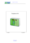
Temptron 616 User's Manual
INSTALLATION
Open the front panel
1. Connect the Temptron 616 to the wall in a dry place approximately 1 meter away
from the electrical cabinet.
2. Connect the Temperature Sensors to the sensor inputs.
The sensors can be placed up to 100 meter from the main unit with an ordinary twowire cable. The sensor has no polarity.
3. Connect the relay outputs to the various systems. All outputs are dry contacts,
maximum 2 Amp/220V NO/NC.
4. Connect a dry contact from flap 1 to the digital 1 input.
Connect a dry contact from flap 2 to the digital 2 input.
Connect a dry contact from the feed contactor to the digital 7 input.
Connect a dry contact from the water clock to the digital 8 input.
6. Connect a 220V cable to the unit.
7. Close the panel with the two screws.
OPERATION
The Temptron 616 will display the average temperature of the connected temperature
Sensors. It is possible to display each sensor separately.
Turn on power.
1. Each time power is connected to the unit “Agro Lo” will appear on the display.
The Temptron 616 is calibrating its connected sensors.
2. After 20 Seconds the average temperature will appear on the left display.
3. To display sensor 1, press on button “1”.
The temperature of Sensor 1 will be displayed.
4. To display Sensor 2, press on button “2”.
The temperature of sensor 2 will be displayed.
READING SET POINT
It is possible to read all the information on the Temptron 616 display.
The right display indicates the function number. The left display shows the set point
for each function.
Each set point has a code number (see menu on the front panel). It is possible to go
into the code in two ways:
1. By pressing on the “DATA” button the code number display on the right side of
the panel will increase. The preset information will appear on the data display on the
left side of the panel.
2. By pressing on the “0” button, two lines will appear on the code display and
“FUNC” on the data display.
Page
3