1
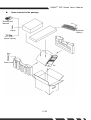
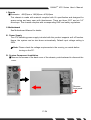
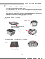
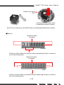
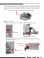
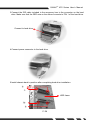
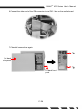
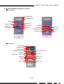
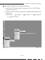
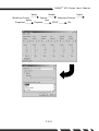
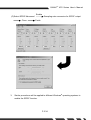
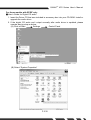
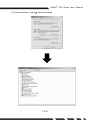
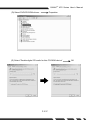
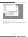
G-MAX TM ATX Series User’s Manual Copyright Notice Copyright 2001 Gigabyte Technology. All Rights Reserved. No part of this documentation, including but not limited to the products and software described in it, may be reproduced, transmitted, transcribed, stored in a retrieval system, or translated into any language, in any form or by any means without the express written permission of Gigabyte Technology. Trademarks Products and corporate names appearing in this manual may be registered trademarks or copyrights of their respective companies and are used only for identification or explanation purposes without intent to infringe. Other product names used in this manual may be trademarks or registered trademarks of their respective owners. The author assumes no responsibility for any errors or omissions that may appear in this document nor does the author make a commitment to update the information contained herein. Third-party brands and names are the property of their respective owners. Disclaimer The information contained in this documentation is subject to change without notice. Gigabyte Technology makes no representations or warranties of any kind, either express or implied, with respect to the contents hereof, including but not limited to implied warranties of merchantability or fitness for a particular purpose. In no event shall Gigabyte Technology. Be liable for any loss of profits, loss of business, loss of data, interruption of business, or indirect, special, incidental, or consequential damages of any kind arising from the use of this product or documentation. Gigabyte Technology reserves the right to revise or change this product or documentation at any time without obligation of Gigabyte Technology. To notify any person of such revision or changes. Aug/2002 P. E1 G-MAX TM ATX Series User’s Manual Preface This system unit is designed to be stable, safe, and easy to use. The system can be upgraded and expanded in function easily if correct procedure is followed. For your own safety and to avoid accidental damage to your system, please ensure you follow the following precautions: Follow all the warnings and instructions marked on the products. To remove or clean the product, remember to unplug the power cord. Place your system unit in a cool, clean space, to be far away from water, heat and dust. Before connecting any peripheral equipment, please unplug the power cord from the system unit to prevent unexpected damage. The AC input supplies power to the system unit. Check your dealer if you can not recognize the type of the power supply. CAUTION Danger of explosion if battery is incorrectly replaced. Replace only with the same or equivalent type recommended by the manufacture. Dispose of used batteries according to the manufacturer’s instructions. Introduction TM G-MAX series product, to adopt main board of design & development by GIGABYTE that is ATX mechanical design in advance, let you work smoothly in Windows environment. ATX adopts dexterous mechanical design, so it is ease by assembly & safeguard. Specification Overview ATX chassis ATX main board of GIGABYTE Power supply DVD-ROM / CD-ROM / CD-RW (Option) 1.44 “FDD Multi I/O Card (Option) Keyboard (Option) Assembly Box Content Main board user’s manual User’s manual Main board Driver CD IDE cable Screw bag Mouse (Option) SPDIF cable (Option) P. E2 G-MAX TM ATX Series User’s Manual Items included in the package Software and Manuals Keyboard (Option) Cables Mouse (Option) Power Cord PC P. E3 G-MAX TM ATX Series User’s Manual I. Chassis ŜDimension 460(D)mm x 186(W)mm x 430(H)mm This chassis is made with material complied with UL specification and designed for space saving and easy open with thumbscrew. There are three 5.25” and six 3.5” drive bays. This chassis complies with corresponding EMC and safety regulations. II. Motherboard See Motherboard Manual for details. III. Power Supply The ATX switching power supply included with this product supports soft off function. Hence, the system can be shut down automatically. Default input voltage setting is 230V. Note: Please check the voltage requirements in the country you reside before turning on the PC. IV. System Component Installation ŜRemove the screws of the back cover of the chassis, push backward to dismount the cover. Remove front panel P. E4 G-MAX TM ATX Series User’s Manual ŜCPU 1. Insert the CPU on the CPU socket. Before installation, lift up the lever and align the cut of the CPU with the marking on the socket. 2. Pull down the lever to lock the CPU on the socket after installation. When you are installing the heat sink, please make sure to keep the heat sink tight against the CPU to obtain the best cooling result. 3. Apply the thermal compound to one side of the template, and ensure the compound is spread evenly across the template and repeat if necessary. 4. Connect fan power connector to the CPU FAN connector on the motherboard. A. For Intel Pentium 4 processors CPU Pin Lever Apply thermal grease to the top of the CPU properly. Click the heat sink locker to the motherboard retention module. Install fan on top of CPU B. For AMD Athlon TM TM and AMD Duron processors Lever CPU Pin Apply thermal grease to the top of the CPU properly. P. E5 G-MAX TM ATX Series User’s Manual Install fan on top of CPU Click the heat sink locker to the motherboard retention module. Set CPU clock frequency from BIOS Setup, see Motherboard Manual for details. ŜMemory Notches at sides of module SDRAM Position notches. Make sure that the notches should align the pin on memory slot on the motherboard Notches at sides of module DDR Position notches. Make sure that the notches should align the pin on memory slot on the motherboard P. E6 G-MAX TM ATX Series User’s Manual In this section we will guide you to install memory module. First, make sure the position notches at the bottom of the module should align to the pins on the module sockets on the motherboard, then push the module downward until the locks hook up notches at sides. Locks: make sure they hook up the notches at sides of module ŜHard Drive Installation 1.Remove 4 screws in front of the hard drive chassis and dismount chassis. HDD frame Press down splinter then pull out HDD frame. 2.The chassis accommodates up to six 3.5” storage devices. Select a place and fix the hard drive with screws. 3.5” floppy Drive HDD Drive HDD frame P. E7 G-MAX TM ATX Series User’s Manual 3.Connect the IDE cable included in the accessory box to the connector on the hard drive. Make sure that the RED wire on the ribbon connects to PIN 1 of the hard drive. Connect to hard drive 4.Connect power connector to the hard drive. 5.Install chassis back to position after completing hard drive installation. HDD frame P. E8 G-MAX TM ATX Series User’s Manual 6.Connect the other end of the IDE connector to the IDE-1 bus on the motherboard. 7.Check all connections again. Put back side panel Put back front panel P. E9 G-MAX TM ATX Series User’s Manual V.System Installation and User’s Guide ŜFront Panel CD ROM Tray CD-ROM Button Floppy Power LED Floppy LED Power Button Floppy Drive Eject Button *SPDIF 1394 Hub Audio Out PCMCIA Button USB Port HDD LED PCMCIA Port ŜRear Panel Power Inlet Voltage Switch Power Switch Mouse Port (PS/2) Keyboard Port (PS/2) COM Port LPT Port *COM Port / VGA Port Audio Out Game Port Audio In LAN Port MIC In USB Port 1394 Port P. E10 MIC In G-MAX TM ATX Series User’s Manual ŜNote 1.To avoid breaking disc during high-speed operation, we recommend you to use high quality CD/ Recordable CD/ Re-writable CD. 2.Specification with “Ŏ” mark are subject to change without notice. 3.For latest drivers update, please visit our Web site listed below: http://www.gigabyte.com.tw/products/plat_index.htm ŜImportant Safety Instructions Caution –To reduce the risk of fire, use only No.26 AWG or larger telephone line cord. Caution –Always disconnect all telephone lines from the wall outlet before servicing or disassembly this equipment. Caution –Danger of explosion if battery is incorrectly replaced. Replace only with the same or equivalent type recommended by the manufacturer. Dispose used batteries according to the manufacturer’s instructions. P. E11 G-MAX TM ATX Series User’s Manual ▓User’s Guide for SPDIF (For those models with SPDIF only) 1. Insert the Driver CD that was included in accessory box into your CD-ROM. Install or upgrade the audio driver. 2. If SPDIF can’t output normally after audio driver is updated, please operate step by step as below. (A)Click on Start Programs Volume Control P. E12 Accessories Entertainment G-MAX Select (B)Volume Control Select Properties TM ATX Series User’s Manual Enable Options Add Playback P. E13 Select Advanced Controls SPDIF OK G-MAX (C)Select SPDIF Advanced Close 3. Enable TM ATX Series User’s Manual Sampling rate conversion for SPDIF output Finish ® Similar procedures will be applied to different Windows operating systems to enable the SPDIF function. P. E14 G-MAX TM ATX Series User’s Manual For those models with SPDIF only ▓User’s Guide for Digital CD audio 1. Insert the Driver CD that was included in accessory box into your CD-ROM. Install or upgrade the audio driver. 2. If the digital CD audio can’t output normally after audio driver is updated, please operate step by step as below. (A) Click on Start Settings Control Panel (B) Select “System Properties” P. E15 G-MAX (C) Select Hardware Device Manager P. E16 TM ATX Series User’s Manual G-MAX (D) Select DVD/CD-ROM drivers TM ATX Series User’s Manual Properties (E) Select ”Enable digital CD audio for this CD-ROM device” P. E17 OK G-MAX TM ATX Series User’s Manual (F) Select “YES” ® 3. The “Enable digital CD audio for this CD-ROM device” option in Windows ME and ® Windows XP is default set to “Enable”. ® 4. Similar procedures will be applied to different Windows operating systems to enable the digital CD audio function. P. E18