1
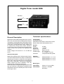
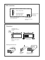
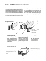
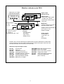
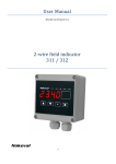
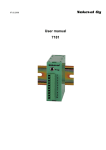
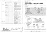
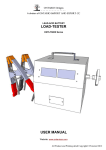
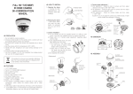
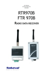
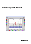
Nokeval
No 11198
User's manual
Timer 2066
1
Contents
General Description .................................................................................. 3
Indicator family 2000 .................................................................................................. 3
Technical specifications: ......................................................................... 3
2066 connections ...................................................................................... 4
Dimensions ................................................................................................ 4
Series 2000Panelmeter construction ...................................................... 5
Change of meter type: ............................................................................................... 5
Additional slots: .......................................................................................................... 5
Power supply: ............................................................................................................. 5
2000 series input and option cards: ......................................................................... 6
Modular indicator serie 2000 .................................................................... 6
Manufacturer:
Nokeval Oy
Yrittäjäkatu 12
FIN-37100 NOKIA
FINLAND
Tel
+358 (0)3 342 4800
Fax. +358 (0)3 342 2066
email [email protected]
2
Digital Timer model 2066
Start/Stop
Reset
Technical specifications:
General Description
Timer display
99.59.59 (h/min/s):
Start/Stop contact starts or stops timer function
Reset contact resets the display 00.00.00
Digital panel meter 2066 is designed for time counter,
timer. Unit counts seconds into display after start input
is activated. Counting starts with closing Start contact
and ends with opening Stop contact. Counting can be
continued by closing Start button again. Display can
be resetted with closing Reset contact. Maximum
counted time is 99 hours 59 minutes and 59 seconds.
Hours, minutes and seconds are separated with
commas.
Supply voltage is 90..240 VAC or 12...32 VDC (24
VAC).
General:
Display
Resolution
Digit height
Display color
Powers supply
Protection
Indicator family 2000
Optional:
Field housing
Digital Timer 2066 is a part of a larger product family.
This series 2000 indicators are easy to modificate for
different type of inputs e.g. 2066 can be changed for
BCD-/ Grey-code input input simply by changeing the
input card to type 2081. This kind of modification
doesn't require any kind of calibration, user only
configures the unit with front panel keys.
When input card is changed it changes also the model
type. e.g. if this timer, model 2066 is modified for serial
data indicator with 2071-RS485 input card, the model
will change to 2071.
6 Digits
1 second
14.5 mm
Bright red LED
90...240 VAC or
12...32 VDC or 24 VAC
Front panel P65 with gasket
Model 2000IP65-1 for 1 unit
Model 2000IP65-2 for 2 unit
Model 2000IP65-3 for 3 unit
Model Types:
2066-24VDC
2066-230VAC
3
Power 24 V (12-32 VDC)
Power 85...240VDAC
No Polarity
2066 connections
Contacts
6
5
4
3
2
1
Slot A
Reset, closing contact
Start /Stop terminals 2-3
Close contact =Start
Open contact =Stop
Slot A is for input card, slots B
and C for optional cards.
Terminal colour codes:
Grey 230 VAC
Green 24 VDC
7 8 9
Power 90...230 VAC
or 12.....32 VDC, 24 VAC
No Polarity
Dimensions
Install guides on the
corners helps centralizing
the case.
ø2,0
105
48
96
6
Cutoff
43.5 (H) x 90.5 (W) mm
± 0,5 mm
10
Gasket (IP65)
Removing unit from its case
Paina ja vedä
A
Detachable
connectors
2,5 mm²
4
B
C
Model 2066 accepts
only Slot A usage
Series 2000 Panelmeter construction
The 2000 series panelmeters are modular and easy to
assemble. According to customers wishes. The basic
construction consists of mother board with tree slots,
A, B and C. Slot A determines meter type and provides
always input signal. Slot B and C are interchangeable.
As factory delivery input signal is always installed into
slot A , mA output into slot B and alarms into slot C. In
case of f.ex 4 alarms and relay card with 2 changeover contact (2 + 2 relays) are used, you must place
second relay card into slot B. If you accept only closing
or opening relay contacts, you need only one relay
card with 4 relays placed into slot C. The slot B is now
usable for other optional outputs.
You can have different types of meters by only
changing the input card in slot A. Data sheet of each
type of meter dictates the possible combinations.
Recalibration of card is not needed; only scaling and
other settings must be set by front panel keys.
All cards have calibration
memory
Slots A-C
A
B
C
Power supply 11. .32 VDC
(Green connector)
or 85...240 VAC
(Grey connector)
Change of meter type:
Input card is placed always to
slot A. By changing input card
you can get an other type of
meter. You can change meter
with pulse input to meter with
current input, thermocouple,
strain gage etc.
Additional slots:
Additional cards provide output
4..20 mA, alarms, serial
interface, BCD output etc. Meter
data sheet dictates possible
combinations. grey connectors
allow line voltage 110...230 VAC
(relay contacts).
Power supply:
There are two different
mother boards power supply
85..230VAC and 12...32
VDC. VDC-mother board
accepts also 24 VAC.
Connectors are colour
coded.
Removing meter from case:
Press gently case behind front panel
and draw frame outwards gripping
upper part of frame.
Loose connectors and fastening screw
beside power connector. Loose front
panel and draw meter out from front.
You may remove mother board from
rear by opening four screws in corners
of case
5
Modular indicator serie 2000
5 digit (2011) or 6-digit
bright red LED display
Option cards
(slots B and C):
E²
6543.21
Alarms cards:
2 relay card, 4 alarm types,
change over contacts
3 relay card, closing contacts
4 I/O-ports
E²
DAC
Sensor supply:
24VDC,
150 mA
2021
E²
2011
E²
ADC
Process inputs (model 2011):
0..20 mA, 4..20 mA
0..1V/5/10 V
Potentiometer 100Ω-10 kΩ
uP
Model 2011:
2 relays change over contacts
(also with remote reset)
Output cards (not for 2011):
0/4..20 mA, 0..10 V
RS232 or RS485
Input card
contains:
- microprocessor
- bus control
- keys control
- display control
Power supply:
85..260VAC or
12..32 VDC / 24
VAC
No Polarity
Indicator 2011 can have limited part of 2000 series functions. Model 2021 contains also
process inputs but it can also measure RTD-sensors and thermocouples. 2021 has more
accurate and faster A/D-converter (16 bit 1/64 000).
2000 series input and option cards:
2011-IN
2021-MU
2031-IR
2041-STG
2051-Hz
2061-CNT
2071-RS
2081-BCD
2000-BASE
2000-REL2
2000-REL3
2000-OUT
2000-RS
2000-I/O
Process input
Multi input
Infrared sensor input
Strain gage measurement
Scaleable frequency indicator
Counter input (max 5 kHz)
Serial input RS232 / RS485
BCD-input (1-5 digits)
6
Base card with power supply
Alarm card, NO/NC
Alarm card, Closing contacts
Output card, U and I
Serial output RS232 or RS485
4 pcs input /output ports
(60 V / 100 mA)
7
Manufacturer:
Nokeval Oy
Yrittäjäkatu 12
FIN-37100 NOKIA
FINLAND
Tel
+358 (0)3 342 4800
Fax. +358 (0)3 342 2066
email [email protected]
8