1
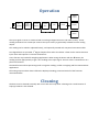
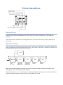
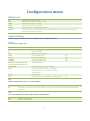
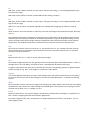
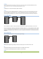
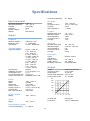
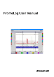
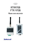
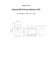
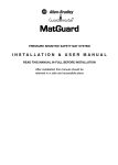
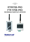
User Manual 2011-02-21, firmware V1.1 2-wire field indicator 311 / 312 Nokeval 1 Introduction The field display 311 is a versatile instrument combining a two wire 4-20 mA transmitter and an LED display accepting almost all common sensor inputs. It can be powered with a 10…30 VDC supply if an analog output is not needed. The galvanic isolation provided is especially important with thermocouples, but helps to avoid potential differences in other applications too. The device can be configured with the front panel buttons. The device is housed in a splash proof wallmounted enclosure. The model 312 is equipped with two semiconductor relay alarm outputs. The relays are rated for 250 VAC. Warnings Although the input circuitry is galvanically isolated, the isolation is purely functional and intended to prevent the problems associated with ground loops and potential differences. The input signal must not be connected to a voltage higher than 120 VDC or 50 VAC with respect to earth. When using a line voltage with the alarm relays, the associated wires must be tied so that they can’t come in contact with the other parts inside the unit in case of accidentally detaching from the connector. Trademarks Exergen is a registered trademark of Exergen Corporation, USA. Manufacturer Nokeval Oy Yrittäjäkatu 12 FI-37100 Nokia Finland tel:+35833424800 2 Installing Connections The connector blocks are detachable. Alm 1 Alm 2 Thermocouples 1 2 3 4 1 2 3 4 5 6 + - 311 / 312 1 2 3 4 5 6 Pt100 3- or 4-wire ( ) 7 8 9 mA input + TC&mV + Input (-) + 0-5/10V 0/4-20 mA 1 2 3 4 5 6 (-) (+) 24 VDC Power supply Pt100 - 1 2 3 4 5 6 (Com) + 0/4-20 mA Jumpers There are no user-configurable jumpers. Configuration Using the front panel keys This device can be fully configured using the front panel keys. Using the keys is described in chapter The device can be cleaned externally with a soft cloth and soap water. Cleaning with a small amount of isopropyl alcohol is also allowed. User interface. The settings are explained in chapter Configuration menu. With a configuration software Using a configuration cable POL-RS232 or DCS772 and an adapter POL-3PIN, Nokeval Mekuwin configuration software can be used for convenient configuration. This is especially useful when configuring large number of devices as the settings may be saved to a file and then retrieved. The settings are explained in chapter Configuration menu. There is a pin header marked as POL on the circuit board. Connect the adapter cable to this. Start the software and select 9600 baud and the appropriate COM port. Use address 0 or 126. 3 Operation Analog output A/D converter Input lineariz & scaling Custom lineariz Lopass Slew Tare Dead Display Sensor Alarms The input signal or sensor is measured with an analog-to-digital converter and other circuitry. A new reading is obtained 3 to 4 times per second. The input circuitry is galvanically isolated from the analog output. The reading can be scaled or adjusted linearly, and optionally treated with a 6-point linearization table. Two digital filters are provided: 1st degree lowpass filter and a slew limiter. These can be used to decrease input noise and response to transient fluctuations. A tare function is provided for weighing applications. When taring the device with the * button, the reading is offset appropriately to get a zero reading at this input signal. The tare value is retained even in a power-off situation. The Dead function allows preventing small or negative readings, useful in weighing and flow measurement applications. The analog output and the alarms follow the displayed reading, processed with all of the functions mentioned above. Cleaning The device can be cleaned externally with a soft cloth and soap water. Cleaning with a small amount of isopropyl alcohol is also allowed. 4 User interface Config state LED Maximum memory Minimum memory Alarm indicators Nokeval Conf 5620 * Select Exit Enter; operator menu Unit label Normal state In normal state, this device displays the current measurement value continuously functioning as an indicator. The A1 and A2 LEDs indicate the current state of the alarms. The device is in this state after power-up. If the tare function is enabled in the configuration menu, you can tare the unit by pressing the * key for one second. Operator menu The alarm levels and the minimum/maximum memory can be accessed without entering the configuration state. Use the > key to select function (Alarm level 1 – Alarm level 2 – Minimum – Maximum – Normal); the blinking indicator LEDs indicate the current function. + Conf Normal Normal state Tare + Conf Al 1 Alarm level 1 Reset hold Edit level Al 2 Alarm level 2 Reset hold Edit level Min Max Minimum Reset Maximum Reset When an alarm LED is blinking, the alarm level can be changed. Press ▲ or ▼ until the first digit starts blinking, then edit as described in chapter Editing. When an alarm (A1 or A2) or minimum (M1) or maximum (M2) LED is blinking, the associated alarm hold or minimum/maximum memory can be reset by pressing * for one second. 5 If a password has been set (Alcode in configuration menu), the alarm levels can’t be changed nor functions reset without entering the correct password. Configuration state Press ▲ and * simultaneously for two seconds to enter the configuration state. When entered, the Conf LED will light. Conf menu + Item 1 If a configuration password is set, you will need to enter it now (Cod.0 displayed). In case the password is not known, switch the power off, hold * and > keys pressed and switch the power on again. Edit value Item 2 Edit value Save Submenu Item 3 Undo The first item of the main level of the configuration menu is shown: In. Move within the menu using ▲▼ keys. Enter a submenu with >. To edit the value of a setting, push > to start editing. Use ^v> to edit, and * to get back to the menu. Item 3.1 Edit value Item 3.2 The menu is organized hierarchically. You can enter Out, Alm1, Alm2, and Lin submenus by selecting them with ▲▼ keys, and entering the submenu with the > key. See the menu chart. When all settings are done, exit from the menu with * key. Two options are shown: save to keep the settings made, and undo, to discard all changes. Select Save or Undo and push >. The contents of the configuration state are detailed in the chapter Configuration menu. A quick overview is shown below. The items on the shaded background are hidden in certain cases. In Sensor Conf In Bip Out Out Alm1 Lo Alm2 Cfcode Alcode Hi Config password Operator password Mode Break Analog output Low end scaling High end scaling Limited/overranging Fault indication 4W Lo Hi Emis R0 Unit Dec Lopass Slew Alm1/2 Type Level Hyst Alarms (model 312) Low or high alarm Alarm activation level Hysteresis 6 Dead Pullup Lin Tare Input Input/sensor type Bipolar measurement on mV/V/mA Off = 3-wire connection, On = 4-wire Low end scaling or offset High end scaling Emissivity/slope correction on tc’s Nominal resistance of an RTD Temperature unit °C or °F Displayed decimals Low pass filter, time constant in secs Slew rate limiter, 0 = disabled Dead zone, -1 = disabled Sensor break detection Submenu for linearization table Enable the tare function Configuration menu Main level In Out Alm1 Alm2 Cfcode Alcode Submenu for input settings. Submenu for analog output settings. Submenu for alarm 1 settings. Submenu for alarm 2 settings. Password for the configuration menu. Password for the operator menu (quick editing the alarm values and resetting the minimum/maximum memory). Input settings These settings are located in the In submenu of the configuration menu. Sensor Input sensor or signal type. Selection mV V mA 0-5V 0-10V 0-20mA 4-20mA TcB, TcC, TcD, TcE, TcG, TcJ, TcK, TcL, TcN, TcR, TcS, TcT E140, E440 Ohm Pt, Ni Pot Explanation Millivolts up to 100 mV Volts up to 10 V Milliamps up to 20 mA 0-5 V scaled input 0-10 V scaled input 0-20 mA scaled input 4-20 mA scaled input Thermocouples Exergen infrared thermocouples Resistance measurement , including a potentiometer in a variable resistance configuration RTD sensors Potentiometer in a “slidewire” configuration Lo-Hi scaling Yes Yes Yes Yes Yes Bip Bipolar measurement on mV, V, and mA signals. Off On The device can’t measure below 0 V nor 0 mA The device can measure down to -100 mV, -10 V, and -20 mA, but with slightly diminished resolution. 4W Four-wire connection on RTD’s and resistance measurement. Off On 3-wire measurement 4-wire measurement 7 Lo With 0-5V, 0-10V, 0-20mA, 4-20mA, and Pot inputs: The low end scaling, i.e. the reading displayed on the low end of the range. With other inputs: Offset correction, will be added to the reading. Usually 0. Hi With 0-5V, 0-10V, 0-20mA, 4-20mA, and Pot inputs: The high end scaling, i.e. the reading displayed on the high end of the range. With mV, V, mA, and ohm: A multiplier applied to the reading before applying the offset (Lo setting). Emis Slope correction for thermocouples or emissivity correction for Exergen infrared thermocouples. Normally set to 1. The temperature difference between the measured sensor temperature and the ambient temperature is divided by the Emis setting and added to the ambient temperature to get the displayed reading. In other words, the slope of the thermocouple reading is amplified by 1/Emis when distancing from the ambient temperature. The ambient temperature is obtained from the internal cold junction compensation. R0 The nominal resistance of the Pt or Ni sensor, i.e. the resistance at 0 °C. For a Pt100, select 100. This can also be used to fine-tune the slope. If the resistance of the sensor has been calibrated at 0 °C, the exact resistance can be entered here. Unit Measurement unit °C or °F. Only for Pt, Ni, and thermocouples. Dec The number of digits displayed on the right hand side of the decimal point. Selectable between -2 and 3. If the digits won’t fit in the display, the decimal count is automatically decreased temporarily. A negative value means that there are no decimals and that the corresponding amount of rightmost digits will be rounded off. E.g. Dec=-2, the display is rounded to 0, 100, 200 etc. Lopass A first order digital lowpass filter for input. Used to damp noise and transient disturbances in the reading. Set the time constant (to 63% of step change) in seconds. Recommended value 1. To disable the filtering, set to 0. Slew Slew rate limiter. Prevents the input reading from changing too rapidly. Defines how much the new reading can differ from the previous one. New readings are acquired about 3 times/second, so a setting of 1 limits the slew rate to about 3 °C/s. To disable, set to 0. Dead Dead zone around zero. If the input reading is smaller than the Dead value, the display is rounded to zero. This is useful in weighing and flow measurement applications. To prevent negative values only, set Dead to 0. To disable the dead zone function, set Dead to -1 or any other negative value. 8 Pullup Sensor break detection by injecting a small current in the sensor wires. Normally enabled, but can be switched off if the current is disturbing a high-impedance sensor. Lin A submenu for a six-point linearization table. See below. Tare Tare function, used in weighing applications. If switched on, this unit can be tared (zeroed) on the front panel. Press * in the normal state to tare. Current reading will be stored in non-volatile memory and subtracted from all readings this on. There are no means to de-tare except by switching this setting off. Lin submenu Conf In In Lin Sensor Use Out ... X1 Alm1 Lin Y1 Alm2 ... X2 Cfcode ... Alcode X6 Y6 The Lin submenu is used for custom linearization of the input. To enable the linearization, set Use=Yes. Enter six sample pairs. X values are unlinearized, scaled input values (°C, °F, mV or whatever), while Y values are the corresponding linearized display values. The X and Y values may be selected freely, but the X values must be in ascending order (the smallest first). Linear interpolation/extrapolation is used between/outside the points. Out submenu The Out submenu is used for the analog output signal settings. Conf Out In Lo Out Hi Alm1 Range Alm2 Mode Cfcode Break Alcode Lo The displayed (engineering) reading at which the output signal is at its lowest value, 4 mA. Hi The displayed reading at which the output signal is at its highest value, 20 mA. To achieve an inverted output (20-4mA), swap the Lo and Hi values. Mode Off The output not used, fixed at 8 mA. The display is at the maximum intensity all the time. 9 Limit Full Limited between 4 and 20 mA (no overranging). Can overrange from approx 3.8 mA to approx 21 mA. Break Output state at sensor/wire fault. Dscale Uscale The output driven to its minimum value (3.8 or 4.0 mA depending on Mode). The output driven to its maximum value (20 or 21 mA). Alarm submenus There are two alarm submenus, Alm1 and Alm2, for two alarm relays. These are identical. If the alarm option is not fitted, the alarms can still be used for visual indication at the front panel. Conf Alm1 In Type Out Level Alm1 Hyst Alm2 Alm2 Type Cfcode Level Alcode Hyst Type The alarm type: Lo, Hi, LoNc and HiNc. Lo means low level alarm and Hi high level alarm. Nc means inverse operation at the relay: the contacts open when the alarm activates. Level The alarm activation level in the display/engineering units. Hyst The alarm hysteresis. When the alarm has activated, the input reading must fall under the level (Hi alarm) or rise above the level (Lo alarm) by the Hyst value for the alarm to deactivate. Example: High level alarm at 100 C, Hyst=5. The alarm activates at 100 and deactivates at 95 C. Set the hysteresis in the display/engineering units, not percent, and always positive. Manual reset (hold): If the Hyst value is very large (e.g. 9999), the alarm will never deactivate, unless manually reset in the Operator menu; see chapter Operator menu on the page 5. 10 Specifications 50…500 Ω Three-wire (slidewire) Environmental Operating temperature Storage temperature Humidity Protection Pollution degree Altitude mV input 0..60 °C -20....+70 °C 0..95 %RH IP 65 2 Max 2000 m Range Accuracy at 25 °C Linearity Input impedance V input Common 1000 VDC 1 min 3…4 samples/s. 2 2.5 mm , detachable mA input Cold junction Calibration accuracy Linearization error CJ compensation error Sensor wire influence B (400…1700 °C) C (0…2200 °C) D (0…2200 °C) E (-100…900 °C) G (1000…2200 °C) J (-150…900 °C) K (-150…1350 °C) L (-100…900 °C) N (0…1300 °C) R (0…1700 °C) S (0…1700 °C) T (-150…400 °C) Internal 0.1 % of span or 1 °C 0.4 °C 0.05 °C/°C Negligible below 1 kΩ IR sensors Types and 440F-K Range 140F-K Range 440F-K Emissivity correction Ohm -200....+700 °C 0.00385 3- or 4-wire approx 0.3 mA 0.15 °C + 0.05 % rdg 0.03 °C/°C <30 Ω/wire 800 600 400 200 0 10 14 18 22 26 30 V -200…+300 °C Thermal drift Connectors -60…+175 °C Potentiometer input Two-wire (resistance) 4-20 mA or 20-4 mA 0.1% of span 21 mA typ 3.8 or 21 mA 10…28 VDC 1000 Ni100 Range -40..+350 C -30..+600°C Freely adjustable Range Accuracy at 25 °C Output limiter Sensor break indication Power supply range Pt500, Pt1000 Range Exergen 140F-K Output Pt100 Range Alpha Connection Sensor current Accuracy at 25 °C Thermal drift Max. wire resistance -20…+20 mA 0..20 mA, 4..20 mA 5 Ω 6 µA 0.01% Measurement range Standard ranges Input impedance Accuracy at 25 °C Linearity Thermocouples Types and ranges -10…+10 V 0-5 V, 0-10 V 1 MΩ 3 mV 1 mV Measurement range Standard ranges Input impedance Accuracy at 25 °C Linearity Inputs Galvanic isolation Measuring rate Connectors -100...+100 mV 10 µV + 0.02% rdg 0.01% > 10 MΩ 0…1000 Ω 11 0.005 %/°C 2 2.5 mm , detachable Configuration With front panel keys, or alternatively: Connection Nokeval POL at a threepin header Baud rate 9600 bps Serial protocol Nokeval SCL-Meku 1, address 0, slot 0 Display Digits Digit height 4 digits, red LED 14 mm Alarms (model 312) Relay type Relay ratings Alarm reset Alarm mode Normally closed Hysteresis Connectors 2 solid state relays 250 VAC, 150 mA resistive load Automatic or manual with front panel key High or low level, one alarm per relay Selectable Selectable 0…100 % 2 1.5 mm Note: Both relays can’t operate simultaneously! EMC Immunity Emissions EN 61326, industrial EN 61326, class B Dimensions and weight Weight 200 g 12