1
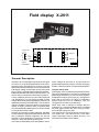
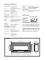
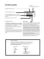
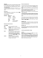
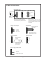
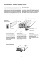
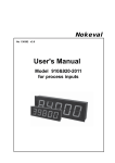
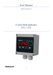
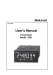
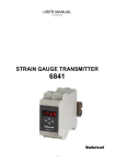
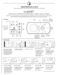
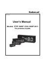
Nokeval
No 110507
User's Manual
Models 575F-1000F-1100-1800F-2011
for process inputs
1
Contents
General Description ....................................................................................... 3
Field display X-2011 ....................................................................................... 3
Indicator family 2000 .................................................................................
Technical specification ..............................................................................
Dimensions ..............................................................................................
How to order .............................................................................................
3
4
4
4
Control panel ................................................................................................... 5
Configuration stage ...................................................................................
Resetting access code .............................................................................
Alarm level setting ....................................................................................
Alarm setting ............................................................................................
5
5
5
5
Configuration .................................................................................................. 6
Configuration parameters ..........................................................................
Alarms ......................................................................................................
Dec - number of decimals .........................................................................
Lo Hi - display scaling ..............................................................................
Lowpass filter ...........................................................................................
Steppass filter ...........................................................................................
Dead - dead zone around zero ..................................................................
Intens - display brigtness ..........................................................................
Input selection ..........................................................................................
External contact function ..........................................................................
Access code functions .............................................................................
Teaching potentiometer position ...............................................................
7
7
7
7
7
7
8
8
8
8
8
8
Connections .................................................................................................... 9
Voltage / current-input ..............................................................................
2-wire transmitter ......................................................................................
Input/output cards .....................................................................................
Potentiometer ...........................................................................................
External contact .......................................................................................
9
9
9
9
9
Field display construction .............................................................................. 10
2000 series input and option cards: ......................................................... 11
Modular indicator serie 2000 .................................................................... 11
Manufacturer:
Nokeval Oy
Yrittäjäkatu 12
37100 NOKIA, FINLAND
Tel. +358 (0)3 342 4800
Fax. +358 (0)3 342 2066
http//:www.nokeval.com
2
Field display X-2011
Display hold
V
Com
mA
24 VDC
2-wire
transmitter
Input
Output
6
5
4
3
2
1
Slot A
Relays
6
5
4
3
2
1
6
5
4
3
2
1
Slot B
Slot C
Relay A1
Relay A2
7 8 9
Power supply
General Description
Indicator X-2011 is designed for general process inputs
0/4..20 mA, 0..5/10V and potentiometers 100Ω-10 kΩ.
Designers main goal has been to achieve a unit with
fast introduction time and easy of use. Input selection
and display scaling can be easily done by front panel
keys (4 keys). Optional alarm level and hysteresis additional card 2000-REL wtih two NC/NO relays - can
also be easily controlled from indicators front panel.
X-2011 measuring accuracy is 0,05% FS (15 bits) and
it is designed for 3-4 digit panel mounted process
display. When wider span is used display value can be
stabilized with freely selectable filter. This operation
makes it possible to use this indicator even as 5 digit
display. If larger numerical value is required same
time with fast display updating time it is recommended
to use indicator model X-2021.
Decimal point position is freely selectable. Separate
access codes for configuration and alarm level control
can be selected. Display brightness can also be
selected via front panel keys. Front panel protection
is IP65 i.e. dust and sprinkling water proof.
There are two alternative power possibilities, one for
mains voltage 85..230 VAC or 24 VDC. Both are
galvanically isolated from inputt. Indicator can supply
24 VDC / 150 mA to sensor or to other field equipment.
Indicator family 2000
Field display X-2011 is a part of a larger product family.
This series field displays are easy to modificate for
different type of inputs e.g. X-2011 can be changed for
Pt100/thermocouple input simply by changing the
input card to type 2021. This kind of modification
doesn't require any kind of calibration, user only
configures the unit with front panel keys.
When input card is changed it changes also the
model type. e.g. if process indicator 2011 is modified
for strain gage indicator with 2041-STG input card,
the model will change to X-2041.
This model X-2011 is basic indicator in this series. If
You require min / max value memory, more alarm
relays, temperature input or better accuracy, You
should use the model X-2021 display..
3
Technical specification
Process inputs:
Range:
Display hold:
Input resistance:
Accuracy:
Sensor supply:
2.5 mm2 removable
57 mm (575F), 100 mm (1000F and
1100F) or 180 mm (1800F)
Power supply
85..240 VAC or 24VDC
Case protection IP65
Weight
575F: 3 kg, 1000F: 5 kg, 1100F: 8 kg,
1800F: 15 kg
Terminals:
Digit size
0..20 mA, 4..20 mA,
0..5 V and 0..10V
-9999..99999
f.ex. 4-20 mA= 58.500..59.500
(span 10.00)
by closing contact
current 50 Ω,
voltage input >1 MΩ
0.05% FS
24 VDC, max. 50 mA
How to order
Potentiometer: 100Ω -10 kΩ
Reference voltage: 2.5 V max load current 25 mA
Accuracy:
0.05 % FS
Alarms:
(option)
XX-2011-REL2-24VDC
XX,=575F,1000F,
1100F or 1800F
Input card
Alarm card REL2
Supply voltage
85..240 VAC or 24VDC
Last parameter always power 24 VDC or 230 VAC
2 alarms, relays max 240 VAC,
2 A, selectable hysteresis 100%,
automatic or manual reset,
selectable direction
General:
Input filter:
Digital, freely selectable
AD-converter:
15 bits (1/32000)
Measuring speed: 7 meas. /second
Temperature effect: 0.005 %/°C
Alarm indicators: 2, A1 and A2
Power supply:
Consumption:
Case material:
Order types doesn't contain optional card symbol
'2000'. e.g. 2000-REL2 is specified only REL2. Unit
may have one input card and two optional cards.
Unit can be updated to other input types only by
changing the input card and adding needed option
cards. Optional cards are same for all 2000-series
units.
Alarm card 2000-REL2 (REL2 with type code)
85..240 VAC or
12..30 VDC / 22..28 VAC
12 W without sensor supply.
F.ex. 24 VDC, 0.5 A
575F: Dark noryl
1000F-1100F-1800F:
black metal
Dimensions:
281, 500, 670 1045
96,120,
130, 210
118,147,
210, 330
13,188,250, 375
281, 455, 625, 1025
301, 482, 650, 1030
Glands:
2 x PG 11
Dimensions shown in the order:
575F, 1000F, 1100F, 1800F
1000F-1800F metal enclosure
575F plastic enclosure
4
Control panel
Conf-LED
Unit is in configuration mode
External contact indicator A3.
Alarm relay indicators A1..A2.
5620.0
Arrow-buttons(▲▼) are used to change
numerical values and when moving in menustructure.
*
Star-key (★) exits selected function.
Configuration stage
Alarm setting
Configuration can be started by pressing and holding
★- and ▲-keys simultaneously for 2 seconds.
Configuration stage is for selecting input, display
scaling and alarm function (NC/NO).
Specified instructions on pages 6-7 Configuration.
If alarm state is secured with access code (ALCode) it
must be entered before user can change/ view alarm
levels (see access code setting on page 7).
Alarm values can be changed and viewed in
measuring stage. Other functions must be done in
configuration mode. Unit has two alarm levels which
can be viewed with ➤-button. After ➤-press lights A1LED and display shows alarm1 level, A1-LED blinks to
inform that unit is in alarm level stage. Second ➤-bush
lights A2-LED and indicator shows alarm 2 level. Third
press returns display into measuring stage. If buttons
are not pressed with in 60 seconds unit returns
automatically into measuring stage.
When A1 or A2 led blinks user can enter edit mode by
pressing ▲ or ▼-key. Values can be changed as
described below. Accept change by -key.
Resetting access code
If configuration access code is forgotten, the access
code can be reset by switching power off and holding
down buttons ★ and ➤ while connecting power back
again.
Alarm level setting
Alarm levels are selected with ▲▼-buttons one number at a time.
Changing begins from the most signifigant digit on the left, decimal point
is selected first. Next digit to right is selected with ➤-button.
Accept and exit with ★ -button.
Value selection
Selecting next digit
400.00
400.00
Desimal point selection
with
-keys before
number selection
Numbers
0...9
5
Configuration
Configuration can be started by pressing and holding
★- and ▲-keys simultaneously for 2 seconds. Arrow
keys ▲▼ moves up and down in main menu. Desired
function is selected with ➤-key. Save mode can be
selected directly by pushing ★-key in main menu.
To save and exit, push ➤ while save is displayed.
Alarm values can be selected in configuration mode or
in measuring mode. Hysteresis and alarm type can be
selected only in configuration mode.
Changes can be restored by selecting text UnDO into
display and pressing ➤-key. Note! Detailed
configuration stage description on next page.
Beginning
★- and ▲
Moving on menu
(▲▼ ) - keys.
rESEt
Auto / manual reset
User = manual reset by front panel key
Auto = automatic reset
Select alarm type, low or high
alarm: LoNo, LoNc, HiNo or HiNc
UnDo
Cancel
and Quit
Type
LoNo/LoNc
SAVE
Save and
Exit
HYST
Select hysteresis
ALn1
Level
ALn2
Alarm level 2 like alarm 1
DEC
Decimal selection -4..0..4
Lo
Value
+
Hi
Set alarm value.
Setting:
Select number amount with decimal
point (▲▼) (f.ex. 125.000) and then
(➤) value (▲▼).
Accept by (★)-key (twice).
+
Set
New value
Set min value of display when input
signal is on mimum value (f.ex. 4 mA)
+
Return
Set maximum value of display when
input signal is on maximum level.
Lopass
Lowpass filter
Stpass
Steppass filter
dEAd
Dead zone around zero
Intens
Brightness of display (1-5).
Default value 3
InPUt
Select input type
Text
4_20 mA
0_20 mA
0_5u
0_10u
SPec
Pot
6
=
=
=
=
=
=
Inputs
4-20 mA
0-20 mA
0-5V
0-10V
Special range
Potentiometer
External contact selection
CONTAC
Display holding, alarm reset
and tare function
OFF
HoLd
CFCODE
Access code for configuration
More information on next page.
ALrESE
ALCODE
CAL
ZEro
NoFiLt
Access code for alarms
CODE
External contact not in use
Display holding, by closing
contact
Alarms reset, by external
contact
Tare function
Bypassing the filter
Calibration. See details on potentiometer calibration.
Configuration parameters
Lopass (➤)
First order digital lowpass filter for input. Functions like
a RC circuit damping variations in the reading. Set the
time constant in seconds (63 % of step change)
0.000 = no damping
0.500 = normal damping
8191 = maximum damping
To enter into configuration mode press and hold ▲ and
★-keys simultaneously for 2 seconds. Save mode can
be selected directly by pushing ★-key in main menu,
otherwise ★-key moves backwards. Words printed in
italic represent indicators display symbols.
Undo, Save (➤)
Exit configuration mode without saving changes
(Undo) or save changes (Save).
Lowpass filter
Alarms
Alm 1 and Alm 2 (➤)
Level
= alarm level
Hyst
= hysteresis, High level alarm
Type
= Alarm type selection
Select one of the following
LoNo, Low level, contact normal open
HiNo, High level, contact normal open
LoNc, Low level, contact normal closed
HiNc, High level, contact normal closed
Reset
Auto or manual reset
User = manual reset from front panel or
external contact (conf menu - contac)
Auto = automatic reset
100%
63%
0%
Lopass
Stpass (➤)
Steppass filter. When strong damping (see Lopass
filter) in used, it takes very long for the indicator to settle
after large changes in input value. This can be eliminated with steppass filter. Normally the unfiltered input
value (dashed line in the graph) fluctuates around the
filtered value. However after large changes the sign of
the difference between unfiltered and filtered value will
remain unchanged for a while. When this time exceeds
the Stpass value (in seconds) the lopass filter is reset
and the indicator will jump to the current input value.
Dec (➤)
Number of decimals in display. Select 0…4 with ▲▼keys and accept with ★-key. When Dec value is
negative the corresponding number of last digits is
rounded to zero. f.ex. Dec = -2: two last digits are
always zero.
Lo, Hi (➤)
Display scaling. Lo-value represents display scaling
at 4 mA (or 0 mA / 0V) and Hi-value which is represents
display scaling at 20 mA (10V), F. ex. 4 mA=0.0 and
20 mA=100.0.
When value is in display it can be changed by
pushing ➤-key or continue straight into SAVE mode
with ★.
Steppass filter
++
+ -+ - +
- +
Lopas s
- - -- - - Ste ppas s
7
+ -+
Dead (➤)
Dead zone around zero. If the input reading is smaller
than the Dead value, the display is rounded to zero.
This is especially handy in weighing and flow measurement applications.
To prevent negative values only, set Dead = 0. To
disable the dead zone, set Dead = -1 or any negative
value.
Access code functions
Access code can be entered when the display shows
-Code-. Access code is formed with ▲▼★➤-keys.
Each time key is pressed line (-) moves from left to
right.
Entering access code must be started within 3 second
after text -Code- appears to display.
Total number of combinations is 46 = 4096.
Note! If You enter ★★★★★★, it means that access
code is not used.
If configuration access code is forgotten, the access
code can be reset by switching power off and holding
down buttons ★ and ➤ while connecting power back
again.
Intens (➤)
Display brightness 1-5 (st to select, accept with ★ ),
factory default 4, (5=brightest).
Input selection
Input (➤)
Select input
Display
4_20 mA
0_20 mA
0_5u
0_10u
SPEC
Pot
Input
= 4-20 mA
= 0-20 mA
= 0-5V
= 0-10V
= Factory settings
= Potentiometer
To remember access code better it is recommended to
give 'names' to buttons: 1=▲, 2=▼, 3=★, 4=➤. This
helps You to form codes with numbers e.g. number
143311 = ▲➤★★▲▲.
CFCode (➤)
Access code for configuration mode. If You feel that
You entered wrong code, You can enter it again. See
detailed instructions above.
External contact function
➤)
Contac (➤
OFF
= External contact not ni use
Hold
= Display holding, by external closing
contact
ALrESE
= Alarms reset, by external contact (if
user function selected from the
reset function)
ZEro
= Tare function by external contact or
front panel ★-key. Tare function
resets of that moment display value.
(Tare can be removed by pressing
the front panel ★ and ➤ -keys at the
same time)
NoFILt
= Lopass filter bypass. Use when
there is a switch indicating large
changes in input value.
ALCode (➤)
Access code for alarm level mode. Must be entered
to access into alarm level setting mode from normal
measuring mode.
Teaching potentiometer range
CAL (➤)
Select text CAL into display with ▲▼-keys. Push ➤.
Enter access code ★★★★★★.
Select with ▲▼ -keys text POt into display and led
A1 lits.Turn potentiometer into minimum and press ➤key for 1 second. Select ▲▼ text Pot and led A2. Turn
potentiometer into maximum position and press ➤.
Exit to main menu with ★-key.
8
X-2011 Connections
Input/output cards
Display Hold (6)
V
Com
mA
24 VDC
2-wire
transmitter
Input
6
5
4
3
2
1
Slot A
Output
6
5
4
3
2
1
Alarms
Nc
No
Nc
No
Slot B
6
5
4
3
2
1
7 8 9
Power supply
85..240 VAC
(connectors 7 and 8 grey connector)
or 24 VDC (green connettor 7 and 9
no polarity)
6
5
4
3
2
1
+ 0..5/10V
- Common
+ 0/4..20 mA
Potentiometer size:
100Ω-10kΩ
+
Open jumper J2 when
potentiometer is used
External contact
2-wire transmitter
4..20 mA
+
Power supply for
transmitter 24 V
max. 150 mA
6
5
4
3
2
1
(Slot A)
Sensor supply 24 VDC /50 mA
6
5
4
3
2
1
Relay A2
Potentiometer
2-wire transmitter
6
5
4
3
- 2
+ 1
Relay A1
Slot C
Slot A is for sensor input and
slots B and C for optional cards.
Voltage / current-input
6
5
4
3
2
1
- Common
+ 24 VDC, max. 50 mA
9
Construction of field display series
The field display series is modular and easy to assemble according to customers wishes. The basic
construction consists of mother board with tree slots,
A, B and C. Slot A determines meter type and provides
always input signal. Slot B and C are interchangeable.
As factory delivery input signal is always installed into
slot A, output into slot B and alarms into slot C. In case
of f.ex 4 alarms and relay card with 2 change-over
contact (2 + 2 relays) are used, you must place second
relay card into slot B.
You can have different types of meters by only
changing the input card in slot A. Data sheet of each
type of meter dictates the possible combinations.
Recalibration of card is not needed; only scaling and
other settings must be set using front panel keys.
All cards have
calibration memory
Slots A-C
A
B
C
Power supply 12...32 VDC
(Green connector)
or 85...240 VAC
(Grey connector)
Change of meter type:
Input card is placed always to
slot A. By changing input card
you can get an other type of
meter. You can change meter
with pulse input to meter with
current input, thermocouple,
strain gage etc.
Additional slots:
Additional cards provide output
4..20 mA, alarms, serial interface, BCD output etc. Meter
data sheet dictates possible
combinations. grey connectors
allow line voltage 110..240 VAC
(relay contacts).
Control electronic case:
10
Power supply:
There are two different mother
boards power supply 85..240
VAC and 12..32 VDC. VDCmother board accepts
24 VAC. Connectors are colour
coded.
Modular field display series 575F...1800F
Display
Option cards
Alarm cards:
2 relay card, 4 alarm types,
change over contacts
3 relay card, closing contacts
4 I/O-ports
E²
6543.21
E²
DAC
Sensor supply:
24VDC,
150 mA
2021
E²
2011
E²
ADC
Process inputs (model 2011):
0..20 mA, 4..20 mA
0..5/10 V
Potentiometer 100Ω..5kΩ
uP
Input card contains:
- microprocessor
- bus control
- keys control
- display control
Model 2011:
2 relays change over contacts
(also with remote reset)
Output cards (not for 2011):
0/4..20 mA, 0..10 V
RS232 or RS485
Power supply:
85..240VAC or
12..32 VDC / 24 VAC
Model 2021 contains also process inputs but it can also measure RTD-sensors and thermocouples. 2021 has very accurate and fast A/D-converter (16 bit 1/64 000).
2000 series input and option cards:
2011-IN
2021-MU
2031-IR
2041-SG
2051-PU
2061-CO
2066-SEC
2071-RS
2081-BCD
2000-BASE
2000-REL2
2000-REL3
2000-OUT
2000-RS
2000-I/O
Process input
Multi input
Infrared sensor input
Strain gage measurement
Scaleable frequency indicator
Counter input (max 5 kHz)
Timer function, s/min/h ext.
Serial input RS232 / RS485
BCD-, Gray- binary code input
(1-5 digits)
11
Base card with power supply
Alarm card, NO/NC
Alarm card, Closing contacts
Output card, U and I
Serial output RS232 or RS485
4 pcs input /output ports
(60 V / 100 mA)
Manufacturer:
Nokeval Oy
Yrittäjäkatu 12
37100 NOKIA
Tel. +358 (0)3 342 4800
Fax. +358 (0)3 342 2066
http://www.nokeval.com
12