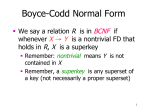
1
Logic Engine User Manual 56
To direct the actions of the 2910, the
designer will usually need to make available
DESIGNER’s ARCHITECTURE
several status signals from the architecture.
0
LD.L
The 2910 sequencer accepts a single signal
TST.L 1
2
as a test input. 2910 instructions may inter3
rogate this signal and branch based on its
4
..
value. The designer of a microprogrammed
.
system faces the problem of extracting the
desired signal from the architecture and presenting it to the sequencer at the proper
4
time. Of the several mechanisms for selecting one signal from many, perhaps the easi2910
COMMANDS
INSTRUCTION
est and simplest is to construct a multiplexer
0
3
in the architecture. Since in each microin20
struction we know which signal, if any, is
required for testing, we may use some of the
2910
command bits in the microinstruction to
microsequencer
DESIGNER’s TEST INPUT
serve as the select code for the multiplexer.
The full design from which this example is
taken requires about a dozen test inputs, so a
16-input multiplexer with a four-bit select code is appropriate. Fig. 2 shows the structure of the
test input selection apparatus, centered around the test multiplexer INMUX. You will notice that
we have decided to allocate the first four microinstruction command bits (bits 0-3) to control the
test multiplexer. This is an arbitrary choice.
Copyright ©2001 Indiana University Computer Science Department