1
TM
General Purpose
AC Motors
Manual Number: IH-USER-M-WO
THIS PAGE
INTENTIONALLY
LEFT BLANK
WARNING Thank you for purchasing automation equipment from Automationdirect.com™, doing business as
AutomationDirect. We want your new automation equipment to operate safely. Anyone who installs
or uses this equipment should read this publication (and any other relevant publications) before
installing or operating the equipment.
To minimize the risk of potential safety problems, you should follow all applicable local and national
codes that regulate the installation and operation of your equipment. These codes vary from area to
area and usually change with time. It is your responsibility to determine which codes should be
followed, and to verify that the equipment, installation, and operation is in compliance with the
latest revision of these codes.
At a minimum, you should follow all applicable sections of the National Fire Code, National
Electrical Code, and the codes of the National Electrical Manufacturer's Association (NEMA). There
may be local regulatory or government offices that can also help determine which codes and
standards are necessary for safe installation and operation.
Equipment damage or serious injury to personnel can result from the failure to follow all applicable
codes and standards. We do not guarantee the products described in this publication are suitable for
your particular application, nor do we assume any responsibility for your product design,
installation, or operation.
Our products are not fault-tolerant and are not designed, manufactured or intended for use or resale
as on-line control equipment in hazardous environments requiring fail-safe performance, such as in
the operation of nuclear facilities, aircraft navigation or communication systems, air traffic control,
direct life support machines, or weapons systems, in which the failure of the product could lead
directly to death, personal injury, or severe physical or environmental damage ("High Risk
Activities"). AutomationDirect specifically disclaims any expressed or implied warranty of fitness for
High Risk Activities.
For additional warranty and safety information, see the Terms and Conditions section of our catalog.
If you have any questions concerning the installation or operation of this equipment, or if you need
additional information, please call us at 770-844-4200.
This publication is based on information that was available at the time it was printed. At
AutomationDirect we constantly strive to improve our products and services, so we reserve the right
to make changes to the products and/or publications at any time without notice and without any
obligation. This publication may also discuss features that may not be available in certain revisions of
the product.
Trademarks
This publication may contain references to products produced and/or offered by other companies.
The product and company names may be trademarked and are the sole property of their respective
owners. AutomationDirect disclaims any proprietary interest in the marks and names of others.
Copyright 2007, 2008, 2009 Automationdirect.com™ Incorporated
All Rights Reserved
No part of this manual shall be copied, reproduced, or transmitted in any way without the prior,
written consent of Automationdirect.com™ Incorporated. AutomationDirect retains the exclusive
rights to all information included in this document.
AVERTISSEMENT Nous vous remercions d'avoir acheté l'équipement d'automatisation de Automationdirect.com™, en
faisant des affaires comme AutomationDirect. Nous tenons à ce que votre nouvel équipement
d'automatisation fonctionne en toute sécurité. Toute personne qui installe ou utilise cet équipement
doit lire la présente publication (et toutes les autres publications pertinentes) avant de l'installer ou
de l'utiliser.
Afin de réduire au minimum le risque d'éventuels problèmes de sécurité, vous devez respecter tous
les codes locaux et nationaux applicables régissant l'installation et le fonctionnement de votre
équipement. Ces codes diffèrent d'une région à l'autre et, habituellement, évoluent au fil du temps. Il
vous incombe de déterminer les codes à respecter et de vous assurer que l'équipement, l'installation
et le fonctionnement sont conformes aux exigences de la version la plus récente de ces codes.
Vous devez, à tout le moins, respecter toutes les sections applicables du Code national de
prévention des incendies, du Code national de l'électricité et des codes de la National Electrical
Manufacturer's Association (NEMA). Des organismes de réglementation ou des services
gouvernementaux locaux peuvent également vous aider à déterminer les codes ainsi que les normes
à respecter pour assurer une installation et un fonctionnement sûrs.
L'omission de respecter la totalité des codes et des normes applicables peut entraîner des dommages
à l'équipement ou causer de graves blessures au personnel. Nous ne garantissons pas que les produits
décrits dans cette publication conviennent à votre application particulière et nous n'assumons aucune
responsabilité à l'égard de la conception, de l'installation ou du fonctionnement de votre produit.
Nos produits ne sont pas insensibles aux défaillances et ne sont ni conçus ni fabriqués pour
l'utilisation ou la revente en tant qu'équipement de commande en ligne dans des environnements
dangereux nécessitant une sécurité absolue, par exemple, l'exploitation d'installations nucléaires, les
systèmes de navigation aérienne ou de communication, le contrôle de la circulation aérienne, les
équipements de survie ou les systèmes d'armes, pour lesquels la défaillance du produit peut
provoquer la mort, des blessures corporelles ou de graves dommages matériels ou
environnementaux («activités à risque élevé»). La société AutomationDirect nie toute garantie
expresse ou implicite d'aptitude à l'emploi en ce qui a trait aux activités à risque élevé.
Pour des renseignements additionnels touchant la garantie et la sécurité, veuillez consulter la section
Modalités et conditions de notre documentation. Si vous avez des questions au sujet de l'installation
ou du fonctionnement de cet équipement, ou encore si vous avez besoin de renseignements
supplémentaires, n'hésitez pas à nous téléphoner au 770-844-4200.
Cette publication s'appuie sur l'information qui était disponible au moment de l'impression. À la
société AutomationDirect, nous nous efforçons constamment d'améliorer nos produits et services.
C'est pourquoi nous nous réservons le droit d'apporter des modifications aux produits ou aux
publications en tout temps, sans préavis ni quelque obligation que ce soit. La présente publication
peut aussi porter sur des caractéristiques susceptibles de ne pas être offertes dans certaines versions
révisées du produit.
Marques de commerce
La présente publication peut contenir des références à des produits fabriqués ou offerts par d'autres
entreprises. Les désignations des produits et des entreprises peuvent être des marques de commerce
et appartiennent exclusivement à leurs propriétaires respectifs. AutomationDirect nie tout intérêt
dans les autres marques et désignations.
Copyright 2007, 2008, 2009 Automationdirect.com™ Incorporated
Tous droits réservés
Nulle partie de ce manuel ne doit être copiée, reproduite ou transmise de quelque façon que ce soit
sans le consentement préalable écrit de la société Automationdirect.com™ Incorporated.
AutomationDirect conserve les droits exclusifs à l'égard de tous les renseignements contenus dans le
présent document.
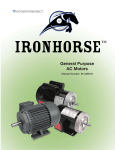
IRONHORSE GENERAL
PURPOSE AC MOTORS
USER MANUAL
Please include the Manual Number and the Manual Issue, both shown below, when
communicating with Technical Support regarding this publication.
Manual Number:
IH-USER-M-WO
Issue:
Third Edition
Issue Date:
06/2009
Publication History
Issue
Date
Description of Changes
First Edition
09/2007
Original Issue
1st Ed., Rev. A
11/2007
Chapter 2 wiring diagrams
Second Edition
12/2008
User manual name change (previously “IH-USER-M”)
Deleted obsolete motor MTR-002-1AB18
Added MTC-xxx-xxxxxCK cast iron TC-frame motors
Revised specs for existing MTC-xxx-xxxxx cast iron T-frame motors
Third Edition
06/2009
Added 1200 and 3600 rpm motors
THIS PAGE
INTENTIONALLY
LEFT BLANK
TABLE OF CONTENTS
Chapter 1: Getting Started . . . . . . . . . . . . . . . . . . . . . . .1–1
Manual Overview . . . . . . . . . . . . . . . . . . . . . . . . . . . . . . . . . .1–2
Overview of this Publication . . . . . . . . . . . . . . . . . . . . . . . . . . . . .1–2
Who Should Read This Manual . . . . . . . . . . . . . . . . . . . . . . . . . . .1–2
Technical Support . . . . . . . . . . . . . . . . . . . . . . . . . . . . . . . . . . . . .1–2
Special Symbols . . . . . . . . . . . . . . . . . . . . . . . . . . . . . . . . . . . . . .1–2
Available Models . . . . . . . . . . . . . . . . . . . . . . . . . . . . . . . . . . .1–3
Single-Phase Motors Features and Specifications . . . . . . . . . . . . . .1–3
Three-Phase Motors Features and Specifications . . . . . . . . . . . . . .1–4
Receiving and Inspection . . . . . . . . . . . . . . . . . . . . . . . . . . .1–15
Unpacking . . . . . . . . . . . . . . . . . . . . . . . . . . . . . . . . . . . . . . . . . .1–15
IronHorse Part Number Information . . . . . . . . . . . . . . . . . . . . . .1–15
Reshipping . . . . . . . . . . . . . . . . . . . . . . . . . . . . . . . . . . . . . .1–16
Long Term Storage . . . . . . . . . . . . . . . . . . . . . . . . . . . . . . . .1–16
Warranty . . . . . . . . . . . . . . . . . . . . . . . . . . . . . . . . . . . . . . . .1–16
3rd Edition
06/2009
IronHorse™ General Purpose Motors User Manual
TC–i
Table of Contents
Chapter 2: Mounting & Initial Startup . . . . . . . . . . . . . . .2–1
Safety Information . . . . . . . . . . . . . . . . . . . . . . . . . . . . . . . . . .2–2
Motor Dimensions . . . . . . . . . . . . . . . . . . . . . . . . . . . . . . . . .2–3
56C-Frame Single-phase Motor Dimensions . . . . . . . . . . . . . . . . .2–3
56C-Frame Three-phase Motor Dimensions . . . . . . . . . . . . . . . . .2–3
T-Frame Three-phase Motor Dimensions . . . . . . . . . . . . . . . . . . . .2–4
TC-Frame Three-phase Motor & C-Flange Dimensions . . . . . . . . .2–8
Terminal Diagrams . . . . . . . . . . . . . . . . . . . . . . . . . . . . . . . . .2–9
Motor Mounting . . . . . . . . . . . . . . . . . . . . . . . . . . . . . . . . . .2–10
STABLE™ Slide Bases . . . . . . . . . . . . . . . . . . . . . . . . . . . . . . . . . .2–10
Proper Installation Conditions . . . . . . . . . . . . . . . . . . . . . . . . . . .2–11
Coupling Alignment . . . . . . . . . . . . . . . . . . . . . . . . . . . . . . . . . .2–11
Motor Nameplate & Starter Information . . . . . . . . . . . . . . . .2–12
Typical IronHorse Motor Nameplate . . . . . . . . . . . . . . . . . . . . . .2–12
Motor Starter Information . . . . . . . . . . . . . . . . . . . . . . . . . . . . . .2–12
Locked Rotor Amps . . . . . . . . . . . . . . . . . . . . . . . . . . . . . . . . . . .2–13
Inspection Before Startup . . . . . . . . . . . . . . . . . . . . . . . . . . .2–14
Initial Startup Inspection . . . . . . . . . . . . . . . . . . . . . . . . . . . .2–14
Chapter 3: Preventative Ongoing Maintenance . . . . . . . .3–1
Routine Maintenance . . . . . . . . . . . . . . . . . . . . . . . . . . . . . . .3–2
Bearing Size Information . . . . . . . . . . . . . . . . . . . . . . . . . . . . .3–3
Chapter 4: Accessories . . . . . . . . . . . . . . . . . . . . . . . . . . .4–1
Capacitors and Centrifugal Switches . . . . . . . . . . . . . . . . . . . .4–2
C-Flange Kits . . . . . . . . . . . . . . . . . . . . . . . . . . . . . . . . . . . . . .4–3
STABLE Slide Bases . . . . . . . . . . . . . . . . . . . . . . . . . . . . . . . . .4–4
TC–ii
IronHorse™ General Purpose Motors User Manual
3rd Edition
06/2009
Table of Contents
Chapter 5: Reference . . . . . . . . . . . . . . . . . . . . . . . . . . . .5–1
Using IronHorse Motors with AC Drives . . . . . . . . . . . . . . . . .5–2
Voltage Spike Considerations for AC Drive Control . . . . . . . . . . . .5–2
Double Punched Motors . . . . . . . . . . . . . . . . . . . . . . . . . . . . .5–3
F1 and F2 Mounting . . . . . . . . . . . . . . . . . . . . . . . . . . . . . . . .5–4
Junction Box Dimensions . . . . . . . . . . . . . . . . . . . . . . . . . . . .5–5
Minimum Sheave Diameters . . . . . . . . . . . . . . . . . . . . . . . . . .5–6
Decibel Levels . . . . . . . . . . . . . . . . . . . . . . . . . . . . . . . . . . . . .5–7
Shipping Crate Dimensions . . . . . . . . . . . . . . . . . . . . . . . . . . .5–8
3rd Edition
06/2009
IronHorse™ General Purpose Motors User Manual
TC–iii
THIS PAGE
INTENTIONALLY
LEFT BLANK
GETTING STARTED
CHAPTER
1
In This Chapter...
Manual Overview . . . . . . . . . . . . . . . . . . . . . . . . . . . . . . .1–2
Overview of this Publication . . . . . . . . . . . . . . . . . . . . . . . . . .1–2
Who Should Read This Manual . . . . . . . . . . . . . . . . . . . . . . . .1–2
Technical Support . . . . . . . . . . . . . . . . . . . . . . . . . . . . . . . . . .1–2
Special Symbols . . . . . . . . . . . . . . . . . . . . . . . . . . . . . . . . . . .1–2
Available Models . . . . . . . . . . . . . . . . . . . . . . . . . . . . . . . .1–3
Single-Phase Motors Features and Specifications . . . . . . . . . . .1–3
Three-Phase Motors Features and Specifications . . . . . . . . . . .1–4
Receiving and Inspection . . . . . . . . . . . . . . . . . . . . . . . .1–15
Unpacking . . . . . . . . . . . . . . . . . . . . . . . . . . . . . . . . . . . . . .1–15
IronHorse Part Number Information . . . . . . . . . . . . . . . . . . .1–15
Reshipping . . . . . . . . . . . . . . . . . . . . . . . . . . . . . . . . . . .1–16
Long Term Storage . . . . . . . . . . . . . . . . . . . . . . . . . . . . .1–16
Warranty . . . . . . . . . . . . . . . . . . . . . . . . . . . . . . . . . . . . .1–16
Chapter 1: Getting Started
Manual Overview
Overview of this Publication
The IronHorse General Purpose AC Motor User Manual describes the installation,
maintenance and use of all IronHorse General Purpose Motors.
Who Should Read This Manual
This manual contains important information for those who will install, maintain,
use and/or resell any of the IronHorse motors.
Technical Support
By Telephone: 770-844-4200
(Mon.-Fri., 9:00 a.m.-6:00 p.m. E.T.)
On the Web: support.automationdirect.com
Our technical support group is glad to work with you in answering your questions.
If you cannot find the solution to your particular application, or, if for any reason
you need additional technical assistance, please call technical support at
770-844-4200. We are available weekdays from 9:00 a.m. to 6:00 p.m. Eastern
Time.
We also encourage you to visit our web site where you can find technical and
non-technical information about our products and our company. Visit us at
www.automationdirect.com.
Special Symbols
When you see the “notepad” icon in the left-hand margin, the paragraph to its
immediate right will be a special note.
When you see the “exclamation mark” icon in the left-hand margin, the paragraph to
its immediate right will be a WARNING. This information could prevent injury, loss
of property, or even death (in extreme cases).
1–2
IronHorse General Purpose Motors User Manual
3rd Edition
06/2009
Chapter 1: Getting Started
Available Models
Single-Phase Motors Features and Specifications
Rolled Steel 56C Frame Single-Phase Motors
IronHorse single-phase 56C frame motors are
available from 1/3 hp to 1-1/2 hp. All models
have a TEFC rolled steel frame, cast aluminum
end bell and removable mounting bases. All
motors are NEMA B design.
1800 rpm Motor Specifications & Performance Data
Motor Specifications – Single-Phase 56C Frame Motors – 1800 rpm
Part
Number
Base
RPM
HP
MTR-P33-1AB18
MTR-P50-1AB18
MTR-P75-1AB18
MTR-001-1AB18
MTR-1P5-1AB18
Voltage
NEMA Service
Frame Factor
1/3
1/2
3/4
1800 115/208-230
1
56C
flange
mount
1.15
1-1/2
F.L. Amps
@
115V/230V
Approx
Weight
(lb)
6.6 / 3.3
26
8.8 / 4.4
28
11.0 / 5.5
32
13.6 / 6.8
38
15.2 / 7.6
45
Note: Please review the AutomationDirect Terms & Conditions for warranty and service on
this product.
MTR-P33-1AB18
MTR-P50-1AB18
MTR-P75-1AB18
MTR-001-1AB18
MTR-1P5-1AB18
3rd Edition
06/2009
HP
Current @ 115V/230V
Torque (lb·ft)
F.L.
(Amps)
F.L. Rotor
Efficiency
Power Inertia
230V
Break
Full Locked Full Locked
Factor (lb·ft2)
(%)
No
Load Rotor Load Rotor
Load
down
1/3
2.2
6.6 / 3.3
31 / 18
1.02
3.06
2.81
56.0
0.62
0.075
1/2
2.93
8.8 / 4.4
37 / 21
1.52
4.56
4.18
57.0
0.63
0.080
3.67
11.0 / 5.5 55 / 32
2.29
6.30
5.73
65.0
0.65
0.095
1
4.53
13.6 / 6.8 75 / 43
3.04
8.36
7.60
68.0
0.66
0.120
1-1/2
5.07
15.2 / 7.6 120 / 65 4.57
11.43
10.28
71.0
0.75
0.142
3/4
1725
Part
Number
F.L. RPM
Performance Data – Single-Phase 56C Frame Motors – 1800 rpm
(230V data except as indicated)
IronHorse General Purpose Motors User Manual
1–3
Chapter 1: Getting Started
Three-Phase Motors Features and Specifications
Rolled Steel 56C Frame Three-Phase Motors
IronHorse 56C rolled steel frame three-phase
motors are available from 1/3 hp to 2 hp. All
models have a TEFC frame, cast aluminum end
bell and removable mounting bases.
1800 & 3600 rpm Motor Specifications
1800 RPM
MTR-P33-3BD18 1/3
MTR-P50-3BD18 1/2
MTR-P75-3BD18 3/4
1
MTR-001-3BD18
MTR-1P5-3BD18 1-1/2
2
MTR-002-3BD18
3600 RPM
MTR-P33-3BD36 1/3
MTR-P50-3BD36 1/2
MTR-P75-3BD36 3/4
1
MTR-001-3BD36
MTR-1P5-3BD36 1-1/2
2
MTR-002-3BD36
Phase
Voltage Housing
NEMA Service
Frame Factor
TEFC
rolled
steel
frame
1800
HP
3
3600
Part
Number
Base
RPM
Motor Specifications – Three-Phase 56C Frame Motors – 1800 & 3600 rpm
cast
56C
208aluminum flange
230/460
end bell mount
1.15
F1
conduit
box
location
F.L. Amps Approx
@
Weight
230V/460V (lb)
1800 RPM
1.6 / 0.8
23
2.0 / 1.0
24
2.8 / 1.4
26
3.6 / 1.8
29
4.8 / 2.4
33
6.0 / 3.0
42
3600 RPM
1.6 / 0.8
23
2.2 / 1.1
24
2.9 / 1.5
26
3.6 / 1.8
28
4.6 / 2.3
34
6.0 / 3.0
43
Note: Please review the AutomationDirect Terms & Conditions for warranty and service on this
product.
1–4
IronHorse General Purpose Motors User Manual
3rd Edition
06/2009
Chapter 1: Getting Started
Three-Phase Motors Features and Specifications (continued)
Rolled Steel 56C Frame Three-Phase Motors
1800 rpm Motor Performance Data
Part
Number
HP
MTR-P33-3BD18 1/3
MTR-P50-3BD18 1/2
MTR-P75-3BD18 3/4
1
MTR-001-3BD18
MTR-1P5-3BD18 1-1/2
2
MTR-002-3BD18
Part
Number
NEMA
Design
Performance Data – Three-Phase 56C Frame Motors – 1800 rpm
(460V data except as indicated)
B
n/a
n/a
Minimum
Current @ 230V/460V
(Amps)
F.L. Speed (rpm)
RPM
Locked
CT
VT
No Load Full Load
Rotor
1725
Torque (lb·ft)
HP
900
Maximum
Speed (rpm)
Full Locked Break
CHP*
Load Rotor -down
MTR-P33-3BD18 1/3 1.02
MTR-P50-3BD18 1/2 1.52
MTR-P75-3BD18 3/4 2.29
1
3.02
MTR-001-3BD18
MTR-1P5-3BD18 1-1/2 4.57
2
6.09
MTR-002-3BD18
360
Safe
0.53 / 0.27
1.6 / 0.8
8/4
0.67 / 0.33
2.0 / 1.0
12 / 6
0.93 / 0.47
2.8 / 1.4
18 / 9
1.2 / 0.6
3.6 / 1.8
24 / 12
1.53 / 0.77
4.8 / 2.4
36 / 18
2.0 / 1.0
6.0 / 3.0
48 / 24
F.L.
Efficiency
(%)
F.L.
Power
Factor
Rotor
Inertia
(lb·ft2)
2.55
2.81
67.0
0.70
0.058
3.80
4.18
69.0
0.72
0.068
5.73
6.30
71.0
0.74
0.075
7.55
8.31
73.0
0.76
0.086
10.28
11.43
75.0
0.78
0.108
13.70
15.23
77.0
0.80
0.143
2700
5400
* Maximum Constant HP RPM is for direct coupled loads.
3rd Edition
06/2009
IronHorse General Purpose Motors User Manual
1–5
Chapter 1: Getting Started
Three-Phase Motors Features and Specifications (continued)
Rolled Steel 56C Frame Three-Phase Motors
3600 rpm Motor Performance Data
Part
Number
HP
MTR-P33-3BD36 1/3
MTR-P50-3BD36 1/2
MTR-P75-3BD36 3/4
1
MTR-001-3BD36
MTR-1P5-3BD36 1-1/2
2
MTR-002-3BD36
Part
Number
NEMA
Design
Performance Data – Three-Phase 56C Frame Motors – 3600 rpm
(460V data except as indicated)
B
n/a
n/a
Minimum
Current @ 230V/460V
(Amps)
F.L. Speed (rpm)
RPM
Locked
CT
VT
No Load Full Load
Rotor
3450
Torque (lb·ft)
HP
1725
Maximum
Speed (rpm)
Full Locked Break
CHP*
Load Rotor -down
MTR-P33-3BD36 1/3 0.50
MTR-P50-3BD36 1/2 0.75
MTR-P75-3BD36 3/4 1.13
1
1.50
MTR-001-3BD36
MTR-1P5-3BD36 1-1/2 2.25
2
3.00
MTR-002-3BD36
690
Safe
1.2 / 0.59
1.6 / 0.8
9/5
1.4 / 0.7
2.2 / 1.1
14 / 7
1.5 / 0.75
2.9 / 1.5
17 / 8.9
1.7 / 0.85
3.6 / 1.8
25 / 13
1.8 / 0.9
4.6 / 2.3
29 / 17
3.4 / 1.7
6.0 / 3.0
57 / 30
F.L.
Efficiency
(%)
F.L.
Power
Factor
Rotor
Inertia
(lb·ft2)
3.0
3.0
57.0
0.71
0.084
4.4
4.5
62.0
0.71
0.095
6.0
5.8
67.0
0.78
0.107
7.9
7.1
69.0
0.82
0.122
11.2
8.4
72.0
0.85
0.143
21.5
13.9
75.0
0.78
0.188
5400
5400
* Maximum Constant HP RPM is for direct coupled loads.
1–6
IronHorse General Purpose Motors User Manual
3rd Edition
06/2009
Chapter 1: Getting Started
Three-Phase Motors Features and Specifications (continued)
Cast Iron T-Frame
Cast Iron TC-Frame
IronHorse 1800 rpm T-frame cast iron industrial duty motors are available from
1–300 hp, and TC-frame motors are available from 1–100 hp. Optional C-face
kits are available for all IronHorse T-frame motors. All models have a TEFC frame
and full length mounting feet.
1800 rpm Motor Specifications
MTC-1P5-3BD18
MTC-1P5-3BD18CK(1)
MTC-002-3BD18
MTC-002-3BD18CK(1)
MTC-003-3BD18
MTC-003-3BD18CK(1)(3)
MTC-005-3BD18(3)
MTC-005-3BD18CK(1)(3)
MTC-7P5-3BD18(3)
MTC-7P5-3BD18CK(1)(3)
1
1.5
2
3
5
7.5
143TC
145T
145TC
145T
145TC
182T
182TC
184T
184TC
213T
213TC
Service
Factor
Holes/Foot
Shaft
Material
Conduit Box
Location(2)
Housing
Voltage
143T
1045 CS
MTC-001-3BD18CK(1)
TEFC cast iron
MTC-001-3BD18
HP
208-230/460
Part Number
NEMA
Frame
Motor Specifications – T & TC(1) Frame Three-Phase Motors – 1800 rpm
Approx
F.L. Amps
Ship
@
Weight
230V/460V
(lb)
F1(F2) 2
3.0 / 1.5
F1(F2) 3
4.2 / 2.1
F1(F2) 3
5.4 / 2.7
1.15
F1(F2) 2
7.72 / 3.86
F1(F2) 3
11.8 / 5.9
F1(F2) 2
18.6 / 9.3
55
61
55
67
60
69
90
112 (3)
110 (3)
125 (3)
150 (3)
170 (3)
1) TC-frame motors are T-frame motors with applicable C-face accessory kits installed.
2) F1(F2) indicates F1 conduit box mounting location, field convertible to F2.
(Refer to “Chapter 5: Reference” for further information regarding F1 and F2 mounting.)
NOTES 3 & 4: Please review the AutomationDirect Terms & Conditions for warranty and
service on this product.
3) For motors weighing over 100 lbs: A) LTL shipment required. B) Order before 4:00 p.m.
EST for same day shipment. C) You must have a receiving loading dock. D) Not available in
Hawaii or Puerto Rico.
4) For warranty on motors 50 hp and above, motors must be inspected by an EASA motor
repair or service center. See AutomationDirect Terms & Conditions for details.
*** TABLE CONTINUED ON NEXT PAGE ***
3rd Edition
06/2009
IronHorse General Purpose Motors User Manual
1–7
Chapter 1: Getting Started
*** TABLE CONTINUED FROM PREVIOUS PAGE ***
20
25
30
40
50(4)
60(4)
75(4)
100(4)
254T
254TC
256T
256TC
284T
284TC
286T
286TC
324T
324TC
326T
326TC
364T
364TC
365T
365TC
405T
405TC
Holes/Foot
Service
Factor
Voltage
Housing
Shaft
Material
Conduit Box
Location(2)
215TC
1045 CS
15
215T
TEFC cast iron
10
208-230/460
Approx
F.L. Amps
Ship
@
Weight
230V/460V
(lb)
F1(F2) 3
24.8 / 12.4
F1(F2) 2
35.4 / 17.7
F1(F2) 3
47.6 / 23.8
F1
2
56.4 / 28.2
F1
3
67.2 / 33.6
F1
2
93.0 / 46.5
F1
3
F1
2
139.4 / 69.7
F1
3
172.8 / 86.4
F1
3
230 / 115
1.15
114.6 / 57.3
179 (3)
198 (3)
290 (3)
310 (3)
326 (3)
360 (3)
400 (3)
440 (3)
451 (3)
470 (3)
589 (3)
608 (3)
640 (3)
652 (3)
760 (3)
777 (3)
803 (3)
837 (3)
1300 (3)
1335 (3)
125(4)
444T
F1(F2) 2
274 / 137
1433 (3)
150(4)
445T
F1(F2) 3
326 / 163
1575 (3)
F1(F2) 3
446 / 223
1858 (3)
- / 282
2508 (3)
- / 334
2728 (3)
200(4) 445/7T
250(4)
449T
300(4)
449T
4140
CS
MTC-010-3BD18(3)
MTC-010-3BD18CK(1)(3)
MTC-015-3BD18(3)
MTC-015-3BD18CK(1)(3)
MTC-020-3BD18(3)
MTC-020-3BD18CK(1)(3)
MTC-025-3BD18(3)
MTC-025-3BD18CK(1)(3)
MTC-030-3BD18(3)
MTC-030-3BD18CK(1)(3)
MTC-040-3BD18(3)
MTC-040-3BD18CK(1)(3)
MTC-050-3BD18(3)(4)
MTC-050-3BD18CK(1)(3)(4)
MTC-060-3BD18 (3)(4)
MTC-060-3BD18CK(1)(3)(4)
MTC-075-3BD18(3)(4)
MTC-075-3BD18CK(1)(3)(4)
MTC-100-3BD18(3)(4)
MTC-100-3BD18CK(1)(3)(4)
MTC-125-3BD18(3)(4)
MTC-150-3BD18(3)(4)
MTC-200-3BD18(3)(4)
MTC-250-3D18(3)(4)
MTC-300-3D18(3)(4)
HP
460
Part Number
NEMA
Frame
Motor Specifications – T & TC(1) Frame Three-Phase Motors – 1800 rpm
F1
2
1) TC-frame motors are T-frame motors with applicable C-face accessory kits installed.
2) F1(F2) indicates F1 conduit box mounting location, field convertible to F2 (ref dimen diag).
NOTES 3 & 4: Please review the AutomationDirect Terms & Conditions for warranty and service
on this product.
3) For motors weighing over 100 lbs: A) LTL shipment required. B) Order before 4:00 p.m. EST
for same day shipment. C) You must have a receiving loading dock. D) Not available in
Hawaii or Puerto Rico.
4) For warranty on motors 50 hp and above, motors must be inspected by an EASA motor
repair or service center. See AutomationDirect Terms & Conditions for details.
1–8
IronHorse General Purpose Motors User Manual
3rd Edition
06/2009
Chapter 1: Getting Started
Three-Phase Motors Features and Specifications (continued)
Cast Iron T-Frame – 1200 & 3600 rpm Motor Specifications
Service
Factor
Holes/Foot
Shaft
Material
Conduit Box
Location(2)
Housing
HP
Voltage
Part Number
NEMA
Frame
Motor Specifications – T-Frame Three-Phase Motors – 1200 & 3600 rpm
Approx
F.L. Amps
Ship
@
Weight
230V/460V
(lb)
1200 rpm Base Speed
4
3.2 / 1.6
65
1.5
182T
2
4.8 / 2.4
100 (3)
2
184T
4
6.1 / 3.1
105 (3)
3
213T
8.4 / 4.2
155 (3)
5
215T
4
13.6 / 6.8
175 (3)
7.5
254T
2
21.2 / 10.6
300 (3)
10
256T
4
28.0 / 14.0
340 (3)
2
3.8 / 1.9
50
4
5.0 / 2.5
60
7.2 / 3.6
100 (3)
11.3 / 5.7
110 (3)
2
16.8 / 8.4
148 (3)
4
22.4 / 11.2
181 (3)
1045 carbon steel
145T
TEFC cast iron
(3)
(3)
(3)
(3)
(3)
(3)
1
208-230/460
MTC-001-3BD12
MTC-1P5-3BD12
MTC-002-3BD12
MTC-003-3BD12
MTC-005-3BD12
MTC-7P5-3BD12
MTC-010-3BD12
F1(F2) 2
1.15
143T
2
145T
3
182T
5
184T
7.5
213T
10
215T
1045 carbon steel
(3)
(3)
(3)
(3)
1.5
TEFC cast iron
MTC-1P5-3BD36
MTC-002-3BD36
MTC-003-3BD36
MTC-005-3BD36
MTC-7P5-3BD36
MTC-010-3BD36
208-230/460
3600 rpm Base Speed
F1(F2)
2
4
1.15
2) F1(F2) indicates F1 conduit box mounting location, field convertible to F2.
(Refer to “Chapter 5: Reference” for further information regarding F1 and F2 mounting.)
NOTE 3: Please review the AutomationDirect Terms & Conditions for warranty and service on
this product.
3) For motors weighing over 100 lbs: A) LTL shipment required. B) Order before 4:00 p.m.
EST for same day shipment. C) You must have a receiving loading dock. D) Not available in
Hawaii or Puerto Rico.
3rd Edition
06/2009
IronHorse General Purpose Motors User Manual
1–9
Chapter 1: Getting Started
Three-Phase Motors Features and Specifications (continued)
Cast Iron T-Frame – 1800 rpm Motor Performance Data
Performance Data – T & TC(1) Frame Three-Phase Motors – 1800 rpm
(460 Volt except as indicated)
Part
Number
MTC-001-3BD18(CK)
MTC-1P5-3BD18(CK)
MTC-002-3BD18(CK)
MTC-003-3BD18(CK)
MTC-005-3BD18(CK)
MTC-7P5-3BD18(CK)
MTC-010-3BD18(CK)
MTC-015-3BD18(CK)
MTC-020-3BD18(CK)
MTC-025-3BD18(CK)
MTC-030-3BD18(CK)
MTC-040-3BD18(CK)
MTC-050-3BD18(CK)
MTC-060-3BD18(CK)
MTC-075-3BD18(CK)
MTC-100-3BD18(CK)
MTC-125-3BD18
MTC-150-3BD18
MTC-200-3BD18
MTC-250-3D18
MTC-300-3D18
Minimum Speed Current @230V/460V
(rpm)
(Amps)
NEMA F.L.
HP
Design RPM Constant Variable
Torque Torque Full Load No Load
(CT)
(VT)
1
1760
3.0 / 1.5
1.9 / 0.95
1.5
1755
4.2 / 2.1
2.44 / 1.22
1750
5.4 / 2.7
2.76 / 1.38
1750
7.72 / 3.86
3.74 / 1.87
5
1750
11.8 / 5.9
5.1 / 2.55
7.5
1760
18.6 / 9.3
8.98 / 4.49
10
1760
24.8 / 12.4
13.0 / 6.5
15
1770
35.4 / 17.7
15.6 / 7.8
20
1770
47.6 / 23.8
19.0 / 9.5
1775
56.4 / 28.2
24.0 / 12.0
67.2 / 33.6
27.0 / 13.5
2
3
25
B
A
30
1775
40
1775
93.0 / 46.5
35.0 / 17.5
50
1775
114.6 / 57.3
38.6 / 19.3
60
1785
139.4 / 69.7
48.0 / 24.0
75
1785
172.8 / 86.4
59.2 / 29.6
100
1785
230 / 115
72.0 / 36.0
1785
274 / 137
82.0 / 41.0
1785
326 / 163
97.6 / 48.8
200
1785
446 / 223
140 / 70.0
250
1790
- / 282
- / 85.6
300
1790
- / 334
- / 96.6
125
150
B
900
360
1) TC-frame motors (MTC-xxx-xxxxCK) are T-frame motors with applicable C-face accessory kits
installed.
*** TABLE CONTINUED ON NEXT PAGE ***
1–10
IronHorse General Purpose Motors User Manual
3rd Edition
06/2009
Chapter 1: Getting Started
*** TABLE CONTINUED FROM PREVIOUS PAGE ***
Performance Data – T & TC(1) Frame 3-Phase Motors – 1800 rpm (continued)
(460 Volt except as indicated)
Part
Number
MTC-001-3BD18(CK)
MTC-1P5-3BD18(CK)
MTC-002-3BD18(CK)
MTC-003-3BD18(CK)
MTC-005-3BD18(CK)
MTC-7P5-3BD18(CK)
MTC-010-3BD18(CK)
MTC-015-3BD18(CK)
MTC-020-3BD18(CK)
MTC-025-3BD18(CK)
MTC-030-3BD18(CK)
MTC-040-3BD18(CK)
MTC-050-3BD18(CK)
MTC-060-3BD18(CK)
MTC-075-3BD18(CK)
MTC-100-3BD18(CK)
MTC-125-3BD18
MTC-150-3BD18
MTC-200-3BD18
MTC-250-3D18
MTC-300-3D18
HP
Maximum
F.L.
F.L.
Rotor
Speed (rpm) Efficiency Power Inertia
(%)
Factor (lb·ft2)
Full Load Breakdown CHP(2) Safe
Torque (lb·ft)
1
3.00
10.50
5400
82.5
0.71
0.068
1.5
4.41
14.11
5400
84.0
0.74
0.083
2
6.05
17.55
5400
84.0
0.77
0.09
3
9.07
29.93
5400
87.5
0.81
0.22
5
15.1
46.8
5400
87.5
0.84
0.285
7.5
22.0
72.6
5400
89.5
0.81
0.602
10
29.8
92.4
4200
89.5
0.83
0.742
15
44.5
124.6
4200
91.0
0.83
1.71
20
59.7
155.2
4200
91.0
0.84
2.18
25
73.9
206.9
4200
92.4
0.87
3.3
30
88.7
257.2
4200
92.4
0.86
3.76
40
118.3
354.9
3600
93.0
0.86
5.84
50
148
444
3600
93.0
0.86
6.34
60
179
483
3600
93.6
0.85
11.4
75
221
530
3600
94.1
0.84
12.7
100
296
858
2800
94.5
0.87
28.5
125
355
888
2800
94.5
0.86
38.9
150
433
1083
2800
95.0
0.87
47.2
200
590
1652
2800
95.0
0.87
62.3
250
728
2402
2800
95.9
0.87
86.0
300
864
2817
2800
95.7
0.88
105.0
2700
1) TC-frame motors (MTC-xxx-xxxxCK) are T-frame motors with applicable C-face accessory kits
installed.
2) Maximum Constant HP RPM is for direct coupled loads.
*** TABLE CONTINUED ON NEXT PAGE ***
3rd Edition
06/2009
IronHorse General Purpose Motors User Manual
1–11
Chapter 1: Getting Started
*** TABLE CONTINUED FROM PREVIOUS PAGE ***
Performance Data – T & TC(1) Frame 3-Phase Motors – 1800 rpm
(continued) – (460 Volt except as indicated)
Part
Number
MTC-001-3BD18(CK)
MTC-1P5-3BD18(CK)
MTC-002-3BD18(CK)
MTC-003-3BD18(CK)
MTC-005-3BD18(CK)
MTC-7P5-3BD18(CK)
MTC-010-3BD18(CK)
MTC-015-3BD18(CK)
MTC-020-3BD18(CK)
MTC-025-3BD18(CK)
MTC-030-3BD18(CK)
MTC-040-3BD18(CK)
MTC-050-3BD18(CK)
MTC-060-3BD18(CK)
MTC-075-3BD18(CK)
MTC-100-3BD18(CK)
MTC-125-3BD18
MTC-150-3BD18
MTC-200-3BD18
MTC-250-3D18
MTC-300-3D18
Locked Locked Max Time
Temperature
Rotor
Rotor
Locked Slip
HP Rise @ Full
Torque
Amps
Rotor (%)
Load
(%) 230V/460V (Hot)
1
250
30.0 / 15.0
2.22
1.5
240
40.0 / 20.0
2.50
2
230
50.0 / 25.0
3
280
64.0 / 32.0
5
270
92.0 / 46.0
7.5
10
200
15
20
25
30
40
2.22
200 / 100
13 seconds 2.20
280 / 140
206
440 / 220
200
520 / 260
210
50
60
180
75
880 / 440
20 seconds
1.38
1.39
1086 / 543
1450 / 725
125
175
1815 / 908
150
180
2170 / 1085
200
200
2900 / 1450
228
- / 2017
226
- / 2351
300
16 seconds
870 / 435
200
85° C (185°F)
20 seconds 1.67
720 / 360
100
250
2.78
127 / 63.5
400 / 200
80° C (176°F)
20 seconds
0.83
15 seconds
20 seconds
0.54
0.53
1) TC-frame motors (MTC-xxx-xxxxCK) are T-frame motors with applicable C-face
accessory kits installed.
1–12
IronHorse General Purpose Motors User Manual
3rd Edition
06/2009
Chapter 1: Getting Started
Three-Phase Motors Features and Specifications (continued)
Cast Iron T-Frame – 1200 rpm Motor Performance Data
Part
Number
MTC-001-3BD12
MTC-1P5-3BD12
MTC-002-3BD12
MTC-003-3BD12
MTC-005-3BD12
MTC-7P5-3BD12
MTC-010-3BD12
Part
Number
MTC-001-3BD12
MTC-1P5-3BD12
MTC-002-3BD12
MTC-003-3BD12
MTC-005-3BD12
MTC-7P5-3BD12
MTC-010-3BD12
Part
Number
MTC-001-3BD12
MTC-1P5-3BD12
MTC-002-3BD12
MTC-003-3BD12
MTC-005-3BD12
MTC-7P5-3BD12
MTC-010-3BD12
HP
NEMA
Design
Performance Data – T-Frame Three-Phase Motors – 1200 rpm
(460 Volt except as indicated)
1
Minimum Speed
Maximum
(rpm)
Speed (rpm)
F.L.
RPM Constant Variable
Torque
Torque CHP(2) Safe
(CT)
(VT)
1150
1.5
2
1170
B
3
5
240
1800
3600
1180
7.5
10
600
A
Current @ 230V/460V (Amps)
HP
Torque (lb·ft)
No Load
Full Load
Locked
Rotor
Full
Load
1
3.2 / 1.6
3.2 / 1.6
25.0 / 12.5
4.59
11.47
14.69
1.5
3.5 / 1.8
4.8 / 2.4
40.0 / 20.0
6.60
18.5
24.4
2
4.0 / 2.0
6.1 / 3.1
50.0 / 25.0
9.02
24.4
30.7
3
4.7 / 2.4
8.4 / 4.2
64.0 / 32.0
13.4
22.8
37.5
5
7.3 / 3.7
13.6 / 6.8
92.0 / 46.0
22.2
37.7
53.3
7.5
12.6 / 6.3
21.2 / 10.6
127 / 63.5
32.9
75.7
98.7
10
7.6 / 3.8
28.0 / 14.0
168 / 84.0
44.8
98.6
139
Rotor
Inertia
(lb·ft2)
Slip
(%)
F.L.
Efficiency
(%)
F.L.
Power
Factor
1
0.009
3.3
81.1
0.72
1.5
0.068
2.5
85.5
0.65
2
0.100
2.5
86.5
0.70
0.207
1.7
87.5
0.72
5
0.258
1.7
87.5
0.72
7.5
0.480
1.7
89.5
0.71
10
2.487
1.7
89.5
0.74
Temper- Max Time
ature Rise Locked
HP
@
Rotor
Full Load
(Hot)
3
80° C (176°F) 20 seconds
Locked BreakRotor down
2) Maximum Constant HP RPM is for direct coupled loads
3rd Edition
06/2009
IronHorse General Purpose Motors User Manual
1–13
Chapter 1: Getting Started
Three-Phase Motors Features and Specifications (continued)
Cast Iron T-Frame – 3600 rpm Motor Performance Data
Part
Number
MTC-1P5-3BD36
MTC-002-3BD36
MTC-003-3BD36
MTC-005-3BD36
MTC-7P5-3BD36
MTC-010-3BD36
Part
Number
MTC-1P5-3BD36
MTC-002-3BD36
MTC-003-3BD36
MTC-005-3BD36
MTC-7P5-3BD36
MTC-010-3BD36
Part
Number
MTC-1P5-3BD36
MTC-002-3BD36
MTC-003-3BD36
MTC-005-3BD36
MTC-7P5-3BD36
MTC-010-3BD36
HP
NEMA
Design
Performance Data – T-Frame Three-Phase Motors – 3600 rpm
(460 Volt except as indicated)
1.5
3480
2
3
5
Minimum Speed
Maximum
(rpm)
Speed (rpm)
F.L.
RPM Constant Variable
Torque
Torque CHP(2) Safe
(CT)
(VT)
B
3520
3510
7.5
3520
10
3530
1800
720
5400
Current @ 230V/460V (Amps)
HP
5400
Torque (lb·ft)
No Load
Full Load
Locked
Rotor
Full
Load
1.5
1.4 / 0.7
3.8 / 1.9
40.0 / 20.0
2.23
4.01
5.58
2
1.5 / 0.8
5.0 / 2.5
50.0 / 25.0
3.03
6.06
8.18
3
2.8 / 1.4
7.2 / 3.6
64.0 / 32.0
4.50
10.4
16.2
5
4.0 / 2.0
11.3 / 5.7
92.0 / 46.0
7.46
15.7
26.5
7.5
5.0 / 2.5
16.8 / 8.4
127 / 63.5
11.0
22.0
36.3
10
5.7 / 2.8
22.4 / 11.2
162 / 81.0
15.0
33.0
49.5
Rotor
Inertia
(lb·ft2)
Slip
(%)
F.L.
Efficiency
(%)
F.L.
Power
Factor
1.5
0.009
3.3
82.5
0.86
2
0.010
3.3
84.0
0.87
0.034
2.2
85.5
0.86
0.040
2.5
87.5
0.88
7.5
0.258
2.2
88.5
0.89
10
0.109
1.9
89.5
0.89
Temper- Max Time
ature Rise Locked
HP
@
Rotor
Full Load
(Hot)
3
5
80° C (176°F) 20 seconds
Locked BreakRotor down
2) Maximum Constant HP RPM is for direct coupled loads
1–14
IronHorse General Purpose Motors User Manual
3rd Edition
06/2009
Chapter 1: Getting Started
Receiving and Inspection
Unpacking
After receiving an IronHorse motor, please check for the following:
• Open the motor packaging and inspect for damage during shipment.
• Make sure the part number indicated on the motor nameplate corresponds with
the part number on your order.
• For all 56C framed motors, make sure that the shipment contains the motor, the
removable mounting foot and six mounting foot bolts.
• Read the enclosed Product Advisory.
Motor Nameplate
0707121305
Mounting foot
Mounting foot bolts
IronHorse Part Number Information
MT C - 7P5 - 3 BD 18 CK
Optional Identifier
CK: C-face cast iron motor
Nominal RPM
12: 1200 rpm
18: 1800 rpm
36: 3600 rpm
Voltage Class (multiple letters possible)
A: 115 VAC
B: 208-230 VAC
D: 460 VAC
Phase
1: Single phase
3: Three phase
Rated Horsepower
P: Decimal point
# left of P: Rated full hp
# right of P: Rated fractional hp
Motor type
A: Motor accessory
C: Motor with cast iron frame
R: Motor with rolled steel frame
IronHorse Motors Series Designation
3rd Edition
06/2009
IronHorse General Purpose Motors User Manual
1–15
Chapter 1: Getting Started
Reshipping
If an IronHorse motor needs to be reshipped from the initial shipping point, the
following procedures should be followed to protect the motor from damage.
1. If the original packaging is to be used for reshipment, inspect the packaging for
previous shipping damage and repackage if necessary. Take care to protect the
motor body, fan cover and shaft.
2. It is a good idea to bolt the motor to a platform that fits securely in the bottom of
the shipping crate or box. This helps prevent the motor from shifting during
transport and thus protects the bearings from damage.
3. A shaft lock device should be installed on motors from 100 to 300 hp prior to
shipment. The shaft lock helps prevent bearing damage.
4. Motors should only be lifted by the the eyebolt(s) provided on the motor. When
lifting motors with more than one eyebolt, use every bolt provided.
Long Term Storage
The following preventative measures should be taken when storing IronHorse
motors for a long period of time.
1. Store motors in a controller temperature, dry atmosphere free of excess dirt, dust
and airborne particles.
2. Rotate the motor shaft every sixty days to prevent hardening of the bearing grease.
3. Warehoused motors should have the bearing grease purged and replaced every
six months. Use only Exxon POLYREX® EM Polyurea grease.
Warranty
IronHorse motors carry a two year warranty from the date of invoice. All warranty
issues must first be evaluated by AutomationDirect technical support services. For
motors 40 hp and smaller, valid warranty claims will be resolved by product
replacement. Motors 50 hp and larger must be evaluated by an authorized
Electrical Apparatus Service Association (EASA) service center. Valid warranty
claims will be resolved by repair or replacement at the discretion of
AutomationDirect. See AutomationDirect Terms and Conditions in our current
catalog or online at http://www.automationdirect.com/static/specs/adpolicy.pdf
for complete details.
Authorized EASA service centers are available nationwide. Visit the EASA website
at www.easa.com to find the nearest authorized service center. These shops may
also be able to assist with non-warranty service.
1–16
IronHorse General Purpose Motors User Manual
3rd Edition
06/2009
MOUNTING &
INITIAL STARTUP
CHAPTER
2
1
In This Chapter...
Safety Information . . . . . . . . . . . . . . . . . . . . . . . . . . . . . .2–2
Motor Dimensions . . . . . . . . . . . . . . . . . . . . . . . . . . . . . .2–3
56C-Frame Single-phase Motor Dimensions . . . . . . . . . . . . . .2–3
56C-Frame Three-phase Motor Dimensions . . . . . . . . . . . . . .2–3
T-Frame Three-phase Motor Dimensions . . . . . . . . . . . . . . . . .2–4
TC-Frame Three-phase Motor & C-Flange Dimensions . . . . . .2–8
Terminal Diagrams . . . . . . . . . . . . . . . . . . . . . . . . . . . . . .2–9
Motor Mounting . . . . . . . . . . . . . . . . . . . . . . . . . . . . . .2–10
STABLE™ Slide Bases . . . . . . . . . . . . . . . . . . . . . . . . . . . . . . .2–10
Proper Installation Conditions . . . . . . . . . . . . . . . . . . . . . . . .2–11
Coupling Alignment . . . . . . . . . . . . . . . . . . . . . . . . . . . . . . .2–11
Motor Nameplate & Starter Information . . . . . . . . . . . .2–12
Typical IronHorse Motor Nameplate . . . . . . . . . . . . . . . . . . .2–12
Motor Starter Information . . . . . . . . . . . . . . . . . . . . . . . . . . .2–12
Locked Rotor Amps . . . . . . . . . . . . . . . . . . . . . . . . . . . . . . . .2–13
Inspection Before Startup . . . . . . . . . . . . . . . . . . . . . . . .2–14
Initial Startup Inspection . . . . . . . . . . . . . . . . . . . . . . . . .2–14
Chapter 2: Mounting & Initial Startup
Safety Information
DANGER!
HAZARDOUS VOLTAGE!
Before making any connection to the motor, disconnect all
power to the motor.
WARNING: Any electrical or mechanical modification to this equipment without prior
written consent of AutomationDirect.com, Inc. will void all warranties, may result in
a safety hazard, and may void the cCSAus listing.
WARNING: To avoid physical injury, keep your hands and clothing away from all
moving parts.
Wiring Notes: PLEASE READ PRIOR TO INSTALLATION.
1. During installation, follow all local electrical, construction, and safety codes for
the country in which the motor is to be installed.
2. Make sure the appropriate protective devices (circuit breaker or fuses) are
connected between the power source and motor controller.
3. Make sure that the leads are connected correctly and the motor is properly
grounded. (Ground resistance should not exceed 0.1⏲.)
4. Use ground leads that comply with AWG/MCM standards and keep them as
short as possible.
5. Make sure that the power source is capable of supplying the correct voltage
and required current to the motor.
6. Do not attach or remove wiring when power is applied to the motor.
Applicable Codes
All IronHorse motors are cCSAus listed, and therefore comply with the
requirements of the National Electrical Code (NEC) and the Canadian Electrical
Code (CEC).
Installation intended to meet the cCSAus requirements must follow the instructions
provided in the “Wiring Notes” as a minimum standard. Follow all local codes
that exceed cCSAus requirements. Refer to the technical data on the motor
nameplate for electrical and performance data.
2–2
IronHorse General Purpose Motors User Manual
3rd Edition
06/2009
Chapter 2: Mounting & Initial Startup
Motor Dimensions
56C-Frame Single-phase Motor Dimensions
2.85
5.35
3.23
6.9
1.5 hp
motors
only
0.16
0.188
3/8-16
1.41
5.875
4.5
0.517
3.7
1.65
0.625
L
3.5
1/2"NPT
0.19
0.34 (SLOT)
3
2.75
1.73
2.44
0.12
1.88
5
6.5
2.44
6.5
C
UNITS = INCHES
C = 12.4”; all except 1 & 1.5 hp motors
C = 13”; 1 hp MTR-001-1AB18
C = 13.8”; 1.5hp MTR-1P5-1AB18
MTR-xxx-1AB18 IronHorse Motors
(single-phase rolled steel)
L = 8.19”; all except 1.5 hp motors
L = 8.5”; 1.5 hp motors
56C-Frame Three-phase Motor Dimensions
5.35
2.85
3.23
6.9
0.16
3/8-16
0.188
1.41
5.875
4.5
0.517
3.7
7
3.5
1/2 NPT
0.625
1.65
0.19
0.34 (SLOT)
3
2.75
0.12
1.88
1.73
2.44
2.44
5
6.5
6.5
C
C = 12.2”;
C = 12.6”;
C = 12.2”;
C = 13.8”;
C = 12.4”;
3rd Edition
0.33 to 1hp motors
1.5hp MTR-1P5-3BD18
1.5hp MTR-1P5-3BD36
2hp MTR-002-3BD18
2hp MTR-002-3BD36
06/2009
UNITS = INCHES
MTR-xxx-3BDxx IronHorse Motors
(3-phase rolled steel)
IronHorse General Purpose Motors User Manual
2–3
Chapter 2: Mounting & Initial Startup
T-Frame Three-phase Motor Dimensions
AB
C
T
P
ES
R
S
O
G
U
D
F1*
F1*
F2*
BA
E
AA**
N-W
E
J
B
H (hole)
* Various frame sizes have 2 or 4
mounting holes per mounting foot
(one mounting foot per side).
A
** F1 mounting shown.
** Some frame sizes are F1/F2 convertible.
Dimensions [inches, except as noted]
Three-phase T Frame Motors – 1200, 1800, 3600 rpm
Part Number
HP
NEMA
Frame
A
AA**
AB
B
BA
C
D
E
145T
6
13.58
MTC-001-3BD12
1
7
3/4”npt 6.89
2.25
3.5 2.75
143T
5
12.57
MTC-001-3BD18
182T
9
1” NPT 7.45 6.5 2.75 15.11 4.5 3.75
MTC-1P5-3BD12
6
13.58
MTC-1P5-3BD18 1-1/2
145T
7
3/4”npt 6.89
2.25
3.5 2.75
5
12.57
MTC-1P5-3BD36
184T
9
1” NPT 7.45 7.5 2.75 16.11 4.5 3.75
MTC-002-3BD12
2
MTC-002-3BD18
145T
7
3/4”npt 6.89
6 2.25 13.58 3.5 2.75
MTC-002-3BD36
213T 10.5 1” NPT 8.63 7.5 3.5 18.89 5.25 4.25
MTC-003-3BD12
3
MTC-003-3BD18
182T
9
1” NPT 7.45 6.5 2.75 15.11 4.5 3.75
MTC-003-3BD36
215T 10.5 1” NPT 8.63
9
3.5 20.49 5.25 4.25
MTC-005-3BD12
5
MTC-005-3BD18
184T
9
1” NPT 7.45 7.5 2.75 16.11 4.5 3.75
MTC-005-3BD36
254T 12.5 1.5” NPT 11.2 10.8 4.25 23.29 6.25
5
MTC-7P5-3BD12
7-1/2
MTC-7P5-3BD18
213T 10.5 1” NPT 8.63 7.5 3.5 18.89 5.25 4.25
MTC-7P5-3BD36
256T 12.5 1.5” NPT 11.2 12.5 4.25 25.06 6.25
5
MTC-010-3BD12
10
MTC-010-3BD18
215T 10.5 1” NPT 8.63
9
3.5 20.49 5.25 4.25
MTC-010-3BD36
* Various frame sizes have 2 or 4 mounting holes per mounting foot.
** AA dimension is conduit fitting size.
F1 mounting shown; some frame sizes are F1/F2 convertible; refer to T Frame “Motor
Specifications” table. (F2 mounting = conduit entrance on right side facing shaft.)
ES
1.41
1.78
1.41
1.78
1.41
2.41
1.78
2.41
1.78
2.91
2.41
2.91
2.41
**** Table Continued Next Page for 1–10 hp T-frame Motors; 1200, 1800, 3600 rpm ****
2–4
IronHorse General Purpose Motors User Manual
3rd Edition
06/2009
Chapter 2: Mounting & Initial Startup
T-Frame Three-phase Motor Dimensions (continued)
AB
C
T
P
ES
R
S
O
G
U
D
F1*
F1*
F2*
BA
B
N-W
AA**
E
J
H (hole)
* Various frame sizes have 2 or 4
mounting holes per mounting foot
(one mounting foot per side).
E
A
** F1 mounting shown.
** Some frame sizes are F1/F2 convertible.
Dimensions [inches, except as noted] (continued)
Three-phase T Frame Motors – 1200, 1800, 3600 rpm
Part Number
F1* F2*
G
H
J N-W O
P
R
S
4
5
MTC-001-3BD12
0.512 0.34 1.45 2.25 7.08 7.16 0.771 0.188
n/a
4
MTC-001-3BD18
n/a
4.5 0.59 0.41 1.97 2.75 8.97 8.82 0.986 0.25
MTC-1P5-3BD12
4
5
MTC-1P5-3BD18
0.512 0.34 1.45 2.25 7.08 7.16 0.771 0.188
n/a
4
MTC-1P5-3BD36
4.5
5.5 0.59 0.41 1.97 2.75 8.97 8.82 0.986 0.25
MTC-002-3BD12
MTC-002-3BD18
4
5
0.512 0.34 1.45 2.25 7.08 7.16 0.771 0.188
MTC-002-3BD36
n/a
5.5 0.709 0.41 2.36 3.38 10.53 10.4 1.201 0.312
MTC-003-3BD12
MTC-003-3BD18
n/a
4.5 0.59 0.41 1.97 2.75 8.97 8.82 0.986 0.25
MTC-003-3BD36
5.5
7
0.709 0.41 2.36 3.38 10.53 10.4 1.201 0.312
MTC-005-3BD12
MTC-005-3BD18
4.5
5.5 0.59 0.41 1.97 2.75 8.97 8.82 0.986 0.25
MTC-005-3BD36
n/a 8.25 0.787 0.53 2.76
4
12.89 12.6 1.416 0.375
MTC-7P5-3BD12
MTC-7P5-3BD18
n/a
5.5 0.709 0.41 2.36 3.38 10.53 10.4 1.201 0.312
MTC-7P5-3BD36
4
12.89 12.6 1.416 0.375
MTC-010-3BD12 8.25 10 0.787 0.53 2.76
MTC-010-3BD18
5.5
7
0.709 0.41 2.36 3.38 10.53 10.4 1.201 0.312
MTC-010-3BD36
* Various frame sizes have 2 or 4 mounting holes per mounting foot.
** AA dimension is conduit fitting size.
F1 mounting shown; some frame sizes are F1/F2 convertible; refer to T Frame “Motor
Specifications” table. (F2 mounting = conduit entrance on right side facing shaft.)
T
0.88
n/a
U
0.875
1.42 1.125
n/a
0.875
1.42 1.125
n/a
0.88
0.875
1.73 1.375
1.42 1.125
1.73 1.375
1.42 1.125
2.05 1.625
1.73 1.375
2.05 1.625
1.73 1.375
**** Table Continued Next Page for 15–300 hp T-frame Motors; 1800 rpm ****
3rd Edition
06/2009
IronHorse General Purpose Motors User Manual
2–5
Chapter 2: Mounting & Initial Startup
T-Frame Three-phase Motor Dimensions (continued)
AB
C
T
P
ES
R
S
O
G
U
D
F1*
F1*
F2*
BA
E
AA**
N-W
E
J
B
H (hole)
* Various frame sizes have 2 or 4
mounting holes per mounting foot
(one mounting foot per side).
A
** F1 mounting shown.
** Some frame sizes are F1/F2 convertible.
Dimensions [inches, except as noted] (continued)
Three-phase T Frame Motors – 1800 rpm
Part Number
HP
NEMA
Frame
A
AA**
AB
B
BA
C
D
E
15
254T
10.8
23.29
MTC-015-3BD18
12.5 1.5” NPT 11.2
4.25
6.25 5
20
256T
12.5
25.06
MTC-020-3BD18
25
284T
12.5
26.64
MTC-025-3BD18
14 1.5” NPT 12
4.75
7
5.5
30
286T
14
28.18
MTC-030-3BD18
40
324T
14
29.95
MTC-040-3BD18
16 2” NPT 13.4
5.25
8 6.25
50
326T
15.5
31.24
MTC-050-3BD18
60
364T
15.2
32.68
MTC-060-3BD18
18 3” NPT 15.7
5.88
9
7
75
365T
16.2
34.11
MTC-075-3BD18
8
MTC-100-3BD18 100 405T 20 3” NPT 18.31 17.8 6.62 38.35 10
18.5
42.52
MTC-125-3BD18 125 444T
9
MTC-150-3BD18 150 445T 22 2x3”NPT 19.41 20.5 7.5 44.5 11
24
48.03
MTC-200-3BD18 200 445/7T
250
MTC-250-3D18
449T
22 2x3”NPT 19.07 31 7.5 55.51 11
9
300
MTC-300-3D18
* Various frame sizes have 2 or 4 mounting holes per mounting foot.
** AA dimension is conduit fitting size.
F1 mounting shown; some frame sizes are F1/F2 convertible; refer to T Frame “Motor
Specifications” table. (F2 mounting = conduit entrance on right side facing shaft.)
ES
2.91
3.28
3.91
4.28
5.65
6.91
7.01
**** Table Continued Next Page for 15–300 hp T-frame Motors; 1800 rpm ****
2–6
IronHorse General Purpose Motors User Manual
3rd Edition
06/2009
Chapter 2: Mounting & Initial Startup
T-Frame Three-phase Motor Dimensions (continued)
AB
C
T
P
ES
R
S
O
G
U
D
F1*
F1*
F2*
BA
B
* Various frame sizes have 2 or 4
mounting holes per mounting foot
(one mounting foot per side).
N-W
AA**
E
E
J
H (hole)
A
** F1 mounting shown.
** Some frame sizes are F1/F2 convertible.
Dimensions [inches, except as noted] (continued)
Three-phase T Frame Motors – 1800 rpm
Part Number
F1* F2*
G
H
J N-W O
P
R
S
n/a 8.25
MTC-015-3BD18
0.787 0.53 2.76
4
12.89 12.6 1.416 0.375
MTC-020-3BD18 8.25 10
n/a
9.5
MTC-025-3BD18
0.866 0.53 2.76 4.62 14.28 14.17 1.591 0.5
9.5
11
MTC-030-3BD18
n/a 10.5
MTC-040-3BD18
0.984 0.66 2.76 5.25 15.91 15.75 1.845 0.5
MTC-050-3BD18 10.5 12
n/a 11.25
MTC-060-3BD18
1.102 0.66 2.95 5.88 18.13 17.7 2.021 0.625
MTC-075-3BD18 11.25 12.25
MTC-100-3BD18 12.25 13.75 1.18 0.81 3.15 7.25 21.02 21.42 2.45 0.75
n/a 14.5
MTC-125-3BD18
MTC-150-3BD18 14.5 16.5 1.38 0.81 3.35 8.5 22.97 23.43 2.88 0.875
MTC-200-3BD18 16.5 20
MTC-250-3D18
n/a
25 1.575 0.81 3.35 8.5
23
24
2.88 0.875
MTC-300-3D18
* Various frame sizes have 2 or 4 mounting holes per mounting foot.
** AA dimension is conduit fitting size.
F1 mounting shown; some frame sizes are F1/F2 convertible; refer to T Frame “Motor
Specifications” table. (F2 mounting = conduit entrance on right side facing shaft.)
3rd Edition
06/2009
T
U
2.05 1.625
2.05 1.875
2.44 2.125
2.44 2.375
2.83 2.875
3.46 3.375
4.25 3.375
IronHorse General Purpose Motors User Manual
2–7
Chapter 2: Mounting & Initial Startup
TC-Frame Three-phase Motor & C-Flange Dimensions
CB
BF
AH
AJ
BB
CC
AK
BD
BC
N-W
TC-frame motors are T-frame motors with C-flange accessory kits installed.
For more information about the C-flange accessory kits, refer to Chapter 4: Accessories.
Dimensions (inches) - T-Frame Motor C-Flange Kits
Part Number
MTA-CFACE-140TC(1)
MTA-CFACE-180TC
MTA-CFACE-210TC
MTA-CFACE-250TC
MTA-CFACE-280TC
MTA-CFACE-320TC
MTA-CFACE-360TC
MTA-CFACE-400TC
MTA-CFACE-444TC
MTA-CFACE-447TC
MTA-CFACE-449TC
Frame AH(2)
143T
AJ
AK
BB BC(2) BD
BF
CB(2) CC N-W(2)
10.51
1.96 5.875(1) 4.5(1) 0.16
0.12
2.62
7.25
8.5
0.25
0.12
9
1/2-13
3.12
7.25
8.5
0.25
0.25
9
1/2-13
3.75
7.25
8.5
0.25
0.25
10
1/2-13
4.38
9
10.5 0.25
0.25 11.25 1/2-13
5
11
12.5 0.25
0.25
14
5/8-11
5.62
11
12.5 0.25
0.25
14
5/8-11
7
11
12.5 0.25
0.25
8.25
14
16
0.25
0.25
18
5/8-11
4.11
8.5
445/7T 8.25
14
16
0.25
0.25
18
5/8-11 39.78 4.11
8.5
14
16
0.26
0.26 17.72 5/8-11 47.26 4.35
8.5
145T
182T
184T
213T
215T
254T
256T
284T
286T
324T
326T
364T
365T
405T
444T
445T
449T
8.248
6.5 3/8-16
1.43
2.25
1.17
2.75
1.45
3.38
2.89
4
3.26
4.62
3.67
5.25
4.06
5.88
15.5 5/8-11 31.35 4.33
7.25
11.62
12.49
13.49
15.77
17.37
19.54
21.31
22.26
23.80
24.95
26.24
27.06
28.49
34.27
36.25
1) Mounting bolt holes for MTA-CFACE-140TC are located outside of the highest C-face flange
surface (dimension AJ > AK).
2) Motor dependent dimensions apply only to IronHorse MTC-xxx-xxxxx(CK) motors.
2–8
IronHorse General Purpose Motors User Manual
3rd Edition
06/2009
Chapter 2: Mounting & Initial Startup
Terminal Diagrams
1/3 hp - 1.5hp 1Ø models
1/3 hp - 2hp 3Ø models
6-Lead, 115/208-230 VAC
9-Lead, 208-230/460 VAC
Low Voltage
BLUE (T1)
ORANGE (T3)
RED (T8)
WHITE (T2)
YELLOW (T4)
BLACK (T5)
High Voltage
LINE 1
LINE 2
BLUE (T1)
RED (T8)
WHITE (T2)
ORANGE (T3)
BLACK (T5)
YELLOW (T4)
Low Voltage
LINE 1
INS
LINE 2
ROTATION CW-OPE TO REVERSE EITHER VOLTAGE
INTERCHANGE RED AND BLACK LEADS.
High Voltage
BLUE (T1)
BROWN (T7)
WHITE (T2)
RED (T8)
ORANGE (T3)
YEL/BLK (T9)
YELLOW (T4)
BLACK (T5)
GRAY (T6)
LINE 1
LINE 2
LINE 3
INS
BLUE (T1)
WHITE (T2)
ORANGE (T3)
YELLOW (T4)
BROWN (T7)
BLACK (T5)
RED (T8)
GRAY (T6)
YEL/BLK (T9)
1hp - 5hp models
7.5 hp - 20 hp models
9-Lead, 208-230/460 VAC
9-Lead, 208-230/460 VAC
욼욼
Low Voltage
Y
High Voltage
YY
Low Voltage
LINE 1
LINE 2
LINE 3
INS
INS
INS
욼
High Voltage
4
5
6
4
5
6
6
4
5
4
5
6
7
8
9
7
8
9
7
8
9
7
8
9
1
2
3
1
2
3
1
2
3
1
2
3
L1
L2
L3
L1
L2
L3
L1
L3
L2
25 hp - 200 hp models
250 hp - 300 hp models
6-Lead, 460 VAC
욼
High Voltage
6
4
5
4
5
6
7
8
9
7
8
9
12
10
11
12
10
11
1
2
3
1
2
3
3rd Edition
L2
12-Lead, 208-230/460 VAC
욼욼
Low Voltage
L1
L1
L2
06/2009
L3
L1
L2
L3
욼
High Voltage
6
4
5
1
2
3
L1
L2
L3
L3
IronHorse General Purpose Motors User Manual
2–9
Chapter 2: Mounting & Initial Startup
Motor Mounting
IronHorse motors should be properly mounted to prevent premature motor and /
or bearing failure. When necessary, use motor shims to level the motor at all
mounting bolt holes. Use proper diameter bolts of the highest grade material
available for the application. Use the chart below to select the correct size bolt
for each frame size.
A mounted motor must operate vibration free. Each motor installation should be
checked for potential vibration situations. On motors 100 hp and up, we
recommend that foundation studs be used to secure the motor or slide base. Base
shims should also be used when necessary for level mounting.
Motor Mounting Bolt Sizes
Minimum
Minimum
Useable
Exposed
Frame
Bolt
Size Diameter Thread Length Anchor
(A)
Length (B)
56
5/16”
.45”
.88”
143T
145T
182T
184T
3/8”
.53”
1.50”
213T
215T
254T
1.44”
256T
1/2”
.69””
284T
1.69”
286T
324T
2.19”
326T
5/8”
.85”
364T
2.06”
365T
404T
405T
2.50”
444T
3/4”
.95”
445T
447T
3.00”
449T
A
B
STABLE™ Slide Bases
AutomationDirect offers STABLE slide bases for simple mounting of any NEMA
standard frame motor. STABLE slide bases are manufactured from heavy-duty
steel and allow motor position adjustment when mounting any NEMA framed
motor. See Chapter 4 (Accessories) for complete details.
2–10
IronHorse General Purpose Motors User Manual
3rd Edition
06/2009
Chapter 2: Mounting & Initial Startup
Proper Installation Conditions
Care should be taken to make sure that an IronHorse motor is mounted at least
thirty inches from a wall or structure that would prevent proper ventilation of the
motor. The installation area should be free of dust and smoke particles. Any air
contaminate could inhibit proper operation of the motor fan.
If an IronHorse motor is to be installed in a high altitude or in a low temperature
location, use the Altitude / Ambient Temperature Derating chart below for proper
motor sizing.
Altitude / Ambient Temperature Derating Chart
Altitude - Meters (Feet) Above Sea Level
1000
(3281)
1500
(4921)
2000
(6562)
2500
(8202)
3000
(9842)
3500
4000
(11,483) (13,123)
Temperature - ºC (ºF)
10 ºC (50 ºF)
1.50
15 ºC (59 ºF)
1.05
0.99
1.05
0.99
0.93
1.05
0.98
0.93
0.88
1.05
0.97
0.92
0.87
0.82
20 ºC (68 ºF)
25 ºC (77 ºF)
30 ºC (86 ºF)
40 ºC (104 ºF)
1.00
0.94
0.89
0.85
0.80
0.76
0.72
50 ºC (122 ºF)
0.85
0.8
0.76
0.72
0.68
0.65
0.62
60 ºC (140 ºF)
0.71
0.67
0.64
0.60
0.57
0.55
0.52
Example :
100 hp @ 60 ºC and 2000 Meters
100 / 0.64 = 156 hp
The motor should be a 200 hp motor.
Coupling Alignment
Correct coupling alignment is very important to the life of the motor. Coupling
misalignment is the major cause of motor bearing failure. In belt driven
applications, pulleys should be installed correctly. Belt tension, alignment and
wear should be checked at installation and at regular maintenance intervals.
Install motor couplings per the manufacturers instructions. Whenever possible,
direct couple or flange mount IronHorse motors in their application. Doing so
can extend the bearing life greatly.
AutomationDirect offers C-face mounting kits for all T-frame IronHorse motors.
For a complete list of mounting kits see Chapter 4 (Accessories).
3rd Edition
06/2009
IronHorse General Purpose Motors User Manual
2–11
Chapter 2: Mounting & Initial Startup
Motor Nameplate & Starter Information
Typical IronHorse Motor Nameplate
GENERAL
L PURPOSE
INDUSTRIAL MOTOR
HP:
3/4
Model:MTR-P75-1AB18
RPM
1725
Ser.#:
ORANGE(T3)
PH:1
Hz: 60
Duty:
CONT.
RED(T8)
1.15
WHITE(T2)
VOLT: 115/230 S.F.:
40°C
CODE:
L
FR.:
56C
INS.CL.: F
BLACK(T5)
US
BLUE(T1)
LINE1
LINE1
RED(T8)
WHITE(T2)
ORANGE(T3)
YELLOW(T4)
AMB:
ENCL.: TEFC
BLUE(T1)
R
C
LINE2
INS
BLACK(T5)
YELLOW(T4)
LINE2
FL AMPS:6.6/3.3
WWW.AUTOMATIONDIRECT.COM
Motor Starter Information
IronHorse general purpose motors can be controlled by across-the-line starters
such as contactors and manual motor starters. Under certain circumstances, three
phase IronHorse motors can also be controlled by AC drives. Refer to Chapter 5
(Reference) for more information about using AC drives with IronHorse motors.
Use the following chart to help determine the appropriate across-the-line starter.
Starting System Information
Frame Size *
56C (1Ø)
Number of
Internal Internal Lead
Internal Leads Lead Size
Length
6
6 in
56C (3Ø)
143T – 145T
182T – 184T
213T
9
254T – 256T
12 AWG
284T – 286T
10 AWG
324T – 326T
8 AWG
364T – 365T
6 AWG
447T
115/208-230
N/A
12
Wye
9-1/2 in
14 AWG
444T – 445T
Winding Type
16 AWG
215T
404T – 405T
Voltage
Delta
10-5/8 in
13 in
4 AWG
3 AWG
208-230/460
Wye / Delta
13-3/4 in
6
1 AWG
14 in
460
449T
* TC-frame motors have the same starting system characteristics as the comparable
T-frame motors.
2–12
IronHorse General Purpose Motors User Manual
3rd Edition
06/2009
Chapter 2: Mounting & Initial Startup
Locked Rotor Amps
All electrical components used in an IronHorse motor installation must be able to
handle the maximum current draw of the motor. When using a typical across-theline starter, current is highest when power is first applied to the motor. This is
commonly referred to as locked rotor amps. Every IronHorse motor has a locked
rotor amperage code letter stamped on the motor nameplate either as “CODE” or
“kVA Code”. This letter applies to the locked rotor amp range value. See the Tframe motor “Performance Data” table in Chapter 1 (Getting Started) for specific
locked rotor amperage information.
3rd Edition
06/2009
IronHorse General Purpose Motors User Manual
2–13
Chapter 2: Mounting & Initial Startup
Inspection Before Startup
1. Remove the shaft lock device if the motor was supplied with one.
2. Turn the shaft by hand and make sure the shaft turns freely. Listen for any
unusual noises and feel for any interruption in the shaft as it turns.
3. In all motors with serviceable bearings, check the grease level on drive end and
opposite drive end bearings. Make sure the bearing cavities are filled with
Exxon POLYREX® EM Polyurea grease to the proper running level.
4. Perform a final check on the installation of all parts in the assembly. Check the
motor mounting bolts, coupling, belt drive, C-face mount, alignment, etc.
5. Verify all electrical connections for the motor and starter. Refer to the motor
diagram on the motor nameplate. Make sure all terminal screws are tightened
properly.
6. Make sure that all electrical components used in the installation are rated for
the locked rotor amperage.
7. Make sure the motor is properly grounded. Use the grounding lug provided in
the motor terminal box or on the mounting foot.
Initial Startup Inspection
1. At initial startup monitor the start-up voltage and the running voltage of the
motor. The full load voltage should never exceed the line voltage on the motor
nameplate multiplied by the service factor of the motor.
Example: 230 VAC x 1.15 = 264.5 VAC.
2. Check the full load running amperage of the motor. The full load running
amperage should not be more than the amount indicated on the motor
nameplate
3. Listen for any unusual noises at motor start-up and in the first hour of
operation. Listen for any unusual bearing noise in the drive end and opposite
drive end of the motor. Abnormal bearing noise can be an indication of a
defective bearing or the motor grease could be low. If there is abnormal noise
in motors with serviceable bearings, shut down the motor and check the grease
level on both the drive end and opposite drive end.
Do not over grease the bearings. Over greasing motor bearings is a common cause of
motor failure.
Large horsepower motors with roller bearings will typically be noisier than ball bearing
motors at initial motor start-up and in normal operation.
2–14
IronHorse General Purpose Motors User Manual
3rd Edition
06/2009
PREVENTATIVE
ONGOING
MAINTENANCE
CHAPTER
3
1
In This Chapter...
Routine Maintenance . . . . . . . . . . . . . . . . . . . . . . . . . . . .3–2
Bearing Size Information . . . . . . . . . . . . . . . . . . . . . . . . . .3–3
Chapter 3: Preventative Ongoing Maintenance
Routine Maintenance
A routine maintenance schedule should be developed for every IronHorse motor
installation based on the individual application. Motors installed in a harsh
running environment should be serviced more frequently than those installed in a
clean, climate controlled area. The following list should be used as a basis for
creating the routine maintenance schedule.
1. Clean the motor housing using a brush, soft cloth or compressed air. Pay
special attention to the cooling ribs on cast iron motors. Remove any dirt and
dust from the fan and fan cover vents.
2. Frequently monitor the bearing temperature on the motor. It should not exceed
60°C (140°F).
2. Lubricate the bearings using the schedule shown below.
3. Have the insulation checked periodically by an authorized motor specialist.
4. Purge the bearing grease at least every six months on all motors with
serviceable bearings. Replace both the drive end and opposite drive end
bearings at the end of their recommended running hour life. Motors used in
belt drive applications have a bearing life expectancy of 50,000 hours. Direct
coupled application motors have a bearing life expectancy of 100,000 hours.
Bearing Lubrication Schedule
HP(1)
15
20
25
30
40
50
60
75
100
125
150
200
250
300
Drive End
Opposite Drive
Grease
Grease
Bearing
End Bearing
(3)
Amount
Amount(3)
Lubrication(2)
Lubrication(2)
9000
0.46 oz
0.29 oz
9000
7500
0.64 oz
0.46 oz
7000
0.75 oz
7500
0.64 oz
6500
0.86 oz
7000
0.75 oz
3000
1.22 oz
6500
2500
1.47 oz
2300
1.61 oz
2100
1.82 oz
6500
2300
0.86 oz
1.61 oz
Notes:
1) Motors from 1/3 hp to 10 hp have sealed bearings.
2) Running time in hours.
3) Use only Exxon POLYREX® EM Polyurea grease.
3–2
IronHorse General Purpose Motors User Manual
3rd Edition
06/2009
Chapter 3: Preventative Ongoing Maintenance
Bearing Size Information
All IronHorse motors use premium SKF brand bearings. Below is a bearing size
chart listing the type of SKF bearings used in each frame size of IronHorse motors.
The bearing types are also listed on the motor nameplate.
Bearing Size Chart
Frame Size *
56C
143T
145T
182T
184T
213T
215T
254T
256T
284T
286T
324T
326T
364T
365T
404T
405T
444T
445T
445/7T
449T
Drive End Bearing
SKF Type
Opposite Drive End Bearing
SKF Type
203
203
6205-ZZ
6205-ZZ
6306-ZZ
6206-ZZ
6308-ZZ
6308-ZZ
6309
6209
6311
6309
6312
6311
6313
6312
NU316
NU318
6313
NU319
NU320
6320
* TC-frame motors have the same bearings as the comparable
T-frame motors.
3rd Edition
06/2009
IronHorse General Purpose Motors User Manual
3–3
THIS PAGE
INTENTIONALLY
LEFT BLANK
ACCESSORIES
CHAPTER
4
1
In This Chapter...
Capacitors and Centrifugal Switches . . . . . . . . . . . . . . . . .4–2
C-Flange Kits . . . . . . . . . . . . . . . . . . . . . . . . . . . . . . . . . .4–3
STABLE Slide Bases . . . . . . . . . . . . . . . . . . . . . . . . . . . . . .4–4
Chapter 4: Accessories
Capacitors and Centrifugal Switches
Single phase motors use capacitors to provide starting torque when power is first
applied to the motor. When the motor begins to turn, the start capacitor is no
longer need and is taken out of the circuit by a centrifugal switch. In addition to
the start capacitor, 1-1/2 hp IronHorse motors have run capacitors to allow the
motor to develop higher running torque and greater efficiency. Run capacitors
also help improve the motor power factor.
Single Phase Motor Accessories
Dimension
Accessory Capacitance Rated
Applicable
Motor Motor
Height x Ø
Type
(µF)
Voltage
Motor Number HP Phase
(in[mm])
Part
Number
MTA-CAP-01
200
125
250
125
300
125
250
run
capacitor
MTA-CSW-01 centrifugal
switch
MTA-CAP-02
MTA-CAP-03
MTA-CAP-04
MTA-CAP-06
start
capacitor
MTR-P33-1AB18
1/3
1
MTR-P50-1AB18
MTR-P75-1AB18
1/2
3/4
1
MTR-001-1AB18
1
1
165
MTR-1P5-1AB18
1-1/2
1
40
450
4.02 x 1.75
MTR-1P5-1AB18
[102.1 x 44.5]
1-1/2
1
n/a
250
all
1
3.15 x 1.65
[80.0 x 41.9]
n/a
all IronHorse
single phase
Start Capacitor
Run Capacitor
Centrifugal Switch
4–2
IronHorse General Purpose Motors User Manual
3rd Edition
06/2009
Chapter 4: Accessories
C-Flange Kits
Any IronHorse T-frame cast iron motor from 1–300hp can be converted to C-face
mount by using a cast iron C-flange kit. These kits are field installable and
include the C-faces and mounting bolts. (TC-frame C-face motors are available
from 1–100hp with the C-flange kits already installed.)
Three Phase T-Frame Motor C-Flange Kits
Fits Frame
Fits Motor Number
Motor HP
Shipping
Weight (lb)
143T & 145T
MTC-001-3BD12
MTC-001-3BD18
MTC-1P5-3BD18
MTC-1P5-3BD36
MTC-002-3BD18
MTC-002-3BD36
1
1
1-1/2
1-1/2
2
2
6
182T & 184T
MTC-1P5-3BD12
MTC-002-3BD12
MTC-003-3BD18
MTC-003-3BD36
MTC-003-3BD36
MTC-005-3BD36
1-1/2
2
3
3
5
5
12
213T & 215T
MTC-003-3BD12
MTC-005-3BD12
MTC-7P5-3BD18
MTC-7P5-3BD36
MTC-010-3BD18
MTC-010-3BD36
3
5
7-1/2
7-1/2
10
10
12
MTA-CFACE-250TC
254T & 256T
MTC-7P5-3BD12
MTC-010-3BD12
MTC-015-3BD18
MTC-020-3BD18
7-1/2
10
15
20
32
MTA-CFACE-280TC
284T & 286T
MTC-25-3BD18
MTC-30-3BD18
25
30
38
MTA-CFACE-320TC
324T & 326T
MTC-40-3BD18
MTC-50-3BD18
40
50
60
MTA-CFACE-360TC
364T & 365T
MTC-60-3BD18
MTC-75-3BD18
60
75
62
MTA-CFACE-400TC
405T
MTC-100-3BD18
100
144
MTA-CFACE-444TC
444T & 445T
MTC-125-3BD18
MTC-150-3BD18
125
150
156
MTA-CFACE-447TC
445/7T
MTC-200-3BD18
200
154
MTA-CFACE-449TC
449T
MTC-250-3D18
MTC-300-3D18
250
300
168
Part Number
MTA-CFACE-140TC
MTA-CFACE-180TC
MTA-CFACE-210TC
Authorized EASA service centers are equipped with the necessary equipment to
quickly and inexpensively install C-Face kits. Visit the EASA website at www.easa.com
to find the nearest authorized service center.
3rd Edition
06/2009
IronHorse General Purpose Motors User Manual
4–3
Chapter 4: Accessories
C-Flange Kits (continued)
C-Flange Dimensions
C-flange dimensions are
shown in Chapter 2
(Mounting & Initial Startup)
along with TC-frame motor
dimensions.
T-Frame C-Flange Kit
STABLE Slide Bases
AutomationDirect offers STABLE AC motor slide bases for mounting most AC
motor brands with frame sizes from 56 to 449. These heavy duty steel bases are
primed with an oven-baked primer ready for painting. The motor mounting bolts
are welded to the exact motor foot pattern to prevent the bolts from spinning.
4–4
IronHorse General Purpose Motors User Manual
3rd Edition
06/2009
Chapter 4: Accessories
Slide Base Selection
Motor Slide Bases
Fits Frame
Type
Shipping
Weight (lb)
IronHorse
Model
56
3.5
MTR-xxx-1AB18
MTR-xxx-3BD18
MTR-xxx-3BD36
MTA-BASE-W143T
143T/TC
5.0
MTC-001-3BD18(CK)
MTC-1P5-3BD36
MTA-BASE-W145T
145T/TC
5.6
MTC-001-3BD12
MTC-1P5-3BD18(CK)
MTC-002-3BD18(CK)
MTC-002-3BD36
MTA-BASE-W182T
182T/TC
10
MTC-1P5-3BD12
MTC-003-3BD18(CK)
MTC-003-3BD36
MTA-BASE-W184T
184T/TC
10
MTC-002-3BD12
MTC-005-3BD18(CK)
MTC-005-3BD36
MTA-BASE-W213T
213T/TC
15
MTC-003-3BD12
MTC-7P5-3BD18(CK)
MTC-7P5-3BD36
MTA-BASE-W215T
215T/TC
16
MTC-005-3BD12
MTC-010-3BD18(CK)
MTC-010-3BD36
MTA-BASE-W254T
254T/TC
20
MTC-7P5-3BD12
MTC-015-3BD18(CK)
MTA-BASE-W256T
256T/TC
21
MTC-010-3BD12
MTC-020-3BD18(CK)
MTA-BASE-W284T
MTA-BASE-W286T
MTA-BASE-W324T
MTA-BASE-W326T
MTA-BASE-W364T
MTA-BASE-W365T
MTA-BASE-W404T
MTA-BASE-W405T
MTA-BASE-W444T
MTA-BASE-W445T
284T/TC
23
MTC-025-3BD18(CK)
286T/TC
24
MTC-030-3BD18(CK)
324T/TC
33
MTC-040-3BD18(CK)
326T/TC
35
MTC-050-3BD18(CK)
364T/TC
46
MTC-060-3BD18(CK)
365T/TC
47
MTC-075-3BD18(CK)
404T/TC
64
–
405T/TC
65
MTC-100-3BD18(CK)
444T
69
MTC-125-3BD18
445T
70
MTC-150-3BD18
MTA-BASE-W447T
445/7T
447T
92
MTC-200-3BD18
MTA-BASE-W449T
449T
98
MTC-250-3D18
MTC-300-3D18
Part Number
MTA-BASE-W56
3rd Edition
06/2009
IronHorse General Purpose Motors User Manual
4–5
Chapter 4: Accessories
Slide Base Dimensions
L
L
N
H
H
F
B
F
B
D
J
F
N
D
W
F
J
H
H
M
M
E
I
E
G
I
E
G
C
A
W182T - W449T Motor Slide Base Dimensions
(W182T-W215T bases have one-piece top plates, similar to W56-W145T)
E
G
K(mm)
G
C
A
W56 - W145T Motor Slide Base Dimensions
K(mm)
Dimensions [inches, except as noted] - STABLE Motor Slide Bases
MTA-BASEWxxxx
A
B
C
D
E
F
G
56
10-5/8
6-1/2
1-1/8
4-1/2
2-7/16
1-1/2
3-13/16
143T
10-1/2
7-1/2
1-1/8
5-1/2
2-3/4
2
3-3/4
145T
10-1/2
8-1/2
1-1/8
6-1/2
2-3/4
2-1/2
3-3/4
182T
12-3/4
9-1/2
1-1/2
6-1/2
3-3/4
2-1/4
4-1/2
184T
12-3/4
10-1/2
1-1/2
7-1/2
3-3/4
2-3/4
4-1/2
213T
15
11
1-3/4
7-1/2
4-1/4
2-3/4
5-1/4
215T
15
12-1/2
1-3/4
9
4-1/4
3-1/2
5-1/4
254T
17-3/4
15-1/8
2
10-3/4
5
4-1/8
6-1/4
256T
17-3/4
16-7/8
2
12-1/2
5
5
6-1/4
284T
19-3/4
16-7/8
2
12-1/2
5-1/2
4-3/4
7
286T
19-3/4
18-3/8
2
14
5-1/2
5-1/2
7
324T
22-3/4
19-1/4
2-1/2
14
6-1/4
5-1/4
8
326T
22-3/4
20-3/4
2-1/2
15-1/2
6-1/4
6
8
364T
25-1/2
20-1/2
2-1/2
15-1/2
7
5-5/8
9
365T
25-1/2
21-1/2
2-1/2
16-1/2
7
6-1/8
9
404T
28-3/4
22-3/8
3
16-1/2
8
6-1/8
10
405T
28-3/4
23-7/8
3
18
8
6-7/8
10
444T
31-1/4
24-5/8
3
19-1/4
9
7-1/4
11
445T
31-1/4
26-5/8
3
21-1/4
9
8-1/4
11
447T
31-1/4
30-1/8
3
24-3/4
9
10
11
449T
31-1/4
35-1/8
3
29-3/4
9
12-1/2
11
**** Table Continued Next Page for Dimensions H–W ****
4–6
IronHorse General Purpose Motors User Manual
3rd Edition
06/2009
Chapter 4: Accessories
Slide Base Dimensions (continued)
L
L
N
H
H
F
B
J
F
B
D
F
N
D
W
F
J
H
H
M
M
E
I
E
G
G
C
A
W56 - W145T Motor Slide Base Dimensions
I
E
G
C
A
W182T - W449T Motor Slide Base Dimensions
(W182T-W215T bases have one-piece top plates, similar to W56-W145T)
E
G
K(mm)
K(mm)
**** Table Continued from Previous Page for Dimensions A–G ****
Dimensions [inches, except as noted] - STABLE Motor Slide Bases (continued)
MTA-BASEWxxxx
H
I
J
K(mm)
L
M
N
W
56
2-7/8
3/8
3
2 mm
7/8
5/16 x 1
3/8 x 4
n/a
143T
3-3/8
3/8
3
3 mm
13/16
5/16 x 1
3/8 x 4
n/a
145T
3-7/8
3/8
3
3 mm
13/16
5/16 x 1
3/8 x 4
n/a
182T
4-1/4
1/2
3
3.5 mm
1-1/2
3/8 x 1-3/4
1/2 x 6
4-1/2
184T
4-3/4
1/2
3
3.5 mm
1-1/2
3/8 x 1-3/4
1/2 x 6
5-1/2
213T
4-3/4
1/2
3-1/2
3.8 mm
1-1/2
3/8 x 1-3/4
1/2 x 6
5-1/2
215T
5-1/2
1/2
3-1/2
3.8 mm
1-1/2
3/8 x 1-3/4
1/2 x 6
7
254T
6-5/8
5/8
4
4.6 mm
1-7/16
1/2 x 1-3/4
5/8 x 6
5-5/16
256T
7-1/2
5/8
4
4.6 mm
1-7/16
1/2 x 1-3/4
5/8 x 6
7
284T
7-1/2
5/8
4-1/2
4.6 mm
1-11/16
1/2 x 2
5/8 x 6
7
286T
8-1/4
5/8
4-1/2
4.6 mm
1-11/16
1/2 x 2
5/8 x 6
8
324T
8-1/2
3/4
5-1/4
4.6 mm
2-3/16
5/8 x 2-1/2
3/4 x 9
7
326T
9-1/4
3/4
5-1/4
4.6 mm
2-3/16
5/8 x 2-1/2
3/4 x 9
8-1/2
364T
9-1/8
3/4
6
5.8 mm
2-1/16
5/8 x 2-1/2
3/4 x 9
7-3/4
365T
9-5/8
3/4
6
5.8 mm
2-1/16
5/8 x 2-1/2
3/4 x 9
8-3/4
404T
9-7/8
7/8
7
5.8 mm
2-1/2
3/4 x 3
3/4 x 11
8-3/4
405T
10-5/8
7/8
7
5.8 mm
2-1/2
3/4 x 3
3/4 x 11
10-1/4
444T
11
7/8
7-1/2
5.8 mm
2-1/2
3/4 x 3
3/4 x 11
11
445T
12
7/8
7-1/2
5.8 mm
2-1/2
3/4 x 3
3/4 x 11
13
447T
13-3/4
7/8
7-1/2
8 mm
3
3/4 x 3-1/2 3/4 x 11
16-1/2
449T
16-1/4
7/8
7-1/2
8 mm
3
3/4 x 3-1/2 3/4 x 11
21-1/2
3rd Edition
06/2009
IronHorse General Purpose Motors User Manual
4–7
THIS PAGE
INTENTIONALLY
LEFT BLANK
REFERENCE
CHAPTER
5
1
In This Chapter...
Using IronHorse Motors with AC Drives . . . . . . . . . . . . . .5–2
Voltage Spike Considerations for AC Drive Control . . . . . . . . .5–2
Double Punched Motors . . . . . . . . . . . . . . . . . . . . . . . . . .5–3
F1 and F2 Mounting . . . . . . . . . . . . . . . . . . . . . . . . . . . . .5–4
Junction Box Dimensions . . . . . . . . . . . . . . . . . . . . . . . . .5–5
Minimum Sheave Diameters . . . . . . . . . . . . . . . . . . . . . . .5–6
Decibel Levels . . . . . . . . . . . . . . . . . . . . . . . . . . . . . . . . . .5–7
Shipping Crate Dimensions . . . . . . . . . . . . . . . . . . . . . . .5–8
Chapter 5: Reference
Using IronHorse Motors with AC Drives
IronHorse general purpose motors can be controlled by across-the-line starters such as
contactors and manual motor starters. Under certain circumstances, it can be more
desirable to control a three-phase IronHorse motor with an AC drive.
Single phase AC motors cannot be controlled by typical AC drives
The advantages of using an AC drive include:
• Lower inrush current at motor startup.
• Ability to change motor speed at any time.
• Greater efficiency in some applications. Fan and Pump applications can use an AC drive
to provide motor flow control by varying the motor speed.
• Solid state power delivery meaning minimum maintenance.
There are a few considerations to take into account when an AC drive is chosen for
motor control. Fan cooled motors are designed to provide sufficient insulation cooling
when the motor is running at the rated speed. The cooling ability of the fan is reduced
when motors run at lower speeds. Therefore, there are limitations on how slowly
general purpose motors can be continuously run without prematurely causing
insulation failure.
• Constant torque (CT) applications – 2:1 (1/2 of the rated speed) – The CT minimum
continuous speed for an IronHorse general purpose motor is half of its rated speed, as
shown in the motor Performance Data tables. (Constant torque loads require the same
amount of torque from the motor regardless of speed; e.g., conveyors, cranes, machine
tools.)
• Variable Torque (VT) applications – 5:1 (1/5 of the rated speed) – The VT minimum
continuous speed for an IronHorse general purpose motor is one fifth of its rated speed, as
shown in the motor Performance Data tables. (Variable torque loads require less torque at
lower speeds, resulting in less heat generated by the motor; e.g., fans, centrifugal pumps.)
The insulation of IronHorse motors in both of the above applications can withstand
voltage stress per NEMA Part 30 having a value of:
• Base Voltage Rating 울 600V
• Vpk
= 1kV
• Rise Time
= 2µs
AutomationDirect offers a line of AC Drives that are suitable for operating IronHorse
motors per the above specs and NEMA part 30.
Voltage Spike Considerations for AC Drive Control
All AC drives can cause voltage spikes between the drive and the motor. Long cable
lengths can increase these spikes. Therefore, there are maximum cable lengths that can
be run between the drive and the motor. Line (load) reactors can also be installed near
the drive output to reduce the voltage spikes.
• 230V & 460V without reactor – 125 ft maximum cable length between the drive and
motor.
• 230V & 460V with reactor – 250 ft maximum cable length between the drive and motor.
To avoid overheating, the AC Drive carrier frequency must be set at or below 6kHz.
5–2
IronHorse General Purpose Motors User Manual
3rd Edition
06/2009
Chapter 5: Reference
Double Punched Motors
Several IronHorse motor models have mounting feet that are double punched so
that larger frame motors can be mounted using the same dimensions of different
size frame motors. This can be helpful when replacing a motor with a different
frame size. See Chapter 2: Mounting and Initial Startup for complete motor
dimensions.
Motor Mounting Bolt Sizes
Frame Size *
Double Punched
Punched for Additional
Frame Size
56
143T
145T
182T
184T
213T
215T
254T
256T
284T
286T
324T
326T
364T
365T
405T
444T
445T
445/7T
449T
Yes
143T
No
Yes
143T
No
Yes
182T
No
Yes
213T
No
Yes
254T
No
Yes
284T
No
Yes
324T
No
Yes
364T
Yes
404T
No
Yes
444T
Yes
445T
No
* TC-frame motors have the same mounting foot punching as the
comparable T-frame motors.
3rd Edition
06/2009
IronHorse General Purpose Motors User Manual
5–3
Chapter 5: Reference
F1 and F2 Mounting
F1 and F2 mounting refers to the location of the junction box on an AC motor.
Several models of IronHorse motors can be converted from F1 to F2 mounting.
F1 to F2 Mounting Convertibility
Frame Size *
56
143T
145T
182T
184T
213T
215T
254T
256T
284T
286T
324T
326T
364T
365T
405T
444T
445T
445/7T
449T
Ability to be Converted
No (F1 only)
Yes (F1, convertible to F2)
No (F1 only)
Yes (F1, convertible to F2)
No (F1 only)
* TC-frame motors have the same convertibility as the comparable T-frame motors.
Drive End
F1 Mounting
F2 Mounting
To minimize the potential of damage to any internal component, use caution when
pulling the rotor from the frame when converting an IronHorse motor from F1 to F2
mounting. Authorized EASA service centers are equipped with the necessary
equipment to quickly and inexpensively convert motor mounting. Visit the EASA
website at www.easa.com to find the nearest authorized service center.
5–4
IronHorse General Purpose Motors User Manual
3rd Edition
06/2009
Chapter 5: Reference
Junction Box Dimensions
HH
XD
XC
AA
Junction Box Dimensions
Frame Size *
56
143T
145T
182T
184T
213T
215T
254T
256T
284T
286T
324T
326T
364T
365T
405T
444T
445T
445/7T
449T
XD
Width
XC
Height
HH
Depth
AA
Conduit Hole (NPT)
3.23”
3.7”
1.55”
1/2”
4.1”
4.5”
2.3”
3/4”
4.6”
5.0”
2.6”
1”
6.3”
7.2”
3.3”
1-1/2”
9”
10.6”
5.3”
2”
9.8”
11.3”
3”
11.7”
7.1”
3” (2 openings)
* TC-frame motors have the same junction boxes as the comparable T-frame motors.
3rd Edition
06/2009
IronHorse General Purpose Motors User Manual
5–5
Chapter 5: Reference
Minimum Sheave Diameters
The table below illustrates the minimum practical V-belt sheave diameter that can
be used with each frame size IronHorse motor.
Minimum Sheave Diameters
V-Belt Sheave (2)
Frame Size (1)
Conventional
A, B, C, D and E (3)
Minimum Pitch Diameter
Narrow
3V, 5V and 8V (4)
Minimum Outside Diameter
143T
145T
182T
184T
213T
215T
254T
256T
284T
286T
324T
326T
364T
365T
405T
444T
445T
449T
2.2”
2.2”
2.4”
2.4”
3.0”
3.0”
3.8”
3.8”
4.4”
4.6”
4.4”
5.0”
5.4”
5.2”
6.0”
6.0”
6.8”
6.8”
7.4”
7.4”
9.0”
10.0”
11.0”
N/A
8.6”
9.5”
10.5”
13.2”
Notes:
1) TC-frame motors have the same minimum sheave diameters as the comparable T-frame
motors.
2) Sheave dimensions are based on the following:
a) Motor nameplate horsepower and speed.
b) Belt service factor of 1.6 with belts tightened to the belt manufacturers recommendations.
c) Speed reduction of 5:1.
d) Mounting of sheave on motor according to sheave manufacturers instructions.
e) Center-to-center distance between sheaves approximately equal to the diameter of the
larger sheave.
f) Calculations covered by the standards listed in notes 2 & 3 below.
3) As covered by IP-20; Specifications for Drives Using Classical V-Belts and Sheaves. Go to
www.mpta.org and www.rma.org for details.
4) As covered by IP-22; Specifications for Drives Using Narrow V-Belts and Sheaves. Go to
www.mpta.org and www.rma.org for details.
5–6
IronHorse General Purpose Motors User Manual
3rd Edition
06/2009
Chapter 5: Reference
Decibel Levels
The decibel (sound) level of an IronHorse motor should be measured after initial
startup, after 30 days, and after six months of use. Decibel levels should remain
fairly consistent and can be an indication of misalignment and premature bearing
wear. If the measured decibel level for your IronHorse model exceeds the value
listed below by more than 10%, contact AutomationDirect or a local motor
service technician found at www.easa.com.
Average T-frame Decibel Levels
Frame Size *
143T
145T
182T
184T
213T
215T
254T
256T
284T
286T
324T
326T
364T
365T
405T
444T
445T
445/7T
449T
HP
Noise Level: Lw dB(A)
1
64.0
1-1/2
68.0
2
68.8
3
74.0
5
73.0
7-1/2
78.4
10
74.3
15
74.6
20
74.0
25
75.0
30
76.1
40
76.4
50
77.0
60
77.1
75
78.0
100
78.1
125
78.3
150
79.4
200
79.4
250
81.0
300
81.4
* TC-frame motors have the same sound ratings as the comparable
T-frame motors.
3rd Edition
06/2009
IronHorse General Purpose Motors User Manual
5–7
Chapter 5: Reference
Shipping Crate Dimensions
Nominal Shipping Crate Dimensions
Frame Size *
HP
Width x Depth x Height
(in)
1/3
1/2
56C
3/4
1
1-1/2
2
143T
145T
145T
182T
184T
213T
215T
254T
256T
284T
286T
324T
326T
364T
365T
405T
444T
445T
445/7T
449T
15 x 11 x 10
17 x 11 x 10
1
1-1/2
14 x 11 x 17
2
3
5
7-1/2
10
15
20
25
30
40
50
60
75
100
16 x 14 x 20
18 x 16 x 25
31 x 23 x 22
33 x 24 x 24
36 x 26 x 25
39 x 28 x 27
44 x 32 x 30
125
150
47 x 33 x 32
200
250
300
63 x 33 x 37
* TC-frame motors ship in the same crates as the
comparable T-frame motors.
Shipping weights are listed in the Motor Specifications
tables in “Chapter 1: Getting Started.”
5–8
IronHorse General Purpose Motors User Manual
3rd Edition
06/2009
THIS PAGE
INTENTIONALLY
LEFT BLANK