1
Galaxy 16m RAID Controller
Installation and User Guide
A Subsidiary of
Part No. 36217-02A
Issue 2.0
September 2004
Galaxy 16m User Guide
Notices
The information in this document is subject to change without notice.
While every effort has been made to ensure that all information in this document is accurate, the Authors
accept no liability for any errors that may arise.
No part of this document may be transmitted or copied in any form, or by any means, for any purpose,
without the written permission of the Authors.
Issue 2.0
September 2004
Part No. 36217-02A
Acknowledgments
• Rorke and the Rorke logo are registered trademarks of Rorke Data. RAIDWatch is a trademark of
Infortrend Technology, Inc.
• All other names, brands, products or services are trademarks or registered trademarks of their
respective companies.
ii
Contents
Contents
Preface .................................................................................................................................................. xi
International Standards ......................................................................................................................... xii
Potential for Radio Frequency Interference .......................................................................................... xii
European Regulations .......................................................................................................................... xiii
Safety .................................................................................................................................................... xiii
Rack System Precautions .................................................................................................................... xvi
ESD Precautions ................................................................................................................................. xvii
Data Security ....................................................................................................................................... xvii
Special Tools and Equipment ............................................................................................................. xviii
Related Documentation ...................................................................................................................... xviii
Revision History .................................................................................................................................. xviii
1
Introduction ..................................................................................................................................... 1
1.1 The Galaxy 16m RAID Controller ................................................................................................ 1
1.2 The Enclosure Core Product ....................................................................................................... 2
1.2.1
Enclosure Chassis .............................................................................................................. 2
1.2.2
Tower Option ...................................................................................................................... 3
1.3 The Plug-in Modules ................................................................................................................... 4
1.3.1
Power Supply/Cooling Module ........................................................................................... 4
1.3.2
Operators Panel ................................................................................................................. 6
1.3.3
Controller Input/Output Module .......................................................................................... 8
1.3.4
Supported Configuration Tools ......................................................................................... 10
1.3.5
Drive Carrier Module ........................................................................................................ 12
1.3.6
Dummy Carrier Modules .................................................................................................. 13
1.3.7
Blank Modules .................................................................................................................. 13
1.4 Visible and Audible Alarms ........................................................................................................ 13
1.5 Galaxy 16m Technical Specification ......................................................................................... 14
1.5.1
Dimensions ....................................................................................................................... 14
1.5.2
Weight .............................................................................................................................. 15
1.5.3
AC Power (450W PSU) .................................................................................................... 15
1.5.4
-48V DC Power (450W PSU) ........................................................................................... 16
1.5.5
PSU Safety and EMC Compliance ................................................................................... 16
1.5.6
Power Cord ...................................................................................................................... 16
1.5.7
Environment ..................................................................................................................... 16
1.5.8
Interfaces .......................................................................................................................... 17
1.5.9
Controller I/O Module Specification .................................................................................. 18
1.5.10 Drive Carrier Module Specification ................................................................................... 19
iii
Galaxy 16m User Guide
1.5.11
iv
SCSI Enclosure Services (SES) Support ......................................................................... 19
2
Getting Started ..............................................................................................................................
2.1 Introduction ...............................................................................................................................
2.2 Planning Your Installation .........................................................................................................
2.2.1
Enclosure Bay Numbering Convention ............................................................................
2.3 Enclosure Installation Procedures .............................................................................................
2.3.1
Pre-Requisites .................................................................................................................
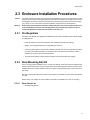
2.3.2
Rack Mounting Rail Kit .....................................................................................................
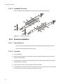
2.3.3
Chassis Installation ..........................................................................................................
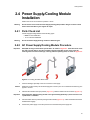
2.4 Power Supply/Cooling Module Installation ................................................................................
2.4.1
Parts Check List ...............................................................................................................
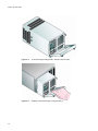
2.4.2
AC Power Supply/Cooling Module Procedure .................................................................
2.4.3
-48V DC Power Supply/Cooling Module Procedure ........................................................
2.5 Controller I/O Module Configurations ........................................................................................
2.5.1
Internal Loop Structures ...................................................................................................
2.6 FC-AL Interface .........................................................................................................................
2.6.1
Connecting Multiple Enclosures .......................................................................................
2.7 Controller I/O Module Installation ..............................................................................................
2.7.1
Parts Check List ...............................................................................................................
2.7.2
Procedure ........................................................................................................................
2.8 Drive Enclosure Device Addressing ..........................................................................................
2.9 Drive Carrier Configuration ......................................................................................................
2.9.1
Planning and Configuring Your Installation ......................................................................
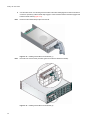
2.10 Drive Carrier Installation ............................................................................................................
2.10.1 Parts Check List ...............................................................................................................
2.10.2 Procedure ........................................................................................................................
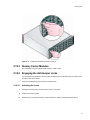
2.10.3 Dummy Carrier Modules ..................................................................................................
2.10.4 Engaging the Anti-tamper Locks ......................................................................................
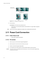
2.11 Power Cord Connection ............................................................................................................
2.11.1 Parts Check List ...............................................................................................................
2.11.2 Procedure ........................................................................................................................
2.12 Grounding Checks ....................................................................................................................
21
21
21
22
23
23
23
24
25
25
25
27
32
32
32
32
33
33
34
35
37
37
37
37
37
39
39
40
40
40
41
3
Operation .......................................................................................................................................
3.1 Before You Begin ......................................................................................................................
3.2 Power On ..................................................................................................................................
3.2.1
Power Supply/Cooling Module LEDs ...............................................................................
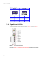
3.3 Ops Panel LEDs ........................................................................................................................
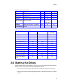
3.4 Starting the Drives .....................................................................................................................
3.4.1
Disk Drives LEDs .............................................................................................................
3.5 Power Down ..............................................................................................................................
43
43
43
43
44
45
46
46
4
RS 232 MUI Functional Description ............................................................................................
4.1 Logical Drive .............................................................................................................................
4.2 Logical Volume ..........................................................................................................................
4.3 RAID Levels ..............................................................................................................................
4.3.1
NRAID ..............................................................................................................................
4.3.2
JBOD ...............................................................................................................................
4.3.3
RAID 0 .............................................................................................................................
4.3.4
RAID 1 .............................................................................................................................
47
47
48
48
49
50
50
50
Contents
4.3.5
RAID (0+1) .......................................................................................................................
4.3.6
RAID 3 ..............................................................................................................................
4.3.7
RAID 5 ..............................................................................................................................
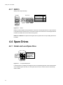
4.4 Spare Drives ..............................................................................................................................
4.4.1
Global and Local Spare Drive ..........................................................................................
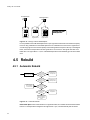
4.5 Rebuild .....................................................................................................................................
4.5.1
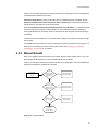
Automatic Rebuild ............................................................................................................
4.5.2
Manual Rebuild ................................................................................................................
4.5.3
Concurrent Rebuild in RAID (0+1) ...................................................................................
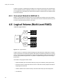
4.6 Logical Volume (Multi-Level RAID) ...........................................................................................
51
51
52
52
52
54
54
55
56
56
5
RAID Planning ...............................................................................................................................
5.1 Considerations ..........................................................................................................................
5.2 Configuring the Array ................................................................................................................
5.2.1
Starting a RAID System ...................................................................................................
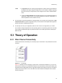
5.3 Theory of Operation ..................................................................................................................
5.3.1
Fibre Channel Connectivity ..............................................................................................
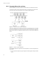
5.3.2
Grouping Drives into an Array ..........................................................................................
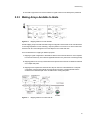
5.3.3
Making Arrays Available to Hosts .....................................................................................
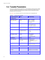
5.4 Tunable Parameters ..................................................................................................................
61
61
64
64
65
65
66
67
68
6
Out-of-Band via Serial Port & Ethernet .......................................................................................
6.1 RS-232 Serial Port ...................................................................................................................
6.1.1
Starting RS232 Terminal Emulation .................................................................................
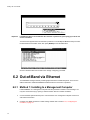
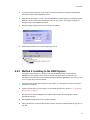
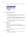
6.2 Out-of-Band via Ethernet ...........................................................................................................
6.2.1
Method 1: Installing to a Management Computer ............................................................
6.2.2
Method 2: Installing to the RAID System ..........................................................................
6.2.3
Connecting Ethernet Port(s) .............................................................................................
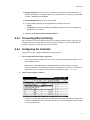
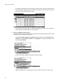
6.2.4
Configuring the Controller ................................................................................................
6.2.5
NPC Onboard ...................................................................................................................
71
71
71
72
72
73
75
75
77
7
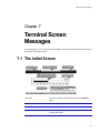
Terminal Screen Messages ..........................................................................................................
7.1 The Initial Screen ......................................................................................................................
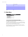
7.2 Main Menu .................................................................................................................................
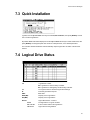
7.3 Quick Installation .......................................................................................................................
7.4 Logical Drive Status ..................................................................................................................
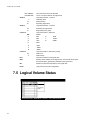
7.5 Logical Volume Status ...............................................................................................................
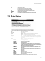
7.6 Drive Status ...............................................................................................................................
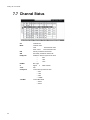
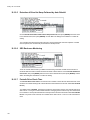
7.7 Channel Status ..........................................................................................................................
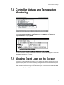
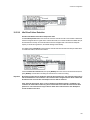
7.8 Controller Voltage and Temperature Monitoring .......................................................................
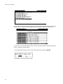
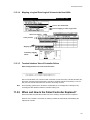
7.9 Viewing Event Logs on the Screen ...........................................................................................
81
81
82
83
83
84
85
86
87
87
8
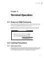
Terminal Operation .......................................................................................................................
8.1 Power on RAID Enclosure .........................................................................................................
8.2 Caching Parameters ..................................................................................................................
8.2.1
Optimization Modes ..........................................................................................................
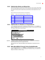
8.2.2
Optimization Mode and Stripe Size ..................................................................................
8.2.3
Optimization for Random or Sequential I/O ......................................................................
8.2.4
Write-Back/Write-Through Cache Enable/Disable ...........................................................
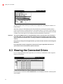
8.3 Viewing the Connected Drives ..................................................................................................
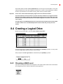
8.4 Creating a Logical Drive ............................................................................................................
89
89
89
89
91
91
91
92
93
v
Galaxy 16m User Guide
8.4.1
Choosing a RAID Level .................................................................................................... 93
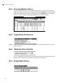
8.4.2
Choosing Member Drives ................................................................................................ 94
8.4.3
Logical Drive Preferences ................................................................................................ 94
8.4.4
Maximum Drive Capacity ................................................................................................ 94
8.4.5
Assign Spare Drives ........................................................................................................ 94
8.4.6
Disk Reserved Space ...................................................................................................... 95
8.4.7
Logical Drive Assignments ............................................................................................... 95
8.4.8
Write Policy ...................................................................................................................... 95
8.4.9
Initialization Mode ............................................................................................................ 96
8.4.10 Stripe Size ........................................................................................................................ 96
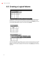
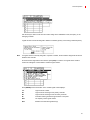
8.5 Creating a Logical Volume ........................................................................................................ 98
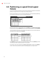
8.6 Partitioning a Logical Drive/Logical Volume ............................................................................ 100
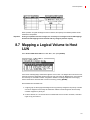
8.7 Mapping a Logical Volume to Host LUN ................................................................................. 101
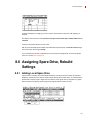
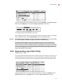
8.8 Assigning Spare Drive, Rebuild Settings ................................................................................ 103
8.8.1
Adding Local Spare Drive .............................................................................................. 103
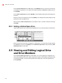
8.8.2
Adding a Global Spare Drive ......................................................................................... 104
8.9 Viewing and Editing Logical Drive and Drive Members .......................................................... 104
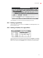
8.9.1
Deleting Logical Drive .................................................................................................... 105
8.9.2
Deleting a Partition of a Logical Drive ............................................................................ 105
8.9.3
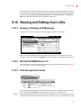
Assigning Logical Drive Name ....................................................................................... 106
8.9.4
Rebuilding Logical Drive ................................................................................................ 106
8.9.5
Regenerating Logical Drive Parity ................................................................................. 107
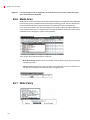
8.9.6
Media Scan .................................................................................................................... 108
8.9.7
Write Policy .................................................................................................................... 108
8.10 Viewing and Editing Host LUNs .............................................................................................. 109
8.10.1 Viewing or Deleting LUN Mappings ............................................................................... 109
8.10.2 Edit Host-ID/WWN Name List ........................................................................................ 109
8.10.3 Pass-through Commands .............................................................................................. 109
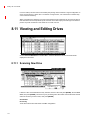
8.11 Viewing and Editing Drives ..................................................................................................... 110
8.11.1 Scanning New Drive ...................................................................................................... 110
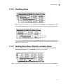
8.11.2 Identifying Drive ............................................................................................................. 111
8.11.3 Deleting Spare Drive (Global/Local Spare Drive) .......................................................... 111
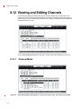
8.12 Viewing and Editing Channels ................................................................................................ 112
8.12.1 Channel Mode ............................................................................................................... 112
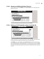
8.12.2 Viewing and Editing IDs/Host Channel .......................................................................... 113
8.12.3 Adding an ID (Primary/Secondary Controller ID) ........................................................... 113
8.12.4 Deleting an ID ................................................................................................................ 114
8.12.5 Setting a Primary Controller SCSI ID/Drive Channel ..................................................... 114
8.12.6 Data Rate ....................................................................................................................... 115
8.13 System Functions .................................................................................................................... 116
8.13.1 Mute Beeper .................................................................................................................. 116
8.13.2 Change Password .......................................................................................................... 116
8.13.3 Changing the Password ................................................................................................. 117
8.13.4 Setting a New Password ................................................................................................ 117
8.13.5 Reset Controller ............................................................................................................. 118
8.13.6 Shutdown Controller ...................................................................................................... 118
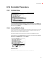
8.14 Controller Parameters ............................................................................................................. 119
8.14.1 Controller Name ............................................................................................................. 119
8.14.2 Saving NVRAM to Disks ................................................................................................ 119
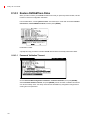
8.14.3 Restore NVRAM from Disks .......................................................................................... 120
8.14.4 Controller Unique Identifier ............................................................................................ 121
vi
Contents
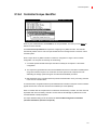
8.14.5 Set Controller Date and Time ......................................................................................... 122
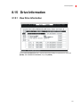
8.15 Drive Information .................................................................................................................... 123
8.15.1 View Drive Information ................................................................................................... 123
9
Fibre Operation ...........................................................................................................................
9.1 Overview .................................................................................................................................
9.2 Major Concerns .......................................................................................................................
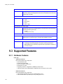
9.3 Supported Features .................................................................................................................
9.3.1
Hardware Features .........................................................................................................
9.3.2
Multiple Target IDs .........................................................................................................
9.3.3
Drive IDs .........................................................................................................................
9.3.4
In-band Fibre Support ....................................................................................................
9.3.5
Redundant Controller Configuration ...............................................................................
9.3.6
Active to Active Redundant Controller ............................................................................
9.3.7
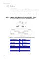
Example: Configuring the Controller 2Gbit Model ..........................................................
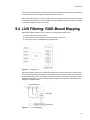
9.4 LUN Filtering: RAID-Based Mapping .......................................................................................
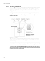
9.4.1
Creating LUN Masks ......................................................................................................
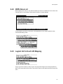
9.4.2
WWN Name List .............................................................................................................
9.4.3
Logical Unit to Host LUN Mapping .................................................................................
9.4.4
LUN Mask (ID Range) Configuration ..............................................................................
9.4.5
Filter Type: Include or Exclude .......................................................................................
9.4.6
Access Mode: Read Only or Read/Write ........................................................................
9.4.7
Sample Configuration: ....................................................................................................
125
125
125
126
126
127
127
127
127
127
128
129
130
131
131
133
134
134
135
10 Advanced Configuration ............................................................................................................
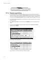
10.1 RAID Expansion ......................................................................................................................
10.1.1 Logical Drive Expansion .................................................................................................
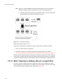
10.1.2 Mode 1 Expansion: Adding a Drive to a Logical Drive ...................................................
10.1.3 Mode 2 Expansion: Copy and Replace Drives with Drives of Larger Capacity ..............
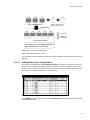
10.1.4 Expand Logical Drive .....................................................................................................
10.1.5 Expand Logical Volume ..................................................................................................
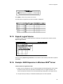
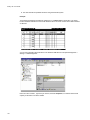
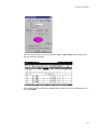
10.1.6 Example: RAID Expansion in Windows 2000® Server ..................................................
10.2 Fault Prevention ......................................................................................................................
10.2.1 Clone Failing Drive .........................................................................................................
10.2.2 SMART (Self-Monitoring, Analysis and Reporting Technology) .....................................
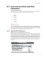
10.3 Host-side and Drive-side SCSI Parameters ............................................................................
10.3.1 Host-side SCSI Parameters ...........................................................................................
10.3.2 Drive-side Parameters ....................................................................................................
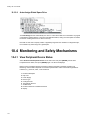
10.4 Monitoring and Safety Mechanisms ........................................................................................
10.4.1 View Peripheral Device Status .......................................................................................
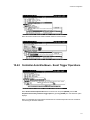
10.4.2 Controller Auto-Shutdown - Event Trigger Operations ...................................................
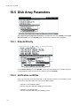
10.5 Disk Array Parameters ............................................................................................................
10.5.1 Rebuild Priority ...............................................................................................................
10.5.2 Verification on Writes .....................................................................................................
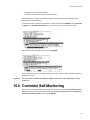
10.6 Controller Self-Monitoring ........................................................................................................
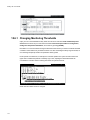
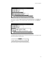
10.6.1 Changing Monitoring Thresholds ...................................................................................
137
137
137
138
141
144
145
145
151
151
154
159
159
165
170
170
171
172
172
172
173
174
11 Redundant Controller .................................................................................................................
11.1 Operation Theory ....................................................................................................................
11.1.1 Setup Flowchart .............................................................................................................
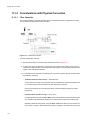
11.1.2 Considerations with Physical Connection ......................................................................
177
177
177
178
vii
Galaxy 16m User Guide
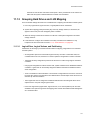
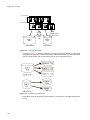
11.1.3 Grouping Hard Drives and LUN Mapping ......................................................................
11.1.4 Fault Tolerance ..............................................................................................................
11.2 Preparing Controllers ..............................................................................................................
11.2.1 Requirements .................................................................................................................
11.2.2 Limitations ......................................................................................................................
11.2.3 Configurable Parameters ...............................................................................................
11.3 Configuration ...........................................................................................................................
11.3.1 Via Terminal Emulation ..................................................................................................
11.3.2 When and How Is the Failed Controller Replaced? .......................................................
179
182
187
187
188
188
189
190
193
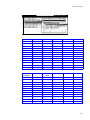
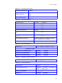
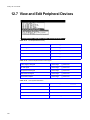
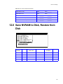
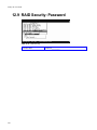
12 Record of Settings ......................................................................................................................
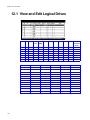
12.1 View and Edit Logical Drives ...................................................................................................
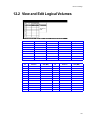
12.2 View and Edit Logical Volumes ...............................................................................................
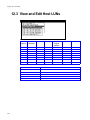
12.3 View and Edit Host LUNs ........................................................................................................
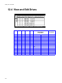
12.4 View and Edit Drives ...............................................................................................................
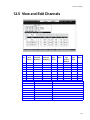
12.5 View and Edit Channels ..........................................................................................................
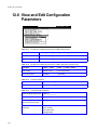
12.6 View and Edit Configuration Parameters ................................................................................
12.7 View and Edit Peripheral Devices ...........................................................................................
12.8 Save NVRAM to Disk, Restore from Disk ...............................................................................
12.9 RAID Security: Password ........................................................................................................
197
198
199
200
202
203
204
206
207
208
13 Troubleshooting and Problem Solving .....................................................................................
13.1 Overview .................................................................................................................................
13.1.1 Emulation Limitations .....................................................................................................
13.1.2 Initial Start-up Problems .................................................................................................
13.2 LEDs .......................................................................................................................................
13.2.1 Power Supply/Cooling Module .......................................................................................
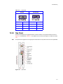
13.2.2 Ops Panel ......................................................................................................................
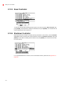
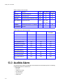
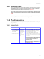
13.3 Audible Alarm ..........................................................................................................................
13.3.1 Audible Alarm Mute ........................................................................................................
13.4 Troubleshooting ......................................................................................................................
13.4.1 System Faults ................................................................................................................
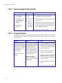
13.4.2 Power Supply/Cooling Faults .........................................................................................
13.4.3 Thermal Control .............................................................................................................
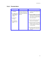
13.4.4 Thermal Alarm ...............................................................................................................
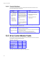
13.4.5 Thermal Shutdown .........................................................................................................
13.5 Drive Carrier Module Faults ....................................................................................................
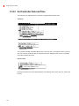
13.5.1 Dummy Carrier Modules ...............................................................................................
13.5.2 Auto Start Failure ...........................................................................................................
13.6 Dealing with Hardware Faults .................................................................................................
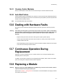
13.7 Continuous Operation During Replacement ...........................................................................
13.8 Replacing a Module ................................................................................................................
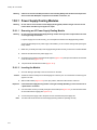
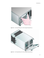
13.8.1 Power Supply/Cooling Modules .....................................................................................
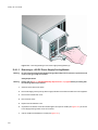
13.8.2 Ops Panel ......................................................................................................................
13.8.3 Controller I/O Module .....................................................................................................
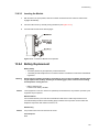
13.8.4 Battery Replacement .....................................................................................................
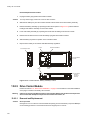
13.8.5 Drive Carrier Module ......................................................................................................
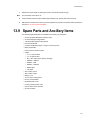
13.9 Spare Parts and Ancillary Items .............................................................................................
209
209
209
209
210
210
211
212
213
213
213
214
214
215
216
216
217
217
217
217
217
218
223
223
225
226
227
A System Functions: Upgrading Firmware .................................................................................. 229
A.1 Upgrading Firmware ................................................................................................................ 229
viii
Contents
A.2 New Features Supported with Firmware 3.21 .........................................................................
A.2.1 Background RS-232 Firmware Download ......................................................................
A.2.2 Redundant Controller Rolling Firmware Upgrade ..........................................................
A.2.3 Redundant Controller Firmware Sync-version ...............................................................
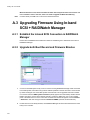
A.3 Upgrading Firmware Using In-band SCSI + RAIDWatch Manager .........................................
A.3.1 Establish the In-band SCSI Connection in RAIDWatch Manager ..................................
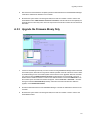
A.3.2 Upgrade both Boot Record and Firmware Binaries ........................................................
A.3.3 Upgrade the Firmware Binary Only ................................................................................
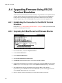
A.4 Upgrading Firmware Using RS-232 Terminal Emulation ........................................................
A.4.1 Establishing the Connection for the RS-232 Terminal Emulation ..................................
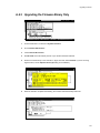
A.4.2 Upgrading both Boot Record and Firmware Binaries .....................................................
A.4.3 Upgrading the Firmware Binary Only .............................................................................
229
229
229
229
230
230
230
231
232
232
232
233
B Event Messages ..........................................................................................................................
B.1 Event Index .............................................................................................................................
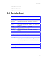
B.1.1 Controller Event ..............................................................................................................
B.1.2 Drive SCSI Channel/Drive Error .....................................................................................
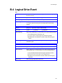
B.1.3 Logical Drive Event ........................................................................................................
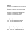
B.1.4 General Target Events ...................................................................................................
B.2 Controller Event .......................................................................................................................
B.3 Drive SCSI Channel/Drive Error ..............................................................................................
B.4 Logical Drive Event .................................................................................................................
B.5 General Target Events ............................................................................................................
235
235
235
236
238
239
241
243
249
253
Glossary .............................................................................................................................................. 263
Index ................................................................................................................................................... 265
ix
Galaxy 16m User Guide
x
Preface
Preface
What is in this guide
This user guide gives you step-by-step instructions on how to install, configure and connect a Galaxy 16m
RAID Controller storage subsystem to your host computer system, and how to use and maintain the
system. It also provides all of the necessary information that a system administrator needs to configure
and maintain the RAID controllers, utilizing the RS232 Management User Interface (MUI)).
Who should use this guide
This user guide assumes that you have a working knowledge of the Fibre Channel Arbitrated Loop (FCAL) and Advanced Technology Attachment (ATA) environments into which you are installing the Galaxy
16m system. If you do not have these skills, or are not confident with the instructions in this guide, do not
proceed with the installation.
About this guide
This user guide provides the following information:
• Chapter 1, ”Introduction”, on page 1 provides an overview of the Galaxy 16m storage subsystem
and describes of the modules which make up the subsystem.
• Chapter 2, ”Getting Started”, on page 21 provides step-by-step instructions for installation and initial
set-up.
• Chapter 3, ”Operation”, on page 43 tells you how to power on/off the Galaxy 16m, monitor the LEDs
and start the drives.
• Chapter 4, ”RS 232 MUI Functional Description”, on page 47 introduces the RS232 MUI and RAID,
describing the functions of RAID levels, logical drives, spare drives, and logical volumes
• Chapter 5 , ”RAID Planning”, on page 61 introduces basic RAID concepts and configurations,
including RAID levels, logical drives, spare drives, and logical volumes. It is recommended that
users unfamiliar with RAID technologies should read this chapter before creating a configuration.
• Chapter 6, ”Out-of-Band via Serial Port & Ethernet”, on page 71 tells you how to begin with a RAID.
At the beginning of this chapter, we raise some basic questions of which the user should know the
answers prior to creating a RAID.
• Chapter 7 , ”Terminal Screen Messages”, on page 81 teaches you how to configure the RS-232C
terminal emulation interface and the connection through a LAN port.
• Chapter 8, ”Terminal Operation”, on page 89 teaches you how to interpret the information found on
the RS-232 terminal emulation.
• Chapter 9 , ”Fibre Operation”, on page 125 gives step-by-step instructions on how to create a RAID
via the RS-232 terminal.
• Chapter 10, ”Advanced Configuration”, on page 137 includes all the Fibre-specific functions
implemented since the firmware release 3.12.
• Chapter 11 , ”Redundant Controller”, on page 177 provides the advanced options for RAID
configuration.
xi
Galaxy 16m User Guide
• Chapter 12, ”Record of Settings”, on page 197 addresses the concerns regarding the redundant
controller configuration and the configuration process.
• Chapter 13, ”Troubleshooting and Problem Solving”, on page 209 provides help and guidance on
troubleshooting and problem solving.
• Appendix A, ”System Functions: Upgrading Firmware”, on page 229 teaches you how to upgrade
firmware and boot record.
• Appendix B , ”Event Messages”, on page 235 lists all of the controller event messages.
• , ”Glossary”, on page 263 defines common terms used throughout this user guide.
International Standards
The Galaxy 16m storage system complies with the requirements of the following agencies and standards:
• CE to IEC 950/EN60950
• UL 60950
• cUL
Potential for Radio Frequency
Interference
USA Federal Communications Commission (FCC)
Note
This equipment has been tested and found to comply with the limits for a class A digital device, pursuant
to Part 15 of the FCC rules. These limits are designed to provide reasonable protection against harmful
interference when the equipment is operated in a commercial environment. This equipment generates,
uses and can radiate radio frequency energy and, if not installed and used in accordance with the
instruction manual, may cause harmful interference to radio communications. Operation of this
equipment in a residential area is likely to cause harmful interference in which case the user will be
required to correct the interference at his own expense.
Properly shielded and grounded cables and connectors must be used in order to meet FCC emission
limits. The supplier is not responsible for any radio or television interference caused by using other than
recommended cables and connectors or by unauthorized changes or modifications to this equipment.
Unauthorized changes or modifications could void the user’s authority to operate the equipment.
This device complies with Part 15 of the FCC Rules. Operation is subject to the following two conditions:
(1) this device may not cause harmful interference, and (2) this device must accept any interference
received, including interference that may cause undesired operation.
xii
Preface
European Regulations
This equipment complies with European Regulations EN 55022 Class A: Limits and Methods of
Measurement of Radio Disturbance Characteristics of Information Technology Equipments and
EN50082-1: Generic Immunity.
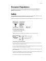
Safety
All plug-in modules are part of the fire enclosure and must only be removed when a replacement can be
immediately added. The system must not be run without all units in place.
Permanently unplug the unit if you think that it has become damaged in any way and before you move it.
Drive Carrier Module Caution Label:
– Do not operate with modules missing
– Spin down time 30 seconds
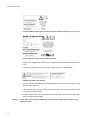
• A Galaxy 16m enclosure can weigh up to 37kg (81lb). Do not try to lift it by yourself.
Chassis Warning Label: Weight Hazard
• Do not lift the Galaxy 16m by the handles on the PSU/Cooling module, they are not designed to
support the weight of the populated enclosure.
• In order to comply with applicable safety, emission and thermal requirements no covers should be
removed and all bays must be fitted with plug-in modules.
• The Galaxy 16m unit must only be operated from a power supply input voltage range of 100 - 120
VAC or 200-240 VAC.
• The plug on the power supply cord is used as the main disconnect device. Ensure that the socket
outlets are located near the equipment and are easily accessible.
• The equipment is intended to operate with two working PSUs.
xiii
Galaxy 16m User Guide
Controller Module Caution Label: Do not operate with modules missingPSU/Cooling Module
Caution Label: Do not operate with modules missing
• A faulty Power Supply/Cooling module must be replaced with a fully operational module within 24
hours.
• If powered by multiple AC sources, disconnect all supply power for complete isolation.
PSU Warning Label: Power Hazards
• The power connection should always be disconnected prior to removal of the Power Supply/Cooling
module from the enclosure.
• A safe electrical earth connection must be provided to the power cord. Check the grounding of the
enclosure before applying power.
• Provide a suitable power source with electrical overload protection to meet the requirements laid
down in the technical specification.
Warning
xiv
Do not remove covers from the PSU. Danger of electric shock inside. Return the PSU to your
supplier for repair.
Preface
PSU Safety Label: Electric Shock Hazard Inside
Caution
If this equipment is used in a manner not specified by the manufacturer, the protection provided by the
equipment may be impaired.
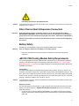
Fibre Channel Host & Expansion Connectors
Important
If fitted with Optical modules, the modules must be a UL (or other North American NRTL)
RECOGNISED COMPONENT, must be approved by TUV (or other European Product Safety test
house) and the laser in the module must comply with Laser Class 1, US 21 CFR (J) and EN 60825-1
If passive copper cables are connected, the cable must not have a connection to the supply pins,
pins 15 & 16.
Battery Safety
The battery is user replaceable, please refer to the Battery Replacement Procedure.
Warning
There is a danger of explosion if the battery is incorrectly replaced.
• Dispose of used batteries in accordance with the manufacturer’s instructions and National
regulations.
-48V DC PSU/Cooling Module Safety Requirements
The following paragraphs summarize additional safety requirements to be observed when installing or
operating a -48V DC Power Supply/Cooling module: Please refer to section 2.4.3.1, ”-48V DC PSU
Safety Requirements”, on page 28 for full details of European and North American safety requirements
applicable to this module.
Voltage Rating
The marked rated voltage for the-48VDC Power Supply/Cooling module is -40V DC to -60V DC. The
equipment is intended to operate from a centralized dc supply system with a NOMINAL voltage of -48V
DC or -60V DC.The voltage from a nominal -48V DC system may vary, due to float charging or discharge
conditions, from -40V DC to -60V DC.The voltage from a nominal -60V DC system may vary, due to float
charging or discharge conditions, from -48V DC to -72V DC.
Caution
If this equipment is used in a manner not specified by the manufacturer, the protection provided by the
equipment may be impaired.
Equipment Location
The rear of this Equipment (in particular the supply terminals and wiring to the terminals on the power
supply) must only be located in a “RESTRICTED ACCESS LOCATION” where both of the following
apply (Ref.UL60950):
• access can only be gained by SERVICE PERSONNEL or by USERS who have been instructed
about the reasons for the restrictions applied to the location and about any precautions that shall be
taken; and
xv
Galaxy 16m User Guide
• access is through the use of a TOOL or lock and key, or other means of security and is controlled
by the authority responsible for the location.
Disconnect Device
The wiring installation must provide a disconnect device close to the product.
Wiring
Must be connected in accordance with the local and National wiring regulations.
Wire Temperature Rating
The supply wiring to the power supply terminal blocks must have a minimum temperature rating of
75ºC.mu
Circuit Protection
The building installation must provide overcurrent and short circuit protection in the non earthed supply
conductor.
-48V DC PSU: USA and Canadian Safety Requirements
Wiring Methods
Wiring method must be code compliant in the field.
Wiring methods must be in accordance with the U.S. National Electric Code, Article 300.
Earthing
This equipment is designed to permit the connection of the earthed conductor (+) of the dc supply circuit
to the earthing conductor at the equipment.
Protective Earth Conductor Size
The protective earth conductor size must be suitable for the maximum fault current that the installation
can provide. U.S. National Electric Code, Article 250-122
Branch Circuit Protection
The PSU must be connected to a Branch circuit that is protected by a LISTED Branch Protector. The
rating of the LISTED Branch Protector >= 125% of the product rating and the rating of the LISTED Branch
Protector =< current rating of wire supplying the equipment. U.S. National Electric Code, Article 210-3,
Article 240.
Rack System Precautions
The following safety requirements must be considered when the unit is mounted in a rack.
• The rack design should incorporate stabilizing features suitable to prevent the rack from tipping or
being pushed over during installation or in normal use.
• When loading a rack with the units, fill the rack from the bottom up and empty from the top down.
• System must be operated with low pressure rear exhaust installation (Back pressure created by rack
doors and obstacles not to exceed 5 pascals [0.5mm Water gauge])
xvi
Preface
• The rack design should take into consideration the maximum operating ambient temperature for the
unit, which is 35°C with a single Power Supply/Cooling module fitted and 40°C when dual Power
Supply/Cooling modules are fitted.
• The rack should have a safe electrical distribution system. It must provide overcurrent protection for
the unit and must not be overloaded by the total number of units installed in the rack. Consideration
of the units nameplate rating should be used when addressing these concerns.
• The electrical distribution system must provide a reliable earth for each unit and the rack.
• Each power supply in each unit has an earth leakage current of 1.2mA. The design of the electrical
distribution system must take into consideration the total earth leakage current from all the power
supplies in all the units. The rack will require labelling with "HIGH LEAKAGE CURRENT. Earth
connection essential before connecting supply".
• The rack when configured with the units must meet the safety requirements of UL 60950 and IEC
60950.
ESD Precautions
Caution
It is recommended that you fit and check a suitable anti-static wrist or ankle strap and observe all
conventional ESD precautions when handling Galaxy 16m plug-in modules and components. Avoid
contact with backplane components and module connectors, etc.
Data Security
• Power down your host computer and all attached peripheral devices before beginning installation.
• Each enclosure contains up to 16 removable disk drive modules. Disk units are fragile. Handle them
with care, and keep them away from strong magnetic fields.
• All the supplied plug-in modules and blanking plates must be in place for the air to flow correctly
around the enclosure and also to complete the internal circuitry.
• If the subsystem is used with modules or blanking plates missing for more than a few minutes, the
enclosure can overheat, causing power failure and data loss. Such use may also invalidate the
warranty.
• If you remove any drive module, you may lose data.
– If you remove a drive module, replace it immediately. If it is faulty, replace it with a drive module
of the same type and capacity
• Ensure that all disk drives are removed from the enclosure before attempting to manhandle or move
the rack installation.
• Do not abandon your backup routines. No system is completely foolproof.
xvii
Galaxy 16m User Guide
Special Tools and Equipment
There are no special tools required but in order to complete the assembly of some configurations you may
need the following (not supplied):
• Security keys (one of these should be included with your Galaxy 16m enclosure for use with the drive
locks).
Related Documentation
• Galaxy 16m Quick Installation Guide (P/N 36216-01)
• RS-Salient Series Rack Installation Guide (P/N 43638-02)
• RAIDwatch User Guide (P/N 45374-01)
Revision History
xviii
Version
Date
Description of Change
1.0
November, 2003
Initial Release
Introduction
Chapter 1
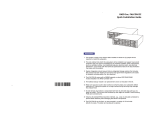
Introduction
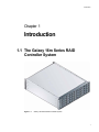
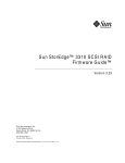
1.1 The Galaxy 16m Series RAID
Controller System
.
Figure 1–1
Galaxy 16m Series RAID Controller System
1
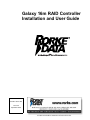
Galaxy 16m User Guide
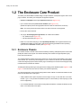
1.2 The Enclosure Core Product
The Galaxy 16m Series RAID Controller design concept is based on a subsystem together with a set of
plug-in modules. The Galaxy 16m subsystem as supplied comprises:
• Chassis and Backplane with integral Operators Panel.(See Figure 1–10)
• Up to 16 Serial ATA (SATA) Drive Carrier modules (See Figure 1–12)
(Parallel ATA (PATA) drives with appropriate transition cards for SATA-PATA conversion)
Note: The mixing of SATA and PATA drives in the same enclosure is not supported.
• Dummy drive carrier modules.
• Two plug-in Power Supply/Cooling modules, two variants are available:
– .AC, 450W PSU (see Figure 1–5)
– -48V DC 450W PSU (see Figure 1–6)
• Either one or two Serial ATA plug-in LRC Input/Output Modules, with integrated Infortrend IFT1728RMN SATA RAID controllers and 1.5Gb internal operating speed/2Gb external operating
speed, known as Controller modules. (See Figure 1–8).
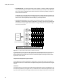
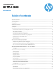
1.2.1 Enclosure Chassis
The chassis consists of a sheet metal enclosure assembly containing a Backplane printed circuit board
(PCB) and module runner system This chassis assembly also includes an integral Operators (Ops)
Panel, mounted at the rear.
The chassis assembly contains 16 drive bays at the front, each of which accommodates a plug-in drive
carrier module. The 16 drive bays are arranged in 4 rows of 4 drives. At the rear, the chassis assembly
contains the integral ops panel module and four plug-in module bays to house two Power Supply/Cooling
modules and two Controller I/O modules.
The Backplane PCB provides logic level signal and low voltage power distribution paths. Figure 1–2 and
Figure 1–3 show front and rear views of a Galaxy 16m chassis respectively.
The chassis is fitted with 19 inch Rack mounting features which enables it to be fitted to standard 19 inch
racks and uses 3EIA units of rack space.
• A Bay is defined as the space required to house a single 1.0" high 3.5 inch disk drive in its carrier
module. e.g. a 1 x 4 bay module would take the space of 1 drive width by 4 drive bays high (in rack
mount configuration).
• A 4 x 4 Chassis fitted with 19 inch Rack mounting features enables it to be fitted to standard 19 inch
racks. It uses 3EIA units of rack space
2
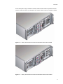
Introduction
.
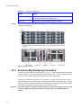
Figure 1–2
Enclosure Chassis (Front)
Figure 1–3
Enclosure Chassis (Rear)
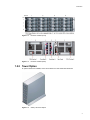
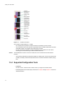
1.2.2 Tower Option
An optional tower kit is available, which can be fitted to the rack chassis described here.
Figure 1–4
Galaxy 16m Tower Option
3
Galaxy 16m User Guide
1.3 The Plug-in Modules
A Galaxy 16m Enclosure requires the following modules for normal operation:
• 2 x Power Supply/Cooling modules
• 1 x Operator Panel
• 2 x Controller I/O modules
• Up to 16 SATA drive carrier modules and/or dummy drive carrier modules, as required.
Note
No drive bays should be left completely empty.
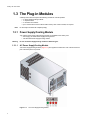
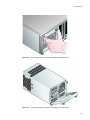
1.3.1 Power Supply/Cooling Module
Two variants of the Power Supply/Cooling module are available for the Galaxy 16m:
• Auto ranging AC 450W Power Supply/Cooling module
• -48V DC 450W Power Supply/Cooling module
Warning
Do not mix Power Supply/Cooling modules of different types.
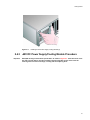
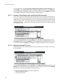
1.3.1.1
AC Power Supply/Cooling Module
Two Power Supply/Cooling modules (Figure 1–5) are supplied mounted in the rear of the enclosure as
part of the subsystem core product.
Figure 1–5
4
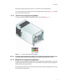
AC Power Supply/Cooling Module
Introduction
PSU voltage operating ranges are nominally 115V or 230V AC, selected automatically.
.
Four LEDs mounted on the front panel of the Power Supply/Cooling module (see Figure 2–1) indicate
the status of the PSU and the fans.
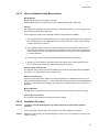
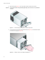
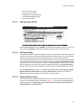
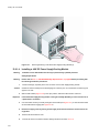
1.3.1.2
-48V DC Power Supply/Cooling Module
A -48V DC Input Power Supply/Cooling Module variant is also available (Figure 1–6).
Figure 1–6
-48V DC Power Supply/Cooling Module
Warning
The -48V DC Power Supply/Cooling module is not an operator removable part. It should only be
removed by a technician who has knowledge of the hazards present within the module.
1.3.1.3
Multiple Power Supply/Cooling Modules
The Galaxy 16m must always be operated with two Power Supply/Cooling modules fitted. The two Power
Supply/Cooling modules operate together so that if one fails the other maintains the power supply and
cooling while you replace the faulty unit.
Module replacement should only take a few minutes to perform but must be completed within 10 minutes
from removal of the failed module.
5
Galaxy 16m User Guide
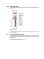
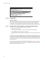
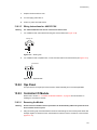
1.3.2 Operators Panel
Supplied as an integral part of the Enclosure core product, a typical Operators (Ops) Panel is shown in
Figure 1–7.
Figure 1–7
Ops Panel
The Ops Panel provides the enclosure with a micro controller which is used to monitor and control all
elements of the Enclosure.
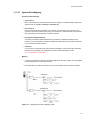
1.3.2.1
Ops Panel Indicators and Switches
The Ops Panel includes Light Emitting Diodes (LEDs) which show the status for all modules, an Audible
Alarm which indicates when a fault state is present, a push-button Alarm Mute Switch and a thumb wheel
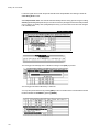
Enclosure ID switch.
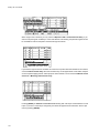
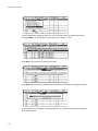
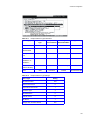
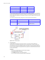
The Ops Panel switch functions are shown in Table 1–1.
6
Introduction
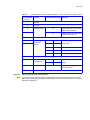
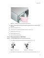
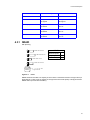
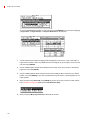
Table 1–1
Ops Panel Switch Functions (Default settings for Galaxy 16m Controller usage at 2Gb/s)
Switch Number Function
*See Sw 11
1
Not Used
2
Not Used
3
Hub Mode Select
4
5&6
Important
Note
Recommended Setting
Definition
On
Enable: RAID host FC ports will be
linked together internally.
Off
Disable: RAID host FC ports will be
independently connected.
Not Used
RAID host hub
speed select
switches
7&8
Not Used
9 & 10
Drive Addressing
Mode Selection
11
SOFT SELECT
12
Not Used
Sw5 5
Sw 6
Off
Off
Force 1Gb/s
On
Off
Force 2Gb/s
Off
On
Auto
On
On
Auto
Sw 9
Sw 10
On
On
On
Mode 0
Select functions using the
hardware switches.
Switch settings are only read at Power On.
When using host side multi-pathing/fail over software that does not dynamically discover of new data
paths and no external switch is present, Hub Mode will be required. Hub Mode may also be required in
alternative configurations.
7
Galaxy 16m User Guide
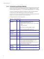
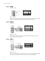
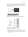
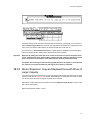
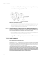
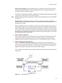
1.3.3 Controller Input/Output Module
The Galaxy 16m storage subsystem includes an enclosure with rear facing bays which houses two Loop
Resiliency Circuit (LRC) I/O modules with integrated Infortrend IFT-1728RMN SATA RAID controllers,
known as Controller modules (see Figure 1–3). The controller supports RAID levels 0, 1, 3, 5, 10 and 50.
The plug-in I/O modules have been designed for integration into a Galaxy 16m storage subsystem,
providing external FCAL cable interfacing with up to 16 SATA or PATA disk drives.
Processors housed on the I/O modules provide enclosure management and interface to devices on the
Backplane, PSU, Controller and Ops Panel, to monitor internal functions.
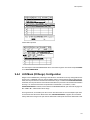
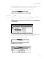
The module incorporates the following LED indicators:
Table 1–2
Controller Module LEDs
LED Functions
Color
Description
Battery Fail
Amber
When ON this LED denotes the following status:
• Battery voltage is lower than 2.5V.
• Battery temperature is abnormal (normal 0° - 45°C on charge
state)
• BBU is NOT present
When FLASHING, the LED denotes BBU is charging.
When OFF, the LED denotes BBU charge is done.
8
Expansion Port
Signal Good
Green
When ON this LED denotes that running FC signal is good.
RJ45 Ethernet
Connection
Green
LED1: Static ON while LAN port status is link.
Green
LED2: FLASHING while LAN port status is active.
System
Amber
When ON this LED denotes that the Controller is failed or CEMI card
is failed.
Cache Active
Amber
When ON this LED denotes the following status:
• When system is with power, ON denotes cache memory
contains data or ECC errors are detected.
• When system is without power, ON denotes cache memory
contains data and is held up by BBU.
This LED is local to each controller.
Host Port 1
Signal Good
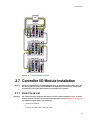
Green
When ON this LED denotes that incoming FC signal is GOOD.
Host port 0
Signal Good
Green
When ON this LED denotes that incoming FC signal is GOOD.
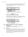
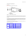
Introduction
Figure 1–8
Important
Controller I/O Module
Fitting of a RAID controller to the LRC module is a factory only operation.
9
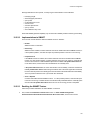
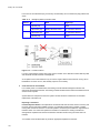
Galaxy 16m User Guide
Figure 1–9
Controller Front Panel
The Controller module operates at 1 or 2 Gb/s.
• One external port for expansion to further enclosures is provided by an SFP connector
• Two external ports to the host controllers are provided from the Controller module with Form Factor
(SFP) GBIC modules, auto-bypass at the output ports is provided.
• An RJ45 10/100 Base T Ethernet controller management port is provided on the LRC board,
interfacing to the controller through 2 RS232 serial and GPIO lines.
Caution
The RJ45 Ethernet connector on the LRC module must not be connected to telecommunications
networks.
• The Controller module also incorporates a standby Li-ion battery pack, 72 hours cache hold up time
(512Mb). The battery cell has thermal protection and is connected to the RAID controller by flying
lead.
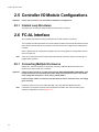
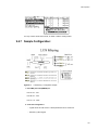
1.3.4 Supported Configuration Tools
• RAIDWatch:
Firmware version: 3.27d2 and above: Please contact your supplier for the latest release.
• R232 Management User Interface (MUI). Please refer to Chapter 4 through Chapter 12 inclusive for
detailed information.
10
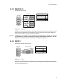
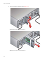
Introduction
The RS-1600 product range is available in 1Gb/2Gb, JBOD or RAID variants for operation with Fibre
Channel or Serial ATA drives, by changing the LRC modules. Please contact your supplier for details
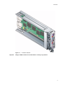
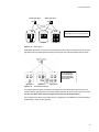
Figure 1–10
Galaxy 16m Enclosure with Controller I/O Modules and AC PSUs Installed
Figure 1–11
Galaxy 16m Enclosure with Controller I/O Modules and DC PSUs Installed
11
Galaxy 16m User Guide
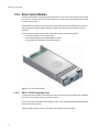
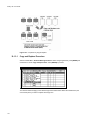
1.3.5 Drive Carrier Module
The Drive Carrier Module comprises a hard disk mounted in a carrier. Each drive bay will house a single
Low Profile 1.0 inch high, 3.5 inch form factor disk drive in its carrier.The carrier has mounting locations
for ATA or FC-AL drives.
Each disk drive is enclosed in a die-cast aluminum carrier which provides excellent thermal conduction,
radio frequency and electro-magnetic induction protection and affords the drive maximum physical
protection.
The front cap also supports an ergonomic handle which provides the following functions:
• Camming of carrier into and out of drive bays.
• Positive 'spring loading' of the drive/backplane connector.
• An anti-tamper lock operated by a torx socket type key.
Figure 1–12
1.3.5.1
Drive Carrier Module
SATA - PATA Transition Card
For Serial ATA use a Transition card is attached to the rear of each drive, this provides a SCA-2 interface
to the drive carrier using the same pins as Fibre Channel.
There are two types of Transition card providing 1.5 Gb/s, one for standard Parallel ATA disk drives and
the other for Serial ATA drives.
Transition cards provide two paths to each drive, thus improving system availability.
12
Introduction
1.3.5.2
Drive Status Indicators
Each drive carrier incorporates two indicators, an upper (Green) and lower (Amber). In normal operation
the green indicator will be ON and will flicker as the drive operates. The amber indicator is OFF in normal
operation and ON when there is a fault present.
Note
1.3.5.3
In some access configurations with PATA drives the light will not flicker. This is normal behavior for this
product.
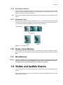
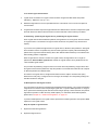
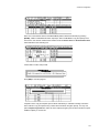
Anti-tamper Locks
Anti-tamper locks are fitted in the drive carrier handles (Figure 1–13) and are accessed through the small
cutout in the latch section of the handle.These are provided to disable the normal ‘pinch' latch action of
the carrier handle and prevent accidental or unauthorized removal of drives.
Figure 1–13
Anti-tamper Lock
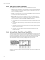
1.3.6 Dummy Carrier Modules
Dummy carrier modules are provided for fitting in all unused drive bays. They are designed as integral
drive module front caps with handles and must be fitted to all unused drive bays to maintain a balanced
airflow.
1.3.7 Blank Modules
Warning
Operation of the Enclosure with ANY modules missing will disrupt the airflow and the drives will
not receive sufficient cooling. It is ESSENTIAL that all apertures are filled before operating the
unit. Dummy Carriers and/or Blank modules are available for this purpose.
1.4 Visible and Audible Alarms
The functional modules have associated status LEDs. The Ops Panel shows a consolidated status for all
modules.
LEDs show constant green for good or positive indication. Constant Amber LEDs indicate there is a fault
present within that module.
13
Galaxy 16m User Guide
The Ops Panel also incorporates an Audible Alarm to indicate when a fault state is present and also an
Alarm Mute push-button.
Warning
The Ops Panel is an integral part of the enclosure chassis assembly and is not field replaceable.
1.5 Galaxy 16m Technical Specification
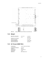
1.5.1 Dimensions
Rack Enclosure
millimeters
Height
5.1
130
Width across mounting flange
19
483
Width across body of enclosure
17.6
447
21
531
Depth from flange to maximum extremity of enclosure (rear hold down)
21.7
550
Depth from flange to furthest extremity at front of unit
0.5
13
Depth overall
22.2
563
Depth from flange to rear of enclosure body
Tower Enclosure
14
inches
inches
millimeters
Height
22.27
501
Width (including mounting feet)
10.22
230
Depth
23.24
523
Introduction
Table 1–3
Galaxy 16m Series RAID Controller Chassis Dimensions
1.5.2 Weight
Maximum Configuration
Rack mount:
Tower:
37kg (81lb)
40kg (88lb)
Empty Enclosure (Rack)
9kg (19.8lb)
PSU/Cooling Module
4kg (8.8lb)
Controller I/O Module
0.9kg (1.98lb)
Tower Conversion Kit
3kg (6.6lb)
1.5.3 AC Power (450W PSU)
Voltage Range
100-120 / 200-240 VAC Rated
Voltage Range Selection
Automatic
Frequency
50/60 Hz
Inrush Current
50A @ 260VAC
Power Factor
>0.98
Harmonics
Meets EN61000-3-2
15
Galaxy 16m User Guide
1.5.4 -48V DC Power (450W PSU)
DC Input Voltage Range
-40V to -60V DC Rated
DC Line Inrush Current
50A peak
1.5.5 PSU Safety and EMC Compliance
Safety Compliance
UL 60950
IEC 60950
EN 60950
EMC Compliance
CFR47 Part 15B Class A
EN55022
EN55024
1.5.6 Power Cord
(minimum requirements)
Cord Type
SV 0r SVT, 18 AWG minimum, 3 conductor
Plug
250V, 10A
Socket
IEC 320 C-14, 250V, 15A
1.5.7 Environment
Table 1–4
Ambient Temperature and Humidity
Temperature Range
Operational
5°C to 40°C
Relative Humidity
Max. Wet Bulb
20% to 80%
23°C
non-condensing
Non-Operational
0°C to +50°C
8% to 80%
27°C
non-condensing
Storage
1°C to +60°C
8% to 80%
29°C
non-condensing
Shipping
-40°C to +60°C
5% to 100%
non-precipitating
16
29°C
Introduction
Airflow
System must be operated with low pressure rear exhaust installation
(Back pressure created by rack doors and obstacles not to exceed 5
pascals [0.5mm Water gauge])
Altitude, Operational
0 to 2000 m (0 to 7,000ft)
(10,000ft at maximum ambient of 35°C)
Altitude, Non-Operational
-305 to 12,192m (-1000 to 40,000ft)
Shock, Operational
Vertical axis 5g peak 1/2 sine, 10ms
Shock, Non-Operational
30g 10ms 1/2 sine
Vibration, Operational
0.21grms 5-500 Hz Random
Vibration, Non-Operational
1.04grms 2-200 Hz Random
Vibration, Relocation
0.3g 2-200 Hz sine
Acoustics
Sound Pressure Operating - Less than 58 dB LpA average
measured at the bystander positions.
(The 4 bystander positions are 1m horizontal and 1.5m off the floor
positioned front, back, left and right. The unit under test will be
measured on the floor)
Measured at 20°C
Orientation & Mounting
19" Rack mount (3EIA Units)
• Rack Rails
To fit 800mm depth Racks compliant with IEC 297
• Rack Characteristics
Back pressure not exceeding 5 pascals (0.5mm water gauge)
Safety & Approvals
• EMC
CE, UL, cUL
EN55022 (CISPR - A), FCC A
1.5.8 Interfaces
Drive support See drive carrier specification
Attachment
• 1 FCAL loop of 16 drives
• Passive Backplane with 1 Loop Resiliency Circuit (Controller) I/O Module.
Host Port: FC-AL
– 2 x SFP optical
Expansion Port: FC-AL
– 1 x SFP optical
17
Galaxy 16m User Guide
1.5.9 Controller I/O Module Specification
Speed
1.5Gb/s internal to each drive, 1Gb/s or 2Gb/s external host ports
• Creates connections to a single loop of 16 drives
Mounting
Rear, single bays 3 and/or 4 (see Figure 1–3)
Connectors
Power Dissipation
• Expansion Port: 1 x SFP connector
• Host Port:
– 2 x SFP connector, optical LC to LC cable)
5A @ 3.3V, 1A @ 5V
RAID Levels supported 0, 1, 3, 5, 10, 50
LED Functions
LED
Color Description
Battery Fail
Amber When ON this LED denotes the following status:
• Battery voltage is lower than 2.5V.
• Battery temperature is abnormal (normal 0° - 45°C on charge
state)
• BBU is not present
When FLASHING, the LED denotes BBU is under charging.
When OFF, the LED denotes BBU charge is done.
Expansion Port:
Signal Good
Green When ON this LED denotes that running FC signal is good.
RJ45 Ethernet Connection
Green LED1: Static ON while LAN port status is link.
System
Amber When ON this LED denotes that the Controller is failed
or SES Services card is failed.
Cache Active
Amber When ON this LED denotes the following status:
• When system is w/ power, ON denotes cache memory is dirty
or ECC errors are detected.
• When system is w/o power, ON denotes cache memory is
dirty and is held up by BBU.
Host Port 1: Signal Good
Green When ON this LED denotes that incoming FC signal is GOOD.
Host Port 0: Signal Good
Green When ON this LED denotes that incoming FC signal is GOOD.
Green LED2: FLASHING while LAN port status is active.
18
Introduction
1.5.10 Drive Carrier Module Specification
Please contact your supplier for details of approved drives.
Important
Operating the Galaxy 16m subsystem with non-approved drives may invalidate the warranty.
Module Dimensions
Height 29.1mm Width 106.55mm Depth 251 mm
Weight
0.98kg (1.0” 36Gb drive)
Transition card
Provides dual path emulation to Parallel or Serial ATA drives.
Operating Temperature
5° C to 40° C (when installed in an RS-1602 system enclosure with dual
Power Supply/Cooling Modules)
Power Dissipation
17 Watts maximum
1.5.11 SCSI Enclosure Services (SES) Support
The enclosure has a sophisticated self-monitoring and reporting function which conforms to ANSI SES
specifications.This reports on such topics as:
– Enclosure temperature
– Fan speed
– Drive condition
– Operator panel status
For more information on the implementation of this function please request a copy of the SES
specification from your supplier.
19
Galaxy 16m User Guide
20
Getting Started
Chapter 2
Getting Started
2.1 Introduction
In this chapter, you are shown how to install your Galaxy 16m Enclosure and plug-in modules into an
industry standard 19 inch rack cabinet.
Caution
When connecting up the Galaxy 16m subsystem, use only the power cords supplied or cords which
match the specification quoted in section 1.5.6.
2.2 Planning Your Installation
Before you begin installation you should become familiar with the configuration requirements of your
Galaxy 16m system, detailed in Figure 2–1. The correct positions of each of the optional plug-in modules
are shown in Figure 2–1. Please refer to sections 2.5 - 2.7 for details of Controller I/O module
configurations and installation.
Table 2–1
Galaxy 16m Configuration
Module
Location
Drive Bays
ALL drive bays must be fitted with either a drive carrier module or a dummy
carrier, no bays should be left completely empty. Drive carrier modules must
always be fitted in locations 1/1 (drive 0) and 4/4 (drive 15). This is the
minimum configuration required for the system to operate and provide SES
Management Services.
Power Supply/Cooling
Modules
Two Power Supply/Cooling modules must be fitted. Full power and cooling
redundancy is provided while a faulty module is replaced. Install the Power
Supply/Cooling modules in rear Bays 1 & 5.
Note: Rear bays are numbered from 1 to 5 commencing from the right hand
side)
Controller I/O Module
Install in rear Bays 3 and 4.
(If only 1 controller is fitted it must be installed in bay 4).
21
Galaxy 16m User Guide
Table 2–1
Caution
Galaxy 16m Configuration
Module
Location
Blank (I/O) Modules
If only one controller is installed a blank module must be fitted in the unused
bay. No bays should be left completely empty.
Ops Panel
(integral part of chassis assembly) Installed in rear Bay 2
Dummy Carriers and Blank Modules MUST be fitted to ALL unused bays, there will be inadequate drive
cooling if any are left open.
Figure 2–1Module Locations
2.2.1 Enclosure Bay Numbering Convention
The enclosure bay numbering convention is shown in Figure 2–1. A Bay is defined as the space required
to house a single 1.0" high 3.5 inch disk drive in its carrier module. e.g. a 1 x 4 bay module would take
the space of 1 drive width by 4 drive bays high (in the rack mount configuration).
The Galaxy 16m subsystem is housed in a 4 x 4 enclosure, i.e. 4 bays wide by 4 bays high. The front
bays are numbered 1 to 4 from left to right, viewed from the front. Bays are numbered from 1 (top row) to
4 (bottom row). Drive Carrier Module locations are identified from a matrix of the top and side numbers.
The rear bays are numbered 1 to 5 from right to left, viewed from the rear
Important
22
Drive carrier modules must always be fitted in locations 1/1 (drive 0) and 4/4 (drive 15). This is the
minimum configuration required for the system to operate and provide SES Management
Services.
Getting Started
2.3 Enclosure Installation Procedures
Caution
The Galaxy 16m Enclosure with all its component parts installed is too heavy for a single person to easily
install it in a Rack cabinet. The following procedures describe the installation of the Galaxy 16m enclosure
and highlights any critical co-requisite requirements and good handling practices which we encourage
you to follow so as to ensure that a successful installation is achieved in the easiest manner.
Warning
Ensure that you have fitted and checked a suitable anti-static wrist or ankle strap and observe all
conventional ESD precautions when handling Galaxy 16m modules and components. Avoid
contact with Backplane components and module connectors, etc.
2.3.1 Pre-Requisites
The Galaxy 16m Enclosure is designed for installation into an industry standard 19 inch cabinet capable
of holding the unit.
• Minimum depth 531 mm from front flange to rear metalwork (excludes rear cabling).
• Weight: up to 37kg dependent upon configuration per enclosure.
• A minimum gap of 25mm (1inch) clearance between the rack cover and front of drawer; and 50mm
(2 inches) rear clearance between rear of drawer and rear of rack is recommended in order to
maintain the correct air flow around the enclosure.
• The rack should present a maximum back pressure of 5 pascals (0.5mm water gauge).
2.3.2 Rack Mounting Rail Kit
A set of mounting rails is available for use in 19 inch rack cabinets. These rails have been designed and
tested to handle the maximum enclosure weight and to ensure that multiple RS-1602 enclosures may be
installed without loss of space within the rack. Use of other mounting hardware may cause some loss of
rack space.
The rack mounting rail kit also incorporates a rear hold down mechanism to ensure shock and vibration
immunity.
Please contact your supplier to ensure suitable mount rails are available for the rack you are using.
2.3.2.1
Parts Check List
• Rack Mounting Rail Kit.
23
Galaxy 16m User Guide
2.3.2.2
Installation Procedure
Please see detail drawings supplied with the rack mounting rail kit for assembly details.
Figure 2–2
Rack Mounting Rail Kit
2.3.3 Chassis Installation
2.3.3.1
Parts Check List
• Chassis (complete with Backplane and Ops Panel installed but excluding all plug-in modules).
• Rack mount front flange mounting screws (4 off).
2.3.3.2
24
Procedure
1
Check for damage.
2
Slide the chassis assembly onto the rack rails until the front flanges engage on the rack. Ensure the
chassis is centrally located.
3
If in doubt about correct orientation, the drive bays (at front) should have their black drive connectors
toward the bottom of each bay.
4
Screw the 4 front rack mount screws through the flanges and tighten.
5
Fit and tighten the rear hold down screws ensuring the enclosure is in tight contact to both the side and
top of the chassis to avoid any movement of the chassis in the rack.
Getting Started
2.4 Power Supply/Cooling Module
Installation
Install in the rear of the enclosure in positions 1 and 5.
Warning
Do not remove covers from the Power Supply/Cooling (PSU) module. Danger of electric shock
inside. Return the PSU to your supplier for repair.
2.4.1 Parts Check List
2 Power Supply/Cooling Modules of the following types:
• Either:2 x AC’ 450W PSU
• or 2 x -48V DC 450W PSU
Warning
Do not mix Power Supply/Cooling modules of different types.
2.4.2 AC Power Supply/Cooling Module Procedure
Important
PSU2 (RH rear bay) must be fitted “upside-down” as shown in Figure 2–1. If the cable strain relief
wire tab is upside down it must be inverted by squeezing together the two sides of the tab
removing them from their mountings, inverting and then replacing them, as shown in Figure 2–3.
Figure 2–3 Inverting the Cable Strain Relief
1
Check for damage, especially to the rear connector on the supply.
Caution
Handle the module carefully and avoid damaging the connector pins. Do not install the module if any pins
appear to be bent.
2
With the PSU handle in the open position (Figure 2–4), slide the module into the enclosure (Figure 2–5).
Important
install the Power Supply/Cooling module in the right hand bay (Rear Bay 1) of the enclosure in an
“upside down* orientation.
3
Cam the module home by manually closing the PSU handle (Figure 2–6). A click should be heard as the
handle latches engage.
4
Connect the power supply cord to the power source and switch the power supply ON.
25
Galaxy 16m User Guide
26
Figure 2–4
AC Power Supply/Cooling Module - Handle in Open Position
Figure 2–5
Installing an AC Power Supply Cooling Module (1)
Getting Started
Figure 2–6
Installing an AC Power Supply Cooling Module (2)
2.4.3 -48V DC Power Supply/Cooling Module Procedure
Important
PSU2 (RH rear bay) must be fitted “upside-down” as shown in Figure 2–1. If the cable strain relief
wire tab is upside down it must be inverted by squeezing together the two sides of the tab
removing them from their mountings, inverting and then replacing them.
27
Galaxy 16m User Guide
2.4.3.1
-48V DC PSU Safety Requirements
Voltage Rating
The marked rated voltage for the-48VDC Power Supply/Cooling (PSU) module is -40V DC to -60V DC.
The equipment is intended to operate from a centralized dc supply system with a NOMINAL voltage of 48V DC or -60V DC.The voltage from a nominal -48V DC system may vary, due to float charging or
discharge conditions, from -40V DC to -60V DC.The voltage from a nominal -60V DC system may vary,
due to float charging or discharge conditions, from -48V DC to -72V DC.
Caution
If this equipment is used in a manner not specified by the manufacturer, the protection provided by the
equipment may be impaired.
Equipment Location
The rear of this Equipment (in particular the supply terminals and wiring to the terminals on the power
supply) must only be located in a “RESTRICTED ACCESS LOCATION” where both of the following
apply (Ref.UL60950):
• access can only be gained by SERVICE PERSONNEL or by USERS who have been instructed
about the reasons for the restrictions applied to the location and about any precautions that shall be
taken; and
• access is through the use of a TOOL or lock and key, or other means of security and is controlled
by the authority responsible for the location.
Access restrictions are applicable where:
• The DC wiring to the terminals on the PSU are not enclosed.
• The PSU input terminals have exposed voltages that may exceed the 60 volt SELV limit during float
charging of battery supply.
• The PSU input terminals have exposed hazardous energy levels, i.e. very high current capability.
Disconnect Device
The wiring installation must provide a disconnect device close to the product.
Wiring
Must be connected in accordance with the local and National wiring regulations.
Wire Temperature Rating
The supply wiring to the power supply terminal blocks must have a minimum temperature rating of 75ºC.
Terminal Block Screw Torque
The screws on the terminal block must be tightened to a torque of 2.4 Nm (21 in-lb.)
Circuit Protection
The building installation must provide overcurrent and short circuit protection in the non earthed supply
conductor.
28
Getting Started
2.4.3.2
USA and Canadian Safety Requirements
Wiring Methods
Wiring method must be code compliant in the field.
Wiring methods must be in accordance with the U.S. National Electric Code, Article 300.
Earthing
This equipment is designed to permit the connection of the earthed conductor (+) of the dc supply circuit
to the earthing conductor at the equipment.
If this connection is made, all of the following conditions must be met (Ref. UL60950):
1 This equipment shall be connected directly to the dc supply system earthing electrode conductor or
to a bonding jumper from an earthing terminal bar or bus to which the dc supply system earthing
electrode conductor is connected.
2 This equipment shall be located in the same immediate area (such as adjacent cabinets) as any
other equipment that has a connection between the earthed conductor of the same dc supply circuit
and the earthing conductor, and also the point of earthing of the dc system. The dc system shall not
be earthed elsewhere.
3 The DC supply source is to be located within the same premises as this equipment.
4 Switching or disconnecting devices shall not be in the earthed circuit conductor between the dc
source and the point of connection of the earthing electrode conductor.”
Protective Earth Conductor Size
The protective earth conductor size must be suitable for the maximum fault current that the installation
can provide. U.S. National Electric Code, Article 250-122
Branch Circuit Protection
The PSU must be connected to a Branch circuit that is protected by a LISTED Branch Protector. The
rating of the LISTED Branch Protector >= 125% of the product rating and the rating of the LISTED Branch
Protector =< current rating of wire supplying the equipment. U.S. National Electric Code, Article 210-3,
Article 240.
Minimum Wire Size
12 AWG minimum must be used for the input connections to the terminal block on the power supply.
Terminal Block Connections
The terminal block is suitable for Field Wiring and Factory Wiring.
2.4.3.3
Installation Procedure
Warning
Installation of this Power Supply/Cooling module should only be performed by qualified
personnel.
1
Caution
Check for damage, especially to the rear connector on the Power Supply/Cooling module.
Handle the module carefully and avoid damaging the connector pins. Do not install the module if any pins
appear to be bent.
29
Galaxy 16m User Guide
2
Important
With the PSU handle (Figure 2–7) in the open position, slide the module into the enclosure.
install the PSU module in the right hand bay (Rear Bay 1) of the enclosure in an “upside down*
orientation.
Figure 2–7
3
Cam the module home by manually closing the PSU handle (see Figure 2–8). A click should be heard as
the handle latches engage (see Figure 2–9).
Figure 2–8
30
I-48V Power Supply/Cooling Module - Handle in Open Position
installing a -48V DC Power Supply/Cooling Module (1)
Getting Started
Figure 2–9
Installing a -48V DC Power Supply/Cooling Module (2)
4
Remove all supply power by turning off the supply at the disconnect device located near to the
equipment.
5
Remove the terminal block cover.
6
Connect the wires in accordance with the Wiring Instructions in section 2.4.3.4.
7
Replace the terminal block cover.
8
Turn the supply power back on.
9
Switch on power at the PSU switch.
2.4.3.4
Wiring Instructions for -48V DC PSU
Warning
The +48V and-48V terminals are not connected to chassis earth.
1
For installations with -48V earthed a shorting link must be added (see Figure 2–10).
Earth Terminal
Shorting Link
Figure 2–10
2
Shorting Link
Figure 2–11
Separate Earth
For installations with a separate earth, connect the earth cable to the earth terminal (see Figure 2–11)
31
Galaxy 16m User Guide
2.5 Controller I/O Module Configurations
Important
Please refer to section 2.9 for information on SATA drive configurations.
2.5.1 Internal Loop Structures
The Galaxy 16m enclosure.is configured with one internal loop of 16 drives.
2.6 FC-AL Interface
The Controller (I/O) interface module provides dual FC-AL SFP interface connections.
The Controller provides bi-directional conversion between the Fibre Channel host side interface and the
SATA drives.The drives will not be presented to the Host until they are configured and mapped by the
controller.
When Logical Arrays are configured and mapped, each drive array appears as a single Fibre Channel
drive in a single loop.
Note
There are no external terminators required with Fibre Channel architecture and any drive may be hot
plugged during operation.
2.6.1 Connecting Multiple Enclosures
Galaxy 16m enclosure expansion is achieved by connecting additional JBOD enclosures to the
expansion port of the Galaxy 16m controllers.
Important
Optical modules must be UL (or other North American NRTL) RECOGNISED COMPONENT, must
be approved by TUV (or other European Product Safety test house)and the laser in the module
must comply with Laser Class 1, US 21 CFR (J) and EN 60825-1.
If passive copper cables are connected, the cable must not have a connection to the 3.3V supply
(pins 15 and 16).
Expansion enclosures can be RA-1602-1216-JBD or any other approved JBOD enclosures.
Note
32
A maximum of 6 expansion enclosures can be attached to a Galaxy 16m enclosure and a typical
expansion configuration is shown in Figure 2–12.
Getting Started
Figure 2–12
Connecting Multiple Enclosures
2.7 Controller I/O Module Installation
Warning
Operation of the Enclosure with ANY modules missing will disrupt the airflow and the drives will
not receive sufficient cooling. It is ESSENTIAL that all apertures are filled before operating the
unit. Dummy Carriers and/or Blank modules are available for this purpose.
2.7.1 Parts Check List
Important
The enclosure may be configured with either one or two Controller modules. If only 1 Controller
is fitted it must be installed in rear bay 4 (Controller B location as shown in Figure 2–1 on page 22)
and a Blank I/O module fitted in the unused bay.
• 2 Controller I/O Modules
or,
• 1 Controller I/O Module with 1 Blank I/O module
33
Galaxy 16m User Guide
2.7.2 Procedure
Check for damage especially to the interface connector, do not install if any pins are bent.
Figure 2–13
1
The modules should be installed in rear bays 3 and 4 of the Enclosure (Figure 2–1).
2
With the latch in the open position (see Figure 2–13), slide the Controller module into the enclosure until
the latch engages automatically.
3
Cam the module home by manually closing the latches (see Figure 2–14).
4
A click should be heard as the latch engages.
Figure 2–14
34
Controller Module Latch Operation
Installing a Controller I/O Module
Getting Started
2.8 Drive Enclosure Device Addressing
Each enclosure has 16 drive bays. The SEL_ID of each drive is determined by the device slot (0-15) in
which it is installed and the address range setting, which is set by means of the Enclosure ID switch.on
the Ops Panel (shown in Figure 1–7 on page 6) at the rear of the enclosure. The switch settings are
shown in Table 2–2:
Table 2–2
Ops Panel Switch Functions (Default settings for Galaxy 16m Controller usage at 2Gb/s)
Switch Number Function
*See Sw 11
1
Not Used
2
Not Used
3
Hub Mode Select
4
5&6
Definition
On
Enable: RAID host FC ports will be
linked together internally.
Off
Disable: RAID host FC ports will be
independently connected.
Not Used
RAID host hub
speed select
switches
7&8
Not Used
9 & 10
Drive Addressing
Mode Selection
Notes
Recommended Setting
11
SOFT SELECT
12
Not Used
Sw5 5
Sw 6
Off
Off
Force 1Gb/s
On
Off
Force 2Gb/s
Off
On
Auto
On
On
Auto
Sw 9
Sw 10
On
On
On
Mode 0
Select functions using the
hardware switches.
1 ON = switch to the Left, OFF = switch to the Right.
2 Switches 4 and 12 are Not Used.
3 Modes 1, 2 and 3 are Not Used.
Warning
Note
Switches 9 and 10 should not be turned Off together, damage may occur as a result.
When using host side multi-pathing/fail over software that does not dynamically discover new data paths
and no external switch is present, Hub Mode will be required. Hub Mode may also be required in
alternative configurations.
35
Galaxy 16m User Guide
Table 2–3
Mode 0 Drive Enclosure Device Settings
Device Slot SEL_ID
Mode 0
0
4
5
6
7
8
9
10
11 12
13
14
15
16
17
18
19
1
4
5
6
7
8
9
10
11 12
13
14
15
16
17
18
19
2
20 21 22
23 24 25 26
27
28
29
30
31
32
33
34
35
3
36 37 38
39 40 41 42
43
44
45
46
47
48
49
50
51
4
52
53 54
55 56 57 58
59
60
61
62
63
64
65
66
67
5
68
69 70
71 72 73 74
75
76
77
78
79
80
81
82
83
6
84
85 86
87 88 89 90
91
92
93
94
95
96
97
98
99
7
100 101 102 103 104 105 106 107 108 109 110 111 112 113 114 115
8
100 101 102 103 104 105 106 107 108 109 110 111 112 113 114 115
9
100 101 102 103 104 105 106 107 108 109 110 111 112 113 114 115
10 100 101 102 103 104 105 106 107 108 109 110 111 112 113 114 115
11 100 101 102 103 104 105 106 107 108 109 110 111 112 113 114 115
12 100 101 102 103 104 105 106 107 108 109 110 111 112 113 114 115
13 100 101 102 103 104 105 106 107 108 109 110 111 112 113 114 115
14 100 101 102 103 104 105 106 107 108 109 110 111 112 113 114 115
15 100 101 102 103 104 105 106 107 108 109 110 111 112 113 114 115
Notes
1 Drives are numbered row/column.
2 With only one active PSU the enclosure will take approximately 96 seconds to start all
drives from Power On.
)
Table 2–4 Drive Slot Arrangement: Enclosure Front View
Important
36
Column / row
1/#
2/#
3/#
4/#
#/1
Drive 0*
Drive 1
Drive 2
Drive 3
#/2
Drive 4
Drive 5
Drive 6
Drive 7
#/3
Drive 8
Drive 9
Drive 10
Drive 11
#/4
Drive 12
Drive 13
Drive 14
Drive 15*
SES drives: Drive bay set for immediate start, all other bays are delayed spin start (12 seconds x
Modulo 8 of the SEL_ID) unless there are two active PSUs when they all start immediately.
Getting Started
2.9 Drive Carrier Configuration
2.9.1 Planning and Configuring Your Installation
2.9.1.1
Important
System Configuration
Before you begin installation you should become familiar with the configuration requirements of
your Galaxy 16m system. Please refer to Section 2.2 for information on your overall system
configurations.
There must be a drive present in Bay 1/1 or 4/4 to enable SES Communications to operate.
Installing drives in both of these bays will provide redundant SES communication paths.
When planning your system configuration, please remember that:
• All Galaxy 16m enclosure drive bays must be filled with either a drive carrier or front dummy carrier
module, no bays should be left completely empty.
Warning
Operation of the Enclosure with ANY modules missing will disrupt the airflow and the drives will
not receive sufficient cooling. It is ESSENTIAL that all apertures are filled before operating the
unit. Dummy Carriers and/or Blank modules are available for this purpose.
2.9.1.2
Drive Configuration
Important
After you have installed the drive carrier modules in your Galaxy 16m enclosure, please refer to
Section 2.5 for configuration information relevant to the I/O module you are installing.
2.10 Drive Carrier Installation
2.10.1 Parts Check List
• Drive Carrier module, or
• Dummy Carrier module
2.10.2 Procedure
1
Ensure that the anti-tamper locks are disengaged.
2
Release the carrier handle, by pressing the latch in the handle towards the right and insert the carrier into
the enclosure (Figure 2–15).
Important
For a Rack Mounted System: Ensure that the carrier is orientated so that the drive is uppermost
and the handle opens from the left.
For a Tower System: Ensure that the carrier is orientated so that the carrier lock position is
uppermost and the handle opens from the top
3
Slide the carrier, gently, all the way into the enclosure until it is stopped by the camming lever on the right
of the carrier (Figure 2–16)
37
Galaxy 16m User Guide
4
Note
Cam the carrier home - the camming foot on the base of the carrier will engage into a slot in the enclosure.
Continue to push firmly until the handle fully engages. A click should be heard as the latch engages and
holds the handle closed (Figure 2–17).
Ensure that the Handle always opens from the left.
Figure 2–15
Note
Removal is the reverse of this procedure (press on the latch to release the handle).
Figure 2–16
38
Installing a SATA Drive Carrier Module (1)
Installing a SATA Drive Carrier Module (2)
Getting Started
Figure 2–17
Installing an SATA Drive Carrier Module (3)
2.10.3 Dummy Carrier Modules
Any unused drive bays must be fitted with a dummy carrier module.
2.10.4 Engaging the Anti-tamper Locks
The anti-tamper locks are fitted in the drive carrier handles and are accessed through the small cutout in
the latch section of the handle.
Drives are supplied with the locks set in the locked position.
2.10.4.1
Activating the Locks
1
Carefully insert the lock key provided into the cutout in the handle.
2
Locate the key into its socket.
3
Rotate the key in a clockwise direction until the indicator is visible in the aperture beside the key.
39
Galaxy 16m User Guide
).
Figure 2–18
4
Activating the Anti-tamper Lock
Remove the key.
De-activation is the reverse of this procedure, that is:
• Rotate the key in an anti-clockwise direction until the indicator is no longer visible in the aperture
beside the key.
Note
A drive carrier cannot be installed if its anti-tamper lock is activated outside the Enclosure.
2.11 Power Cord Connection
2.11.1 Parts Check List
• Power cord to requisite local standards
2.11.2 Procedure
1
Attach the power cord to the Power Supply/Cooling Modules,
2
Attach the power cord to the in-line IEC connector in this cord.
3
Switch on each Power Supply/Cooling Module.
4
The “PSU Good” and “AC Fail” LEDs on the PSUs indicate whether AC power is present.
Caution
40
The power connections must always be disconnected prior to removal of the Power Supply/Cooling
module from the enclosure.
Getting Started
2.12 Grounding Checks
Important
The following information is applicable to AC power sources only. If -48V DC PSUs are installed
in your system, please refer to the -48V DC PSU Quick Installation Guide (P/N 37589-01A) supplied
with these units.
The product must only be connected to a power source that has a safety electrical earth connection.
Warning
If more than one product is fitted in a rack, the earth connection to the rack is even more
important, because the rack will then have a high “EARTH LEAKAGE CURRENT” (“TOUCH
CURRENT”).
The earth connection to the rack must be checked before switching on, by an electrical engineer
who is qualified to the appropriate local and National standards to perform the check.
•
41
Galaxy 16m User Guide
42
Operation
Chapter 3
Operation
3.1 Before You Begin
Before powering up the enclosure please ensure that all the modules are firmly seated in their correct
bays.
3.2 Power On
Caution
Note
Do not operate the subsystem until the ambient temperature is within the specified operating range. If the
drives have been recently installed ensure they have had time to acclimatize before operating them.
Please refer to Section 3.3 for details of the Ops Panel LEDs and related fault conditions.
Follow the procedure below to Power On the enclosure.
1
Apply AC power to the enclosure. Turn the Power Supply modules to ON.
2
On the Ops Panel, the Audible Alarm beeps once, all LEDs flash for 7 seconds then the Alarm double
beeps.
3
All LEDs on the Ops Panel should be lit (Green) when the enclosure power is activated (and the disk drive
motors should start).
Note
All LEDs on the Ops Panel should be lit Green at power up to indicate that the system is functioning
correctly. If any show Amber then a problem exists and the procedure in Chapter 13 should be followed.
Important
If AC power is lost for any reason, on restoration of power the enclosure will re-start
automatically.
3.2.1 Power Supply/Cooling Module LEDs
The Power Supply/Cooling module incorporates 4 LEDs, located below the On/Off switch and shown in
Table 3–1.
• Under Normal conditions the LEDs should all be illuminated constant GREEN
• If a problem is detected the color of the relevant LED will change to AMBER.
43
Galaxy 16m User Guide
Table 3–1
PSU LEDs
AC PSU
-48V DC PSU
PSU Good
Green
PSU Good
Green
AC input Fail
Amber
Battery Fail
Amber
Fan Fault
Amber
Fan Fault
Amber
DC Output Fail
Amber
DC Output Fail
Amber
3.3 Ops Panel LEDs
The Ops Panel LEDs fault and status conditions are defined in Table 3–2 and shown in Figure 3–1.
Figure 3–1
Ops Panel LEDs and Switches
Please refer to Chapter 13 , ”Troubleshooting and Problem Solving” for details of any fault indication.
44
Operation
Table 3–2 Ops Panel LED States
LED
Definition
Color
Power On
Enclosure Powered On
Green
On
Off
System Fault
System/ESI Fault
Amber
Off
On
PSU Fault
PSU Fault/ Cooling Temperature Fault
Amber
Off
On
Green
On = 2Gb
-
Off = 1Gb
-
On
Off
-
-
2Gb Link Speed Indicates link speed
Hub Mode
Indicates H0 -H0 and H1 - H1 Hubbed
Normal Status Fault Status
Green
Invalid Address Not Used
Table 3–3 Ops Panel LED Functionality
Status
BBU LED
Controller Fault LED
Ops Panel System
Fault LED
OFF
OFF
OFF
Flashing
OFF
OFF
BBU Voltage Below 2.5V
ON
ON
ON
Temperature Out of Range
ON
OFF
OFF
BBU Missing or Faulty
ON
ON
ON
Power ON Cache Empty
OFF
OFF
OFF
Power ON Cache Dirty
ON
OFF
OFF
Power ON Multi Bit ECC
Errors
ON
ON
ON
Battery LED Functions
Power ON Fully Charged
Power ON and Charging BBU
Cache LED Functions
3.4 Starting the Drives
Unless otherwise selected during installation, all drives in the enclosure should automatically start their
motors. If this has not occurred one of the following conditions may exist:
• There may be a power problem (an alarm and power fault indication would normally be active).
• If there is only one Power Supply/Cooling Module present, the drive motors will spin up in a delayed
sequence.
45
Galaxy 16m User Guide
3.4.1 Disk Drives LEDs
Each drive carrier incorporates two indicators, an upper (GREEN) and lower (AMBER).
• In normal operation the Green LED will be ON and will flicker as the drive operates.
• The Amber LED will be OFF In normal operation. It will only be ON if there is a drive fault
3.5 Power Down
To power the Enclosure down:
either
• Switch off the Power Supply/Cooling modules installed in the Enclosure.
or
• Remove AC at the power source
46
Functional Description
Chapter 4
RS 232 MUI Functional
Description
The following chapters (Chapter 4 to Chapter 12 inclusive) provide all of the necessary information that
a system administrator needs to configure and maintain the RAID controllers, utilizing the RS232
Management User Interface (MUI). Also available is the User's Manual for the Java-based GUI RAID
manager for remote and concurrent management of multiple RAID systems.
Redundant Array of Independent Disks, or RAID, offers the following advantages: Availability, Capacity,
and Performance. Choosing the right RAID level and drive failure management can increase Capacity
and Performance, subsequently increasing Availability.15
4.1 Logical Drive
The advantages mentioned above are achieved by creating “logical drives.” A logical drive is simply an
array of independent physical drives. The logical drive appears to the host as a contiguous volume, the
same as a local hard disk drive does.
The following section describes the different methods to create logical arrays of disk drives, such as
spanning, mirroring and data parity. These methods are referred to as “RAID levels.”
1
2
3
L o g ic a l D riv e
Figure 4–1
Logical Drive
47
Galaxy 16m User Guide
4.2 Logical Volume
What is a logical volume?
The concept of a logical volume is very similar to that of a logical drive. A logical volume is the
combination of one or several logical drives. These logical drives are combined into a larger capacity
using the RAID 0 method (striping). When data is written to a logical volume, it is first broken into data
segments and then striped across different logical drives in a logical volume. Each logical drive then
distributes data segments to its member drives according to the specific RAID level it is composed of.
The member logical drives can be composed of the same RAID level or each of a different RAID level. A
logical volume can be divided into a maximum of 64 partitions. During operation, the host sees a nonpartitioned logical volume or a partition of a logical volume as one single physical drive.
4.3 RAID Levels
RAID stands for Redundant Array of Independent Disks. Using a RAID storage subsystem has the
following advantages:
• Provides disk spanning by weaving all connected drives into one single volume.
• Increases disk access speed by breaking data into several blocks when reading/writing to several
drives in parallel. With RAID, storage speed increases as more drives are added as the channel bus
allows.
• Provides fault tolerance by mirroring or parity operation.
What are the RAID levels?
Table 4–1
48
RAID Levels
RAID Level
Description
Capacity
Data Availability
NRAID
Non-RAID
N
RAID 0
Disk Striping
N
==NRAID
RAID 1 (0+1)
Mirroring Plus Striping (if N>1)
N/2
>>NRAID
==RAID 1
RAID 3
Striping with Parity on dedicated disk
N-1
>>NRAID
==RAID 3
RAID 5
Striping with interspersed parity
N-1
>>NRAID
==RAID 5
RAID 10
(Logical Volume)
Striping with RAID 1 logical drives
/
>>NRAID
>>RAID 5
RAID 30
(Logical Volume)
Striping with RAID 3 logical drives
/
>>NRAID
>>RAID 5
RAID 50
(Logical Volume)
Striping with RAID 5 logical drives
/
>>NRAID
>>RAID 5
Functional Description
RAID Level
Performance Sequential
Performance Random
NRAID
Drive
Drive
RAID 0
R: Highest
W: Highest
R: High
W: Highest
RAID 1 (0+1)
R: High
W: Medium
R: Medium
W: Low
RAID 3
R: High
W: Medium
R: Medium
W: Low
RAID 5
R: High
W: Medium
R: High
W: Low
4.3.1 NRAID
Disk Spanning
2 GB Hard Drive
+
3 GB Hard Drive
+
NRAID
Minimum
Disks required
Capacity
Redundancy
1
N
No
1 GB Hard Drive
+
2 GB Hard Drive
=
Logical
Drive
Figure 4–2
2 + 3 + 1 + 2 = 8 GB
Logical Drive
NRAID
NRAID stands for Non-RAID. The capacity of all the drives is combined to become one logical drive (no
block striping). In other words, the capacity of the logical drive is the total capacity of the physical drives.
NRAID does not provide data redundancy.
49
Galaxy 16m User Guide
4.3.2 JBOD
Single Drive Control
2 GB
2 GB Hard Drive
=
Logical Drive
3 GB
=
3 GB Hard Drive
Logical Drive
1 GB
1 GB Hard Drive
=
Logical Drive
2 GB
JBOD
Minimum
Disks required
Capacity
Redundancy
1
1
No
2 GB Hard Drive
=
Logical Dri ve
Figure 4–3
JBOD
JBOD stands for Just a Bunch of Drives. The controller treats each drive as a stand-alone disk, therefore
each drive is an independent logical drive. JBOD does not provide data redundancy.
4.3.3 RAID 0
Disk Striping
Logical Drive
Physical Disks
Block 1
Block 2
Block 3
Block 4
Block 5
Block 6
Block 7
Block 8
.
.
Figure 4–4
Striping
Block 1
Block 3
Block 5
Block 7
.
.
Block 2
Block 4
Block 6
Block 8
.
.
RAID 0
Minimum
Disks required
Capacity
Redundancy
2
N
No
RAID 0
RAID 0 provides the highest performance but no redundancy. Data in the logical drive is striped
(distributed) across several physical drives.
4.3.4 RAID 1
Disk Mirroring
Logical Drive
Ph ys i cal D i s ks
Block 1
Block 2
Mirroring
Block 1
Block 2
Block 3
Block 4
.
.
Block 3
Block 4
Block 5
Block 6
Block 7
Block 8
.
.
Figure 4–5
Mirror 1
Mirror 2
Mirror 3
Mirror 4
.
.
RAID 1
Disks required
Capacity
Redundancy
2
N/2
Yes
RAID 1
RAID 1 mirrors the data stored in one hard drive to another. RAID 1 can only be performed with two hard
drives. If there are more than two hard drives, RAID (0+1) will be performed automatically.
50
Functional Description
4.3.5 RAID (0+1)
Disk Striping with Mirroring
Physical Disks
Logical Drive
Striping
Block 2
Block 3
Block 4
Block 2
Block 5
Block 7
Block 6
Block 8
.
.
Block 3
Block 4
.
.
Block 5
Block 6
Block 7
Block 8
.
.
Figure 4–6
Mirror
Block 1
Block 1
Mirror 1
Mirror 3
Mirror 2
Mirror 4
Mirror 5
Mirror 6
RAID (0+1)
Minimum
4
Disks required
Capacity
N/2
Redundancy
Yes
Mirror 7
Mirror 8
Striping
.
.
.
.
RAID (0+1)
RAID (0+1) combines RAID 0 and RAID 1 - Mirroring and Striping. RAID (0+1) allows multiple drive failure
because of the full redundancy of the hard drives. If there are more than two hard drives assigned to
perform RAID 1, RAID (0+1) will be performed automatically.
Important
* “RAID (0+1)” will not appear in the list of RAID levels supported by the controller. If you wish to
perform RAID 1, the controller will determine whether to perform RAID 1 or RAID (0+1). This will
depend on the number of drives that has been selected for the logical drive.
4.3.6 RAID 3
Disk Striping with Dedicated Parity Disk
Logical Drive
Ph ys i c al D is ks
Dedicated
Parity
Block 1
Block 2
Block 3
Block 4
Block 5
Block 6
Block 7
Block 8
.
.
Figure 4–7
Striping
Block 1
Block 3
Block 5
Block 7
.
.
Block 2
Block 4
Block 6
Block 8
Parity (1,2)
Parity (3,4)
Parity (5,6)
Parity (7,8)
.
.
.
.
RAID 3
Minimum
Disks required
Capacity
Redundancy
3
N-1
Yes
RAID 3
RAID 3 performs Block Striping with Dedicated Parity. One drive member is dedicated to storing the parity
data. When a drive member fails, the controller can recover/regenerate the lost data of the failed drive
from the dedicated parity drive.
51
Galaxy 16m User Guide
4.3.7 RAID 5
Striping with Interspersed Parity
Logical Drive
Physical Disks
Block 1
Striping + non-dedicated Parity
Block 2
Block 3
Block 1
Block 2
Parity (1,2)
Block 4
Parity (3,4)
Block 3
Block 4
Block 6
Parity (5,6)
Block 5
Block 7
Block 8
Parity (7,8)
.
.
.
.
Block 5
Block 6
Block 7
RAID 5
Minimum
Disks required
Capacity
Redundancy
3
N-1
Yes
.
.
Block 8
.
.
Figure 4–8
RAID 5
RAID 5 is similar to RAID 3 but the parity data is not stored in one dedicated hard drive. Parity information
is interspersed across the drive array. In the event of a failure, the controller can recover/regenerate the
lost data of the failed drive from the other surviving drives.
RAID 30 and RAID 50 are implemented as logical volumes, please refer to the proceeding discussions
for details.
4.4 Spare Drives
4.4.1 Global and Local Spare Drive
X
Local 1
Spare
Drive
LS
2
3
When one member
drive fails, the Local
Spare Drive joins the
logical drive and
automatically starts
to rebuild.
Logical Drive
Figure 4–9
Local (Dedicated) Spare
Local Spare Drive is a standby drive assigned to serve one specified logical drive. When a member drive
of this specified logical drive fails, the Local Spare Drive becomes a member drive and automatically
starts to rebuild.
52
Functional Description
Global Spare Drive
GS
Global Spare Drive
GS
Global Spare Drives serve any logical drive.
1
2
1
2
3
Logical Drive 0
Figure 4–10
Logical Drive 1
1
2
4
3
Logical Drive 2
Global Spare
Global Spare Drive does not only serve one specified logical drive. When a member drive from any of the
logical drive fails, the Global Spare Drive will join that logical drive and automatically starts to rebuild.
When a member drive
from any logical drive
fails, the Global Spare
Drive joins that logical
drive and automatically
starts to rebuild.
Figure 4–11
Global Spare Rebuild
The external RAID controllers provide both Local Spare Drive and Global Spare Drive functions. On
certain occasions, applying these two functions together will better fit various needs. Take note though
that the Local Spare Drive always has higher priority than the Global Spare Drive.
In the example shown below, the member drives in Logical Drive 0 are 9 GB drives, and the members in
Logical Drives 1 and 2 are all 4 GB drives.
53
Galaxy 16m User Guide
Local Spare Drive
Global Spare Drive
LS
GS
(9GB)
1
2
1
(9GB) (9GB)
1
2
(4GB)
2
(4GB) (4GB)
(4GB)
4
3
(9GB)
3
L
o
c
a
lS
p
a
reD
riv
ea
lw
a
y
s
h
a
sh
ig
h
e
rp
rio
rityth
a
n
G
lo
b
a
lS
p
a
reD
riv
e
.
(4GB) (4GB)
Logical Drive 0
Figure 4–12
(4GB)
Logical Drive 1
Logical Drive 2
Mixing Local and Global Spares
It is not possible for the 4 GB Global Spare Drive to join Logical Drive 0 because of its insufficient capacity.
However using a 9GB drive as the Global Spare drive for a failed drive that comes from Logical Drive 1
or 2 will bring huge amount of excess capacity since these logical drives require 4 GB only. In the diagram
below, the 9 GB Local Spare Drive will aid Logical Drive 0 once a drive in this logical drive fails. If the
failed drive is in Logical Drive 1 or 2, the 4 GB Global Spare drive will immediately give aid to the failed
drive.
4.5 Rebuild
4.5.1 Automatic Rebuild
Any
local spare drive
assigned to logical
drive?
One member drive
fails in logical drive
Yes
Rebuild using the
local spare drive
Yes
Rebuild using the
global spare drive
Yes
Rebuild using the
swapped drive
No
Any
global spare drive
assigned to logical
drive?
No
Waiting for spare
drive to be added
or manual rebuild
No
“Periodic
Auto-Detect Failure
Drive Swap Check Time”
enabled?
Yes
Has the
failed drive been
swapped?
No
Keep detecting if drive
has been swapped or
spare drive has been
added
Figure 4–13
Automatic Rebuild
Rebuild with Spare: When a member drive in a logical drive fails, the controller will first examine whether
there is a Local Spare Drive assigned to this logical drive. If yes, it will automatically start to rebuild.
54
Functional Description
If there is no Local Spare available, the controller will search for a Global Spare. If there is a Global Spare,
it will automatically rebuild the logical drive.
Failed Drive Swap Detect: If neither Local Spare Drive nor Global Spare Drive is available, and the
Periodic Auto-Detect Failure Drive Swap Check Time is Disabled, the controller will not attempt to
rebuild unless the user applies a forced-manual rebuild.
When the Periodic Auto-Detect Failure Drive Swap Check Time is Enabled (i.e., a check time interval
has been selected), the controller will detect whether or not the failed drive has been swapped (by
checking the failed drive's channel/ID). Once the failed drive has been swapped, the rebuild will begin
immediately.
If the failed drive is not swapped but a Local Spare Drive is added to the logical drive, rebuild will begin
with the spare.
If the SMART function is enabled on drives and the reaction scheme is selected for securing data on a
failing drive, spare will also be used for restoring data. Please refer to Chapter 10 , ”Advanced
Configuration”, on page 137 for more details.
4.5.2 Manual Rebuild
When a user applies forced-manual rebuild, the controller will first examine whether there is any Local
Spare assigned to the logical drive. If yes, it will automatically start to rebuild.
If there is no Local Spare available, the controller will search for a Global Spare. If there is a Global Spare,
logical drive rebuild will be automatically conducted.
User applies
forced-m anual
rebuild
Any
Local Spare D rive
assigned to this
logical drive?
Yes
R ebuild using the
Local Spare D rive
Yes
R ebuild using the
G lobal Sp are Drive
Yes
R ebuild using the
replace d drive
No
Any
G lobal S pare D rive
assigned to this
logical drive?
No
H as the failed drive
been replaced?
No
W ait for
m anual rebuild
Figure 4–14
Manual Rebuild
55
Galaxy 16m User Guide
If neither Local Spare nor Global Spare is available, the controller will examine the ID of the failed drive.
Once the failed drive has been replaced by a healthy one, it starts to rebuild using the new drive. If there
is no available drive for rebuilding, the controller will not attempt to rebuild until the user applies another
forced-manual rebuild.
4.5.3 Concurrent Rebuild in RAID (0+1)
RAID (0+1) allows multiple drive failures and concurrent multiple drive rebuild. Drives newly swapped
must be scanned and set as Local Spares. These drives will be used for rebuild at the same time (you do
not need to repeat the rebuild process for each drive).
4.6 Logical Volume (Multi-Level RAID)
1. What is a logical volume?
…….
Logical
Drive
…….
…..
Physical Drives
…….
Logical
Drive
Logical
Volume
…….
…..
Physical Drives
…….
Logical
Drive
…..
Figure 4–15
…….
Physical Drives
Logical Volume
A logical volume is a combination of RAID 0 (Striping) and other RAID levels. Data written to a logical
volume is first broken into smaller data segments and striped across different logical drives in a logical
volume. A logical volume can be divided into a maximum of eight partitions. During normal operation, the
host sees a non-partitioned logical volume or a partition of a partitioned logical volume as one single
physical drive.
The benefits of using logical volumes include:
• Expand the MTBF (mean time between failure) by using more redundancy drives (spare drives).
• Decrease the time to rebuild and reduce the chance of data loss caused by multiple drive failures
happening at the same time.
• Avoid the disastrous loss of data caused by channel bus failure with proper drive deployment.
• Cost-efficiency.
56
Functional Description
As shown in Figure 4–16, numerous drives can be included in a logical drive, and one of them is used for
redundancy. By grouping these drives into several logical drives, and then into a logical volume, chance
of failing two drives in a logical unit is greatly reduced. Each logical drive can have one or more local
spares. A failed drive can be immediately replaced by a local spare, reducing the risk of losing data if
another should fail soon afterwards.
A
RAID 5 Logical Drive
24 drives, 1 redundancy drive
Configuration A - One logical drive with all 24 drives
Figure 4–16
Logical Drive Composed of 24 Drives
As shown in Figure 4–16, Configuration A is a RAID 5 logical drive composed of 24 physical drives.
Configuration B (Figure 4–17) is a logical volume composed of four RAID 5 logical drives.
Figure 4–17
Logical Volume with 4 Logical Drives
Configuration B can help to reduce the chance of encountering points of failure:
• Higher Redundancy: Configuration A has one dedicated spare, while Configuration B allows the
configuration of four spares. In Configuration B, chance for failing two drives in a logical drive
together is significantly reduced than in Configuration A. The total of drive capacity is comparatively
smaller for the use of spares.
57
Galaxy 16m User Guide
• Less Rebuild Time: The time during rebuild is a time of hazard. For example, a RAID 5 logical drive
can only withstand single drive failure, if another drive fails during the rebuild process, data will be
lost. The time span of rebuild process should be minimized to reduce the possibility of having two
drives to fail at the same time.
Configuration A is a large logical drive and takes a long time to rebuild. All of the 24 members will
be involved during the rebuild process. In Configuration B, the time span is shorter because only a
maximum of 6 drives will participate when rebuilding any of the logical drives.
• Channel Failure Protection: Channel failure may sometimes result from absurd matters like a
cable failure. A channel failure will cause multiple drives to fail at the same time and inevitably lead
to a fatal failure. Using a logical volume with drives coming from different drive channels can get
around this point of failure.
RAID 5
Logical
Drive
RAID 5
Logical
Drive
Logical
Volume
RAID 5
Logical
Drive
CH5
CH6
CH3/ID0 CH4/ID0
CH5/ID0
CH6/ID0
CH2/ID1
CH3/ID1 CH4/ID1
CH5/ID1
CH6/ID1
CH1/ID2
CH2/ID2
CH3/ID2 CH4/ID2
CH5/ID2
CH6/ID2
CH1/ID3
CH2/ID3
CH3/ID3 CH4/ID3
CH5/ID3
CH6/ID3
CH1
CH2
CH1/ID0
CH2/ID0
CH1/ID1
CH3
CH4
Logical Volume
24 drives, 4 redundancy drive
RAID 5
Logical
Drive
Configuration C - One logical volume with 4 logical drives
Figure 4–18
Logical Volume with Drives on Different Channels
As illustrated above, should one of the drive channels fail, each logical drive loses one of its members.
Logical drives will still be capable of normal operation. Data remains intact and the rebuild can be
performed after the failed channel is recovered. No access interruptions to the logical volume will be
experienced on the host side.
2. Spare drives assigned to a logical volume?
A Local Spare Drive cannot be assigned to a Logical Volume. If a drive fails, it fails as a member of a
logical drive; therefore, the controller allows Local Spare's assignment to logical drives rather than logical
volumes.
Limitations:
The logical volume can not have any logical drive stated as "fatal failed.” If there is any failed drive in any
of its member logical drives (of a logical volume), controller will start to rebuild that logical drive. Should
any of the member logical drives fail fatally, the logical volume fails fatally and data will not be accessible.
58
Functional Description
3. To avoid a logical volume failure:
1
Logical drives as members to a logical volume should be configured in RAID levels that provide
redundancy - RAID level 1 (0+1), 3, or 5.
2
Rebuild the logical drive as soon as possible whenever a drive failure occurs. Use of local spares is
recommended.
3
A logical drive should be composed of physical drives from different drive channels. Compose the logical
drive with drives from different drive channels to avoid the fatal loss of data caused by bus failure.
4. Partitioning - partitioning the logical drive or partitioning the logical volume?
Once a logical drive has been divided into partitions, the logical drive can no longer be used as a member
of a logical volume. The members of a logical volume should have one partition only with the entire
capacity.
If you want to use a partitioned logical drive for a logical volume, delete the other partitions in this logical
drive until there remains one partition only with the entire logical drive capacity. Mind that deleting the
partition of the logical drive will also destroy all the data. Data should be backed up to somewhere else
before making partition configuration.
When a logical drive is used as a member of a logical volume, this logical drive can no longer be
partitioned in View and Edit Logical Drives. Instead, the Logical Volume can be partitioned into 8 in
“View and Edit Logical Volume.”
The procedure for partitioning a logical volume is the same as that for partitioning a logical drive. After
the logical volume has been partitioned, map each partition to a host ID/LUN to allow the host computer
to utilize the partitions as individual drives.
As members of a logical volume, all logical drives will be forced to adopt a consistent write policy.
Whenever the write policy of a logical volume is changed, for example, the corresponding setting in its
members will also be changed.
4. RAID expansion with logical volume?
The Logical Volume can also be expanded using the RAID expansion function. The concept of expanding
a logical volume is similar to that of expanding a logical drive. To perform RAID expansion on a logical
drive, replace each member physical drive with a drive of larger capacity or add a new drive, then perform
logical drive expansion to utilize the newly-added capacity. For information about RAID expansion,
please refer to Chapter 10 , ”Advanced Configuration”, on page 137.
To perform RAID expansion on a logical volume, expand each member logical drive, then perform RAID
expansion on the logical volume.
Steps to expand a Logical Volume:
1
Expand each member logical drive.
2
Expand the logical volume.
59
Galaxy 16m User Guide
3
Important
Map the newly-added capacity (in the form of a new partition) to a host LUN.
If a logical unit has already been partitioned, and you wish to expand its capacity, the added
capacity will be appended to the last partition. You will not be able to proceed with expansion
using firmware version earlier than 3.27 when the unit already has 8 partitions.
Unless you move your data and merge two of the partitions, you will be not allowed to expand
your logical volume. This is a precautionary limitation on logical unit expansion.
5. Is there anything changed with logical volume?
Redundant Controller
• Without logical volume: - logical drives can be assigned to the primary controller or to the
secondary controller. The host I/Os directed to a logical drive will be served by the controller to which
this logical drive is assigned. If a controller fails, the host I/Os originally assigned to the failed
controller will be taken over by the existing controller. When the controller fails back (failed controller
being replaced by a new one), logical drives will be returned to the replacement controller in the
original configuration.
• With logical volume: logical volumes can also be assigned to different controllers. The only
difference is that the Logical volumes will be considered as the base units for shifting the control
during a controller failure.
6. A logical volume with logical drives of different levels?
Multi-level RAID systems
1 RAID (0+1): a standard feature of this RAID controller. It has the benefits of RAID 1 (high availability)
and RAID 0 (enhanced I/O performance through striping). Simply choose multiple drives for a RAID
1 logical drive, the RAID controller will implement RAID (0+1) automatically.
2 RAID (3+0): a logical volume itself is a multi-level RAID implementation. A logical volume is
composed of one or several logical drives with data "striping" (RAID 0). A logical volume with several
RAID 3 member logical drives can be considered as a RAID (3+0), or RAID 53 as defined in "The
RAID Book" (from The RAID Advisory Board).
3 RAID (5+0): a logical volume with several RAID 5 member logical drives.
60
RAID Planning
Chapter 5
RAID Planning
This chapter summarizes the procedures and provides some useful tools for first-time configuration:
• Section 5.1, ”Considerations”: things you should know before setting up
• Section 5.2, ”Configuring the Array” the most common configuration procedure
• Section 5.3, ”Theory of Operation”: the theory behind data bus and system drive mapping
5.1 Considerations
After you understand the basic ideas behind the RAID levels, you may still be wondering about how to
begin. Here are the answers to some questions that may help you through the decision making.
1. How many physical drives do you have?
When initially creating the drive groups, you should know how many drives you have in your RAID
enclosure or in the JBOD attached to the RAID appliance.
2. How many drives on each drive channel?
The optimal system planning is always a compromise between pros and cons. As a general rule, the
number of drives you should connect on each channel equals the data bus bandwidth divided by the
maximum transfer rate the average of your hard drives. Knowing the mechanical performance of your
hard drives can help to determine how many drives should be connected over a drive channel.
Always use drives of the same speed and capacity for your disk array. A logical drive composed of an
adequate number of larger drives can be more efficient than that of many but smaller drives.
3. How many drives would you like to appear to the host computer?
It must be decided what capacity will be included in a logical configuration of drives. A logical
configuration of drives will appear to the host as a single capacity volume.
61
Galaxy 16m User Guide
A logical drive composed of fewer but larger drives can be more efficient than that of many smaller drives.
You may compose a large logical volume consisting of drives on different drive channels, and have it
partitioned into smaller partitions. Each partition will appear as an independent capacity volume. In a
performance-oriented configuration, you may configure the same number of drives into several RAID 0
logical drives just to get the most out of the array performance.
4. What kind of host application?
The frequency of read/write activities can vary from one host application to another. The application can
be a SQL server, Oracle server, Informix, or other data base server of a transaction-based nature.
Applications like video playback and video post-production editing require read/write activities of large
files in a sequential order.
Choose an appropriate RAID level for what is the most important for a given application – capacity,
availability, or performance. Before creating your RAID, you need to choose an optimization scheme and
optimize each array/controller for your application. Stripe size and write policy can be adjusted on a per
logical drive basis.
5. Dual loop, hub, or switch?
Unpredictable situations like a cable coming loose can cause system down time. Fibre channel dual loop
or redundant data paths using SCSI cabling can guarantee no single point of failure. The use of Fibre
channel hub or switch makes cabling and topology more flexible. Change the channel mode, connection
type, and other associated settings to adjust the controller to your demands.
6. Optimization?
Figure 5–1
Optimization Setting
You should select an optimization scheme best suited to your applications before configuring a RAID
array. Once the optimization mode is selected, it will be applied to all arrays in the system.
Two options are available: Sequential I/Os and Random I/Os. You may refer to section 8.2, ”Caching
Parameters”, on page 89 for the stripe size variables and its relations with RAID levels.
Numerous controller parameters are tuned for each optimization mode. Although stripe size can be
adjusted on a per logical drive basis, users are not encouraged to make a change to the default values.
For example, smaller stripe sizes are ideal for I/Os that are transaction-based and randomly accessed.
However, using the wrong stripe size can cause problems. When an array of the 4KB stripe size receives
files of 128KB size, each drive will have to write many more times to store data fragments of the size of
4KB.
62
RAID Planning
Unlike the previous firmware versions, controller optimization mode can be changed without changing the
array stripe size.
The default values in optimization modes guarantee the optimal performance for most applications.
Please refer to Table 5–2 on page 68 for all the controller parameters that are related to system
performance and fault- tolerance.
7. What RAID level?
Different RAID levels provide varying degrees of performance and fault tolerance.
Table 5–1
RAID Levels
RAID Level
Description
NRAID
Non-RAID
N
RAID 0
Disk Striping
N
==NRAID
RAID 1 (0+1)
Mirroring Plus Striping (if N>1)
N/2
>>NRAID
==RAID 5
RAID 3
Striping with Parity on dedicated disk
N-1
>>NRAID
==RAID 5
RAID 5
Striping with interspersed parity
N-1
>>NRAID
==RAID 5
Logical Volume
Striping;
containing one or more logical drives of
same RAID levels
RAID Level
Capacity
*
Performance Sequential
Data Availability
Higher; depends on
member logical
drive(s)
Performance Random
NRAID
Drive
Drive
RAID 0
R: Highest
W: Highest
R: High
W: Highest
RAID 1 (0+1)
R: High
W: Medium
R: Medium
W: Low
RAID 3
R: High
W: Medium
R: Medium
W: Low
RAID 5
R: High
W: Medium
R: High
W: Low
Logical Volume
Depends on member logical drive(s)
Depends on member logical drive(s)
63
Galaxy 16m User Guide
8. Any spare drives?
(Swap Drive Rebuild / Spare Drive Rebuild)
Spare drives allow for the unattended rebuilding of a failed drive, heightening the degree of fault
tolerance. If there is no spare drive, data rebuild has to be performed manually by replacing a failed drive
with a healthy one.
9. Limitations?
Firmware 3.31 and above support 64-bit LBA. A maximum of 64TB capacity can be included in single
logical drive.
Up to 128 members can be included in each logical drive.
Extreme array sizes can cause operational problems with system backup and should be avoided.
5.2 Configuring the Array
5.2.1 Starting a RAID System
The following is a basic flowchart illustrating steps to be taken when configuring a RAID system.
Hardware installation should be completed before any configuration takes place.
Figure 5–2
Array Configuration Process
Drives must be configured and the controller properly initialized before host computer can access the
storage capacity.
64
1
Use the RS232 terminal or the RAIDWatch manager to start configuring your array.
2
When powered on, the controller scans all the hard drives that are connected through the drive channels.
If a hard drive was connected after the controller completes initialization, use the scan drive function to
let the controller recognize the newly added drive and configure it as a member of a logical drive.
3
Optimize controller's parameters for your applications. Please refer to Table 5–2 for details.
4
Configure one or more logical drives to contain your hard drives based on the desired RAID level, and/or
partition the logical drive into one or several partitions. For the redundancy across different channels, you
may also create a logical unit containing drives from different drive channels.
RAID Planning
Notes
1 A Logical Drive is a set of drives grouped together to operate under a given RAID level
and appears as a single contiguous storage volume. The controller is capable of grouping
drives into as many as 8 logical drives, each configured on the same or different RAID
levels.
2 A total of 8 Logical Volumes can be created each from one or several logical drives. A
logical drive or logical volume can be further divided into a maximum of 8 "Partitions." A
total of 64 partitions can be created in an array.
5
The next step is to map each logical drive or storage partition as one system drive (host ID/LUN – View
and Edit Host LUNs in the main configuration menu). The host SCSI or Fibre adapter will recognize the
system drives after re-initializing the host bus.
6
The last step is to save your configuration profile as a file or save it to the logical drive you created.
The controller is totally independent from host operating system. Host operating system will not be able
to tell whether the attached storage is a physical hard drive or the virtual system drives created by the
RAID controller.
5.3 Theory of Operation
5.3.1 Fibre Channel Connectivity
A Fibre channel allows, theoretically, the connectivity of up to 125 devices in a loop. Each device has one
unique ID.
Figure 5–3
FC ID/LUNs
Figure 5–3 illustrates the idea of mapping a system drive to host ID/LUN combination. If you are to file
document into a cabinet, you must put the document into one of the drawers. The ID is like a cabinet, and
the drawers are the LUNs (LUN is short for Logical Unit Number). Each cabinet can have up to 32 drawers
(LUNs). Data can be stored into one of the LUNs of the SCSI ID. Most host adapters treat a LUN like
another SCSI device.
65
Galaxy 16m User Guide
5.3.2 Grouping Drives into an Array
Install the controller into an enclosure canister, then connect drives to the controller's Fibre channels.
A Logical Drive consists of a group of physical drives. Drives in one logical drive do not have to come
from the same channel. Also, each logical drive can be configured a different RAID level.
Figure 5–4
Allocations of drives in Logical Configurations
A drive can be assigned as the Local Spare Drive that serves one specified logical drive, or as a Global
Spare Drive. that participates in the rebuild of any logical drive. Spares automatically joins a logical drive
when a drive fails. Spares are not applicable to logical drives that have no data redundancy (NRAID and
RAID 0).
Figure 5–5
Partitions in Logical Configurations
You may divide a logical drive or logical volume into several partitions, or use the entire logical drive as
single partition.
1 It is not a requirement to partition any logical configuration. Partitioning helps to manage a massive
capacity.
66
RAID Planning
2 Note that a logical drive can not be included in a logical volume if it has already been partitioned.
5.3.3 Making Arrays Available to Hosts
Figure 5–6
Mapping Partitions to Host ID/LUNs
Host ID mapping is a process that associates a logical configuration of drives with a host channel ID/LUN.
To avail logical partitions on host channel(s), map each partition to a host ID or one of the LUNs under
host IDs. Each ID or LUN will appear to the host adapter as one virtual hard drive.
There are alternatives in mapping for different purposes:
1 Mapping a logical configuration to IDs/LUNs on different host channels allows two host computers
to access the same array. This method is applicable when the array is shared in a clustering backup.
2 Mapping partitions of an array to IDs/LUNs across separate host channels can distribute workload
over multiple data paths.
3 Mapping across separate host channels also helps to make use of all bandwidth in a multi-path
configuration. Firmware automatically manages the process when one data path fails and the
workload on the failed data path has to be shifted to the existing data paths.
Figure 5–7
Mapping Partitions to LUNs under ID
67
Galaxy 16m User Guide
5.4 Tunable Parameters
Fine-tune the controller and the array parameters for your host applications. Although the factory defaults
guarantee the optimized controller operation, you may refer to the table below to facilitate tuning of your
array. Some of the performance and fault-tolerance settings may also be changed later during the
preparation process of your disk array.
Use Table 5–2 as a checklist and make sure you have each item set to an appropriate value.
Table 5–2
Controller Parameter Settings
User-Defined Parameters
Default
Alternate Settings
Fault Management:
(1) Automatic Logical Drive
Rebuild - Spare Drive
Enabled when Spare Drive is RAID 1 + Local Spare
available
RAID 3 + Local Spare
RAID 5 + Local Spare
Global Spare
(1) SMART
Disabled
Detect Only
Detect & Perpetual Clone
Detect & Clone + Replace
(3) Clone Failing Drive
Manual function
Replace After Clone
Perpetual Clone
(1) Rebuild Priority
Low (higher priority requires
more system resource)
Low
Normal
Improved
High
(1) Verification on Write
Disabled
On LD Initialization
On LD Rebuild
On Normal Drive Writes
(3) SDRAM ECC
Disabled
Enabled
(1) Event Notification
Reports to user interface and Over Dial-out Modem
inboard alarm
Over SNMP Trap
Over Java-Based Management
Software
(1) System Events
System default
Upper and Lower event triggering
thresholds configurable
Enabled
Disabled
Optimization Mode:
(1) Write-back Cache
(1) Optimization for Random/ Sequential
Sequential
Either (sequential for LD larger than
512MB and can not be changed)
Drive Parameters:
(1) Data Transfer Rate
68
Auto
1Gb/2Gb
RAID Planning
Table 5–2
Controller Parameter Settings
User-Defined Parameters
Default
Alternate Settings
(1) Maximum Tag Count
32
1-256
(1) Maximum Queued I/O
Count
256
1 to 1024
(2) LUN’s per Channel ID
8
Up to 32
(1) Periodic Drive Check
Time
Disabled
Enabled - up to 30 seconds
(1) Periodic SAF-TE and SES 5
Device Check Time
Disabled to 60 seconds
(1) Periodic Auto-Detect
Failure Drive Swap Check
Time
Disabled
5 to 60 seconds
(1) Number of Host-LUN
Connection
4
1 to 32
(1) Tag per Host-LUN
Connection
32
1 to 256
(1) Parity Check
Disabled
Enabled
(1) Motor Spin-up
Disabled
Enabled
(1) Reset at Power-up
Enabled
Disabled
(1) Initial Disk Access Delay
15
None to 75 seconds
Spin-up Parameters:
Fibre Channel Parameters:
(1) Fibre Connection Options Loop only
Point-to-Point Only Loop Preferred
otherwise Point-to-Point
(1) Fibre Channel DualLoop
Enabled
Enabled by cabling
(1) Host ID/WWN name
list
*
User configurable
(1) LUN Filtering
*
Host Access Filter Control Configurable
- filter type - access right - name
(1) Controller Unique
Identifier
N/A
Necessary: 1 to 65535; or, hex number
from 0 to FFFFF (FW 3.25 and above)
(1) RCC through Fibre
channel
N/A
N/A
69
Galaxy 16m User Guide
Table 5–2
Controller Parameter Settings
User-Defined Parameters
Default
Alternate Settings
N/A
User-Defined; Password Validation
Timeout: 1 to Always Check
Configurable
Others:
(3) Password
(1) Parameters that should be configured at the initial stage of system configuration
(2) Parameters that can be changed later
(3) Non-critical
70
1
Create and configure one or more logical drives or logical volumes. The host and drive channel
configuration depends on your application topology. Map the logical units you created to Host IDs/LUN
combinations.
2
Remember to enter a controller unique ID for your controller. Enter a hex number between 0 and FFFFF
(FW3.25 and above). In redundant mode, the unique ID of the primary controller will be adopted for both
controllers in the system.
3
Save your configuration. The configuration information can be saved to logical drives or as a file in host
system disk. When all the RAID configuration is done, use the Save NVRAM to Disk function (please
refer to section 8.14.2 on page 119) to save your configuration data. You may also use the forms in
Chapter 12 of this manual to keep a hard record of your configuration.
4
Initialize your system and proceed with installing your operating system.
Out-of-Band
Chapter 6
Out-of-Band via Serial
Port & Ethernet
6.1 RS-232 Serial Port
The controller can be configured via a PC running a VT100 terminal emulation program, or a VT-100
compatible terminal. In order to transfer the configuration commands to your host computer, you need to
connect the RAID system to a service computer. RAID enclosures usually provide one or more DB-9 RS232 ports. Simply use an RS-232 cable to connect between controller RS-232 port and the PC terminal
port.
Make sure Null Modem is already installed in your enclosure or that a Null Modem can be attached to the
host serial port. The Null Modem has the serial signals swapped for connecting to a standard PC serial
interface.
The following are guidelines on using the serial port:
• The serial port’s default is set at 38400 baud, 8 bit, 1 stop bit and no parity. Use the COM1 serial
port of the controller.
• In most cases, connecting RD, TD, and SG are enough to establish the communication with a
terminal.
• If you are using a PC as a terminal, any VT-100 terminal emulation software will suffice. Microsoft®
Windows includes a terminal emulation program as presented with the (Hyper) Terminal icon in the
Accessories window.
6.1.1 Starting RS232 Terminal Emulation
The keys used when operating via the terminal are as follows:
To select options
[Enter]
To go to a submenu or to execute a selected option
[Esc.]
To escape and go back to the previous menu
[Ctlr] [L]
The controller will refresh the screen information
71
Galaxy 16m User Guide
Important
If the RS-232 cable is connected while the controller is powered on, press [Ctrl] [L] to refresh the
screen information.
The initial screen appears when the controller is powered-on. Use the Up and Down arrow keys to select
the desired terminal emulation mode, then press [ENTER] to enter the Main Menu.
Choose a functional item from the main menu to begin configuring your RAID.
6.2 Out-of-Band via Ethernet
The RAIDWatch manager software provides graphical interface to RAID subsystems. There are two
different methods to install the RAIDWatch software if Ethernet connection is preferred:
6.2.1 Method 1: Installing to a Management Computer
Install RAIDWatch on a management computer and setup the RAID controller’s TCP/IP settings. You
may then access the array by opening a software session with the controller IP address.
72
1
Connect the RAID system Ethernet port to a local network. Your management computer must have a
valid network connection.
2
Configure your RAID controller for TCP/IP settings. Please refer to section 6.2.4, ”Configuring the
Controller”, on page 75
Out-of-Band
3
If you have problems setting up an IP, contact your LAN administrator for a valid IP and appropriate
values about subnet mask and gateway values.
4
Install Java Runtime (version 1.2.2 or 1.3) and use RAIDWatch’s installer program. The installer program,
install.htm, can be located in the CD-ROM that came with your system. The program will guide you
through the rest of the installation procedure.
5
Start the manager program and enter the controller’s IP address.
6
Double-click the Ethernet icon to start configuring your array.
6.2.2 Method 2: Installing to the RAID System
Segregate a reserved space on your arrays and setup the RAID controller’s TCP/IP settings.
RAIDWatch’s main programs can be stored on the reserved space. Open a browser from your
management computer and enter the controller IP address followed by grm.htm as your URL (e.g., http:/
/xx.xx.xx.xx/grm.htm) to start the software.
1
Connect the RAID system’ Ethernet port to a local network. Your management computer must have a
valid network connection.
2
Create a reserved space on your array(s). For more details, please refer to section 6.2.4, ”Configuring
the Controller”, on page 75
3
Set up the related TCP/IP configurations to enable the Ethernet port and the http service will be
automatically activated.
4
FTP RAIDWatch program files to the controller IP address.
5
Open your browser to access the RAID system. Enter the controller IP address followed by “grm.htm” as
your URL.
73
Galaxy 16m User Guide
6
It may take a while for the manager to start. When started for the first time, Java Applet will be loaded.
7
Double-click the Ethernet icon to start configuring your array.
6.2.2.1
What Is the “Disk Reserved Space?
RAIDWatch and Reserved Space
• There is no need to install the RAIDWatch program to your management computer if you access the
software using the controller Ethernet port. In order to simplify the installation process, system
firmware already contains important software agents.
• User’s configuration data and the manager’s main programs are kept in a small section of disk space
on each data drive. The segregated disk space is called a Disk Reserved Space. When configuring
a logical drive, firmware automatically segregates a 256MB of disk space from each of the member
drives.
• Because the manager’s main program is run from the reserved space on drives, in the event of
single controller failure, the manager interface can “failover” to a counterpart controller. Operators’
access to the system will not be interrupted.
6.2.2.2
Other Concerns
Availability Concern:
For safety reason, it is better to create a reserved space on more than one logical drive.
Whatever data is put into the reserved space, firmware will automatically duplicate and distribute it to the
reserved section on every data drive. Even if one hard drive or one logical drive fails, an exact replica still
resides on other drives.
Web-Based Management
The controller firmware has embedded http server. Once properly configured, the controller/subsystem’s
Ethernet port behaves like an HTTP server.
6.2.2.3
Requirements
1 Controller/subsystem running Firmware revision 3.21 and above [3.25 onwards has embedded
NPC (Notification Processing Center) support]
74
Out-of-Band
2 Management Station: Pentium or above compatible (or equivalent PC) running Windows NT 4/
Windows 2000; Solaris 7 & 8 (SPARC, x86); AIX 4.3; or Red Hat Linux 6.1 (kernel v2.2.xx); Red Hat
7, SUSE 7, WIN95/98, Windows Me/XP
3 Standard Web Browser: E6 or above recommended.
4 A computer station (computer) accessing RAIDWatch manager must support:
– TCP/IP
– Java Runtime: a package is bundled with RAIDWatch installer or it can be downloaded from
SUN Microsystem's web site.
5 A static or an IP address obtained by DHCP method
6.2.3 Connecting Ethernet Port(s)
Use a LAN cable to connect the Ethernet port(s) on the subsystem’s RAID controller unit(s). Use only
shielded cable to avoid radiated emissions that may cause interruptions. Connect the cable between
controller’s LAN port and a LAN port from your local network.
6.2.4 Configuring the Controller
Prepare the controller for using the RAIDWatch manager as follows:
1
Use a Terminal Emulator to Begin Configuration
• Connect the subsystem’s serial port to a PC running a VT100 terminal emulation program or a VT100 compatible terminal.
• Make sure the included Null Modem is already attached to enclosure serial port or the host
computer’s COM port. The Null Modem converts the serial signals for connecting to a standard PC
serial interface. For more details, please refer to the descriptions in section 6.1 on page 71.
2
Create a Reserved Space on Drives
• Create one or more logical drives and the reserved space option will be automatically available. The
default size is 256MB, and it is recommended to keep it as is. A reserved disk space will be formatted
on every member drives.
75
Galaxy 16m User Guide
• If you delete a logical drive later, the reserved space will remain intact. Unless you manually remove
the reserved space, data kept in it will be unaffected. These drives can later be used to create a new
logical drive without making additional changes.
• When formatted, a meta-file system is created on the 256MB reserved space. A drive configured
with a reserved space will be stated as a “formatted drive”.
3
Assign an IP Address to Ethernet Port
Assign an IP address to the controller Ethernet port and specify the Net Mask and gateway values. Reset
the controller for the configuration to take effect.
• Select View and Edit Configuration Parameters from the Main Menu. Select Communication
Parameters -> Internet Protocol (TCP/IP)-> press [ENTER] on the chip hardware address -> and
then select Set IP Address.
• Provide the IP address, NetMask, and Gateway values accordingly.
• PING the IP address from your management computer to make sure the link is up and running.
76
Out-of-Band
4
FTP Manager Programs to the Controller IP Address
There are several RAIDWatch programs that need to be FTP’d to the controller IP address.
1 Necessary program files can be found in a zip file (GUI.zip) in the CD-ROM that came with your
machine. Unzip grem.htm, grem.jar, grm.htm, and grm.jar to your PC. Files are available in the
following directory: X:\Java where X is the CD-ROM letter.
2 Open a DOS prompt. You may use an FTP program to complete the same process. Move to the
folder where the up zipped program files reside. Key in ftp xx.xx.xx.xx (controller IP address) and
press Enter to proceed.
3 Login as root and there is no password for the first login. Press Enter to skip password entry.
4 Use the put command to transfer the following files:
put grm.htm
put grm.jar
put grem.htm
put grem.jar
5 Proceed to install Java Run-time environment from the CD (If the management station is a P4-based
computer, it is required to install Java JRE version1.3.1).
6 Reset the RAID subsystem using the “Reset Controller” command in “System Functions” for the
configuration to take effect.
5
Starting the Manager:
Start your web browser and enter the IP address assigned to the controller followed by “grm.htm” as your
URL (e.g., http://xx.xx.xx.xx/grm.htm).
Enter the IP address followed by grem.htm to start Event Monitor.
6.2.5 NPC Onboard
NPC is an abbreviation for Notification Processing Center, a sub-module for use with system event
notification.
To activate the NPC module, do the following:
1
Create an NPC configuration file (in a simple text file format) using a text editor program like Notepad in
Win32 systems.
2
Save it in the name of agent.ini
3
FTP it to the controller IP address, and then reset the controller for the configuration to take effect.
The sample configuration is listed in Table 6–1. Specify your configuration using simple defining
parameters as shown in Table 6–1.
77
Galaxy 16m User Guide
Table 6–1
Sample NPC Configuration.
[SNMP_TRAP]
ENABLED=0 (1=on; 0=off)
SEVERITY=1
COMMUNITY=public
RECEIVER1=XXX.XXX.XXX.XXX,2 ("2" specifies the level of events to be received by this receiver)
[EMAIL]
ENABLED=0
SEVERITY=1
SUBJECT=Event Message
[email protected]
SMTP_SERVER=XXX.XXX.XXX.XXX
[email protected],3
[email protected],1
[email protected],2
[email protected],1
[BROADCAST]
ENABLED=0
SEVERITY=1
RECEIVER=XXX.XXX.XXX.XXX, 1
RECEIVER=XXX.XXX.XXX.XXX, 1
Note
NPC will be automatically activated if any of the notifier settings (email, SNMP, or broadcast) is set to
enabled.”
The configuration file is comprised of three major sections: SNMP, Email and Broadcast. Each notifying
method can be separately enabled or disabled.
The SNMP_TRAP section
[SNMP_TRAP] – section header
[ENABLED] – 1=enabled, 0=disabled (applies to this section only)
[SEVERITY] - level of severity of the messages to be received:
1. notification, 2. warning, 3. alert. “1” covers events of all levels. “3” sends only the most serious events.)
[COMMUNITY] – SNMP community name of the destination/ receiver
[RECEIVER] – The IP address of the receiver computer. Add additional lines to specify multiple receivers.
Up to 4 receivers can be configured.
The EMAIL section
[EMAIL] – section header
[ENABLED] – 1=enabled, 0=disabled (applies to this section only)
[SEVERITY] - level of severity of the messages to be received:
notification, 2. warning, 3. alert. “1” covers events of all levels. “3” sends only the most serious events.)
78
Out-of-Band
[SUBJECT] – add a topic to email. This can be used to specify the location of the RAID system, if there
are many.
[SENDER_MAIL_BOX] – a valid email address to be used as the “from” part of the email message.
[SMTP_SERVER] – SMTP server used to send email. IP address only, do not enter a host name here.
[RECEIVER#] – receiver’s email address. The receiver’s number followed by an “=” mark, an email
address, “comma,” and the number to specify the message severity level.
****
The BROADCAST section
BROADCAST] – section header
[ENABLED] – 1=enabled, 0=disabled (applies to this section only)
[SEVERITY] – level of severity of the messages to be received:
1. notification, 2. warning, 3. alert. “1” covers events of all levels. “3” only the most serious events will be
broadcast.)
[RECEIVER#] – The IP address of the receiver computer. Add additional lines to specify multiple
receivers. Up to 4 receivers can be configured.
79
Galaxy 16m User Guide
80
Terminal Screen Messages
Chapter 7
Terminal Screen
Messages
The following guide to the on-screen information applies to both the RS-232 terminal emulation and the
inband SCSI Text-based manager.
7.1 The Initial Screen
Cursor Bar:
Move the cursor bar to a desired item, then press [ENTER] to
select.
Controller Name:
Identifies the type of controller.
Transfer Rate Indicator
Indicates the current data transfer rate.
Gauge Range:
Use + or - keys to change the gauge range in order to view the
transfer rate indicator.
Cache Status:
Indicates the current cache status.
81
Galaxy 16m User Guide
BAT:
Battery Back-up Status
Date & Time:
Current system date and time, generated by controller real time
clock
PC Graphic (ANSI Mode):
Enters the Main Menu and operates in ANSI mode
Terminal (VT-100 Mode):
Enters the Main Menu and operates in VT-100 mode.
PC Graphic (ANSI+Color Mode):
Enters the Main Menu and operates in ANSI color mode.
Show Transfer Rate+Show Cache
Status:
Press [ENTER] on this item to show the cache status and transfer
rate.
7.2 Main Menu
Use the arrow keys to move the cursor bar through the menu items, then press [ENTER] to choose a
menu, or [ESC] to return to the previous menu/screen.
In a subsystem or controller head where battery status can be detected, battery status will be displayed
at the top center. Status will be stated as Good, Bad, or several “+” (plus) signs will be used to indicate
battery charge. A battery fully-charged will be indicated by five plus signs.
When initializing or scanning an array, the controller displays progress percentage on the upper left
corner of the configuration screen. “i” indicates array initialization. “s” stands for scanning process. The
following number indicates logical drive number.
82
Terminal Screen Messages
7.3 Quick Installation
Type Q or use the Up and Down arrow keys to select Quick installation, then press [ENTER]. Choose
Yes to create a logical drive.
All possible RAID levels will be displayed. Use the Up and Down arrow keys to select a RAID level, then
press [ENTER]. The assigned spare drive will be a Local Spare Drive, not a Global Spare Drive.
The controller will start initialization and automatically map the logical drive to LUN 0 of the first host
channel.
7.4 Logical Drive Status
Logical Drive number
LG
P0: Logical Drive 0 of the Primary Controller
S0: Logical Drive 0 managed by the Secondary Controller
LV
The Logical volume to which this logical drive belongs
ID
Controller-generated unique ID
RAID
RAID level
SIZE (MB)
Capacity of the Logical Drive
Size(MB)
Capacity of the Logical Drive
Status 1
Logical Drive Status - Column 1
GOOD
The logical drive is in good condition
DRV FAILED
A drive member failed in the logical drive
CREATING
Logical drive is being initiated
83
Galaxy 16m User Guide
DRV ABSENT
INCOMPLETE
One of the drives cannot be detected
Two or more drives failed in the logical drive
Logical Drive Status - Column 2
Status 2
I
Initializing drives
A
Adding drive(s)
E
Expanding logical drive
Logical Drive Status - Column 3
Status 3
R
Rebuilding the logical drive
P
Regenerating array parity
Logical drive status - Stripe size
Column 0
N/A
Default
2
4kB
6
64kB
3
8kB
7
128kB
4
16kb
8
256kB
5
32kB
6
64kB
7
128kB
8
256kB
Logical drive status - Write Policy setting
Column 0
B
Write-back
T
Write-through
#LN
Total drive members in the logical drive
#SB
Standby drives available for the logical drive. This includes all the spare
drives (local spare, global spare) available for the logical drive
#FL
Number of Failed drive member(s) in the logical drive
Name
Logical drive name (user configurable)
7.5 Logical Volume Status
84
Terminal Screen Messages
Logical Volume number.
LV
P0: Logical Volume 0 of the Primary Controller
S0: Logical Volume 0 of the Secondary Controller
ID
Logical Volume ID number (controller random generated)
Size(MB)
Capacity of the Logical Volume
#LD
The number of Logical Drive(s) included in this Logical Volume
7.6 Drive Status
Slot number of the drive
Slot
Size (MB)
Drive Capacity.
Speed
XxMB
LG_DRV
X
The drive is a drive member of logical drive x. If the Status
column shows “STAND-BY”, the SCSI drive is a Local Spare Drive of
logical drive x.
Status
Global
Async
Maximum synchronous transfer rate of this drive.
The drive is using asynchronous mode.
The drive is a Global Spare Drive
INITING
Processing initialization
ON-LINE
The drive is in good condition
REBUILD
Processing Rebuild
STAND-BY
Local Spare Drive or Global Spare Drive. The Local Spare Drive’s
LG_DRV column will show the logical drive number. The Global Spare
Drive’s LG_DRV column will show “Global”.
NEW DRV
The new drive has not been configured to any logical drive or as a
spare drive
USED DRV
The used drive has not been configured to any logical drive or as a
spare drive
BAD
Failed drive
ABSENT
Drive does not exist
MISSING
Drive once existed, but is missing now
SB-MISS
Spare drive missing
Vendor and Product ID The vendor and product model information of the drive
85
Galaxy 16m User Guide
7.7 Channel Status
Chl
Channel’s ID.
Mode
Channel mode.
Host
Host Channel mode
Drive + RCC
86
Drive Channel mode
PID
Primary controller’s Channel ID
SID
Secondary controller’s Channel ID
DefSynClk
Default FC rate bus synchronous clock
–
Auto
–
1Gb
–
2Gb
DefWid
Bus Type‘
S
Signal
Term
N/A
CurSynClk
Current bus synchronous clock
– Auto
– 1Gb
– 2Gb
– 133Mb
?CurWid
Current Bus Width
– Serial
– SATA
F
Fibre Channel
Terminal Screen Messages
7.8 Controller Voltage and Temperature
Monitoring
Choose from Main Menu, View and Edit Peripheral Devices and press [ENTER]. From the submenu,
choose Controller Peripheral Device Configuration, then press [ENTER]. Select Voltage and
Temperature Monitor and press [ENTER].
The current specimens of voltage and temperature detected by controller will be displayed on screen and
will be defined as normal or out of order.
7.9 Viewing Event Logs on the Screen
There may be a chance when errors occur and you may want to trace down the record to see what has
happened to your system. The controller’s event log management will record all the events from power
on, it can record up to 1,000 events.Powering off or resetting the controller will cause an automatic
deletion of all the recorded event logs.To view the events logs on screen, choose from Main Menu View
and Edit Event logs by pressing [ENTER].
87
Galaxy 16m User Guide
The controller can store up to 1000 event logs for use in modifying the configuration with reference to the
present time on the upper left of the configuration screen and the time when the events occurred.
The “P” or “S” icon on the right indicates which one of the controllers (Primary or Secondary) issued an
event in a redundant controller setting.
To clear the saved event logs, scroll the cursor down to the last event and press [ENTER].
Choose Yes to clear the recorded event logs.
88
Terminal Operation
Chapter 8
Terminal Operation
8.1 Power on RAID Enclosure
Hardware installation should be completed before powering on your RAID enclosure. Drives must be
configured and the controller properly initialized before host computer can access the storage capacity.
The configuration and administration utility resides in controller's firmware.
Open the initial terminal screen: use arrow keys to move cursor bar through menu items, then press
[ENTER] to choose the terminal emulation mode, and [ESC] to return to the previous menu/screen.
8.2 Caching Parameters
8.2.1 Optimization Modes
Mass storage applications can be roughly categorized into two as database and video/imaging, according
to its read/write characteristics. To optimize the controller for these two categories, the controller has two
embedded optimization modes with controller behaviors adjusted to different read/write parameters.
They are the Optimization for Random I/O and the Optimization for Sequential I/O.
89
Galaxy 16m User Guide
8.2.1.1
Limitations
There are limitations on the use of optimization modes.
1 You can select the stripe size of each array (logical drive) during the initial configuration. However,
changing stripe size is only recommended for experienced engineers who have tested the effects
tuning stripe sizes for different applications.
2 The array stripe size can only be changed during the initial configuration process.
3 Once the controller optimization mode is applied, access to different logical drives in a RAID system
will follow the same optimized pattern. You can change the optimization mode later without having
to re-organize your array.
8.2.1.2
Database and Transaction-based Applications
This kind of applications usually include SQL server, Oracle server, Informix, or other data base services.
These applications keep each transaction within the minimal size, so that I/O transfers will not be clogged
by one large transaction. Due to its transaction-based nature, these applications do not read or write a
bunch of data in a sequential order. Instead, access to data occurs randomly. The transaction size ranges
from 2K to 4K. Transaction-based performance is usually measured in “I/Os per second” or “IOPS.”
8.2.1.3
Video Recording/Playback and Imaging Applications
This kind of application usually belongs to video playback, video post-production editing, or other similar
applications. These applications read or write large files from and into storage in a sequential order. The
size of each I/O can be 128K, 256K, 512K, or up to 1MB. Performance is measured in “MB/Sec.”
When an array works with applications such as video or image oriented applications, the application
reads/writes from the drive as large-block, sequential files instead of small-block and randomly accessed
files.
The controller optimization modes have read-ahead buffer and other R/W characteristics tuned to obtain
the best performance for these two major application categories.
1 Optimization for Random I/O
The logical drive, cache memory, and other controller parameters will be adjusted for the use of
database/transaction-processing applications.
2 Optimization for Sequential I/O
Optimization for Sequential I/O provides larger stripe size (block size, also known as Chunk size)
than Optimization for Random I/O. Numerous controller’s internal parameters will also be changed
to optimize for sequential or random I/O. The change will take effect after the controller resets.
The logical drive, cache memory, and other controller internal parameters will be adjusted for the use of
video/imaging applications.
90
Terminal Operation
8.2.2 Optimization Mode and Stripe Size
Each controller optimization mode has preset values for the stripe size of arrays created in different RAID
levels. If you want a different value for your array, you may change the controller optimization mode, reset
the controller, and then go back to create the array. Once the array is created, stripe size can not be
changed.
Using the default value should be sufficient for most applications.
Table 8–1
RAID Levels, Optimization Modes, and Stripe Sizes
Opt. for Sequential I/O
Opt. for Random I/O
RAID0
128
32
RAID1
128
32
RAID3
16
4
RAID5
128
32
8.2.3 Optimization for Random or Sequential I/O
Choose Optimization for Random I/O or Optimization for Sequential I/O, then press [ENTER]. The
Random or Sequential dialog box will appear, depending on the option you have selected. Choose Yes
in the dialog box that follows to confirm the setting.
Important
Changing the setting to “Optimization for Sequential I/O” or “Optimization for Random I/O”
should be performed only when no logical drive exists.
If the logical drive size is larger than 512GB, only the optimization for sequential I/O can be
applied.
8.2.4 Write-Back/Write-Through Cache Enable/Disable
Choose Caching Parameters, then press [ENTER]. Select Write-Back Cache, then press [ENTER].
Enabled or Disabled will display the current setting with the Write-Back caching. Choose Yes in the
dialog box that follows to confirm the setting.
91
Galaxy 16m User Guide
The Write-through mode is safer if your controller is not configured in a redundant pair and there is no
battery backup.
Write-back caching can dramatically improve write performance by caching the unfinished writes in
memory and let them be committed to drives in a more efficient manner. In the event of power failure, a
battery module can hold cached data for days. In the event of controller failure, data cached in the failed
controller has an exact replica on its counterpart controller and therefore remains intact.
Important
The original 512GB threshold on array optimization mode is canceled. If the size of an array is
larger than 16TB, only the optimization for sequential I/O can be applied. Logical drives of this
size are not practical; therefore, there is actually no limitation on the optimization mode and array
capacity.
Every time you change the Caching Parameters, you must reset the controller for the changes to
take effect.
In the redundant controller configuration, write-back will only be applicable when there is a
synchronized cache channel between partner controllers.
8.3 Viewing the Connected Drives
Prior to configuring disk drives into a logical drive, it is necessary to understand the status of physical
drives in your enclosure.
Use arrow keys to scroll down to View and Edit Drives. This will display information of all the physical
drives installed.
92
Terminal Operation
Drives will be listed in the table of View and Edit Drives. Use arrow keys to scroll the table. You may first
examine whether there is any drive installed but not listed here. If there is a drive installed but not listed,
the drive may be defective or not installed correctly, please contact your RAID supplier.
Important
Drives of the same brand/model/capacity might not have the same block number.
The basic read/write unit of a hard drive is a block. If the drive members in one logical drive have
different block numbers (capacity), the minimum block number among all the member drives will
be chosen as the maximum block number for the RAID configuration. Therefore, use drives of the
same capacity.
You may assign a Local/Global Spare Drive to a logical drive whose member drive's block number
is equal or smaller to the Local/Global Spare Drive's block number but you may not do the
reverse.
8.4 Creating a Logical Drive
Browse through the Main Menu and select View and Edit Logical Drive.
For the first logical drive on RAID, simply choose LG 0 and press [ENTER] to proceed. You may create
as many as eight logical drives from drives on any SCSI bus.
When prompted to Create Logical Drive?, select Yes and press [ENTER] to proceed.
8.4.1 Choosing a RAID Level
A pull-down list of supported RAID levels will appear. In this chapter, RAID 5 will be used to demonstrate
the configuration process. Choose a RAID level for this logical drive.
93
Galaxy 16m User Guide
8.4.2 Choosing Member Drives
Choose your member drive(s) from the list of available physical drives. The drives can be tagged for
inclusion by positioning the cursor bar on the drive and then pressing [ENTER]. An asterisk (*) mark will
appear on the selected physical drive(s). To deselect the drive, press [ENTER] again on the selected
drive. The “*” mark will disappear. Use Up and Down arrow keys to select more drives.
8.4.3 Logical Drive Preferences
Caution
8.4.4
After all member drives have been selected, press ESC to continue with the next option. A list of array
options is displayed.
Maximum Drive Capacity
As a rule, a logical drive should be composed of drives with the same capacity. A logical drive can only
use the capacity of each drive up to the maximum capacity of the smallest drive.
8.4.5 Assign Spare Drives
94
Terminal Operation
You can add a spare drive from the list of unused drives. The spare chosen here is a Local Spare Drive
and will automatically replace any failed drive in the event of drive failure. The controller will then rebuild
data onto the replacement drive.
A logical drive composed in a none-redundancy RAID level (NRAID or RAID 0) does not support spare
drive rebuild.
8.4.6 Disk Reserved Space
The reserved space is a small section of disk space formatted for storing array configuration and
RAIDWatch program. Do not change the size of reserved space unless you want your array to be
accessed by controllers using older firmware.
8.4.7 Logical Drive Assignments
If you use two controllers for the redundant configuration, a logical drive can be assigned to either of the
controllers to balance workload. The default is primary controller, press [ESC] if change is not preferred.
Logical Drive Assignment can be changed any time later.
8.4.8 Write Policy
This sub-menu allows you to set the caching mode for this specific logical drive. Default is a neutral value
that is coordinated with the controller’s current caching mode setting, that you can see bracketed in the
write policy status.
95
Galaxy 16m User Guide
8.4.9 Initialization Mode
This sub-menu allows you to set if the logical drive is immediately available. If the online (default) mode
is used, data can be written onto it and you may continue with array configuration, e.g., including the array
into a logical volume, before the array’s initialization is completed.
8.4.10 Stripe Size
This option should only be changed by experienced engineers. Setting to an incongruous value can
severely drag the performance. This option should only be changed when you can be sure of the
performance gains it might bring you.
The default value is determined by controller Optimization Mode setting and the RAID level used for the
array.
Press [ESC] to continue when all the preferences have been set.
A confirm box will appear on the screen. Verify all information in the box before choosing Yes to confirm
and proceed.
96
Terminal Operation
If online initialization mode is applied, logical drive will first be created and the controller will find
appropriate time to initialize the array.
The completion of array creation will be indicated by the message prompt above.
A controller event will then prompt to indicate that the logical drive initialization has begun. Tap [ESC] to
cancel the Notification prompt and a progress indicator will be displayed on the screen as a percentage
bar.
The array initialization runs in the background while you can start using the array or continue configuring
your RAID system.
When a fault tolerant RAID level (RAID 1, 3, or 5) is selected, the controller will start initializing parity.
Use the [ESC] key to view the status of the created logical drive.
Important
Note that only logical drives with RAID level 1, 3 and 5 will take the time to initialize the logical
drive. Logical drives with RAID level 0 and NRAID do not have the necessity to perform logical
drive initialization; the drive initialization will be finished immediately.
97
Galaxy 16m User Guide
8.5 Creating a Logical Volume
A logical volume consists of one or several logical drives. Choose View and Edit Logical Volumes in
the Main Menu. The current logical volume configuration and status will be displayed on the screen.
Choose a logical volume number (0-7) that has not yet been defined, then press [ENTER] to proceed. A
prompt Create Logical Volume? will appear. Select Yes and press [ENTER].
Select one or more logical drive(s) available on the list. The same as creating a logical drive, the logical
drive(s) can be tagged for inclusion by positioning the cursor bar on the desired drive and then press
[ENTER] to select. An asterisk (*) will appear on the selected drive. Press [ENTER] again will deselect a
logical drive.
98
Terminal Operation
Use arrow keys to select a sub-menu and make change to the initialization mode, write policy, or the
managing controller.
Logical volumes can also be assigned to different controllers (primary or secondary). Default is primary.
Note
If a logical volume is manually assigned to a specific controller, all its members’ assignment will also be
shifted to that controller.
As all the member logical drives are selected, press [ESC] to continue. The logical volume creation
confirm box will appear. Choose Yes to create the logical volume.
Press [ENTER] and the information of the created logical volume displays.
LV:
Logical Volume number
P0:
Logical Volume 0 belongs to the primary controller
S0:
Logical Volume 0 belongs to the secondary controller
ID:
Controller random generated Logical Volume’s unique ID
Size:
The capacity of the Logical Volume
#LD:
Number of the member logical drive(s)
99
Galaxy 16m User Guide
8.6 Partitioning a Logical Drive/Logical
Volume
The process of partitioning a logical drive is the same as that of partitioning a logical volume. We take the
partitioning of a logical volume for an example in the proceeding discussion.
Please note that partitioning can be very useful when dealing with a very large capacity but partitioning
of a logical drive or logical volume is not a must for RAID configuration.
Choose the logical volume you wish to partition, then press [ENTER]. Choose Partition logical volume
from the sub-menu, then press [ENTER]. Select from the list of undefined partitions and Press [ENTER].
A list of the partitions for this logical volume will appear. If the logical volume has not yet been partitioned,
all the logical volume capacity will list as partition 0.
Press [ENTER] and type the desired size for the selected partition, and then press [ENTER] to proceed.
The remaining size will be automatically allotted to the next partition.
Choose Yes to confirm when prompted to the Partition Logical Volume? message. Press [ENTER] to
confirm. Follow the same procedure to partition the remaining capacity of your logical volume.
100
Terminal Operation
When a partition of logical drive/logical volume is deleted, the capacity of the deleted partition will be
added to the last partition.
Important
As long as a partition has been changed, it is necessary to re-configure all host LUN mappings.
All the host LUN mappings will be removed with any change to partition capacity.
8.7 Mapping a Logical Volume to Host
LUN
Select View and Edit Host LUNs in the Main Menu, then press [ENTER].
A list of host channel(s)/ID(s) combinations appears on the screen. The diagram above shows two host
channels and each is designated with both a primary and a secondary ID. Multiple IDs on host channels
are necessary for redundant controller configuration. Details on creating multiple IDs and changing
channel mode will be discussed later. Choose a host ID by pressing [ENTER].
Several details are noticeable here:
1 A logical group of drives (logical drive/logical volume) previously assigned to the primary controller
can not be mapped to a secondary ID combination. Neither can that assigned to the secondary
controller mapped to a primary ID.
2 On drive channels, ID 7 is reserved for the controller itself. If there are two controllers, controllers
might occupy ID 6 and ID 7.
101
Galaxy 16m User Guide
Choose the channel-ID combination you wish to map, then press [ENTER] to proceed. Choose mapping
a Logical Drive, a Logical Volume, or a Physical SCSI Drive on the drop box.
102
1
A list of LUNs and their respective mappings will be displayed on the screen.To map a host LUN to a
logical volume’s partition, select an available LUN (one not mapped yet) by moving the cursor bar to the
LUN, then press [ENTER].
2
A list of available logical volumes will be displayed on the screen. Move the cursor bar to the desired
logical unit, then press [ENTER].
3
A list of available partitions within the logical volume will be displayed. Move cursor bar to the desired
partition, then press [ENTER]. If you have not partitioned the logical volume, it will be displayed as one
logical partition.
4
When prompted to map Host LUN, press [ENTER] to proceed. For access control over Fibre network,
find in Chapter 9 on page 125 details about Create Host Filter Entry.
5
When prompted to Map Logical Volume?, select Yes to continue.
Terminal Operation
A prompt will display the mapping you wish to create. Choose Yes to confirm the LUN mapping you
selected.
The details in the confirm box reads: partition 0 of logical volume 0 will map to LUN 0 of ID 0 on host
channel 0.
Continue to map other partitions to host LUNs.
With any of the Host ID/LUN successfully associated with a logical capacity, the No Host LUN message
in the LCD screen will change to Ready.
If your controller has not been configured with a host channel and assigned with a channel ID, please
move on to section 8.12 on page 112.
8.8 Assigning Spare Drive, Rebuild
Settings
8.8.1 Adding Local Spare Drive
A spare drive is a standby drive automatically initiated by controller firmware to replace and rebuild a
failed drive. A spare drive must have an equal or larger capacity than member drives. A Local Spare Drive
should have a capacity equal or larger than the members of the logical drive it is assigned to. A global
spare should have a capacity equal or larger than all physical drives used in an array.
103
Galaxy 16m User Guide
Choose View and Edit Drives on the Main Menu, press [ENTER]. Move the cursor bar to a drive that is
not assigned to a logical drive or as a spare drive (usually indicated as a New Drive or None), and then
press [ENTER].
Choose Add Local Spare Drive and press [ENTER]. A list of available logical drives will be displayed on
the screen.
Move the cursor bar to a logical drive, then press [ENTER]. The unassigned drive will be assigned to this
logical drive as the Local Spare Drive.
When prompted to Add Local Spare Drive?, choose Yes to confirm. The status of this drive will change
to Standby.
8.8.2 Adding a Global Spare Drive
A global spare replaces and is used to rebuild any failed drive in any of the logical drives of a RAID array.
Move cursor bar to the drive that is not assigned to a logical drive or as a spare drive (usually indicated
as a New Drive), and then press [ENTER]. Choose Add Global Spare Drive. When prompted to Add
Global Spare Drive?, choose Yes.
8.9 Viewing and Editing Logical Drive
and Drive Members
Choose View and Edit Logical Drives in the Main Menu. The current logical drive configuration and
status will be displayed on the screen. Refer to the previous chapter for more details on the legends used
in Logical Drive’s Status. To view the drive members of the logical drive, choose the logical drive by
pressing [ENTER].
104
Terminal Operation
Choose View Drives. The member drive information will be displayed on the screen.
8.9.1 Deleting Logical Drive
Choose the logical drive you wish to delete, then press [ENTER]. Choose Delete logical drive. Choose
Yes when prompted to confirm.
8.9.2 Deleting a Partition of a Logical Drive
Choose the logical drive which has a partition you wish to delete, then press [ENTER]. Choose Partition
logical drive. Partitions of the logical drive will be displayed in tabulated form. Move the cursor bar to the
partition you wish to delete, then press [ENTER]. Enter “0” on the partition size to delete this partition.
105
Galaxy 16m User Guide
Logical D
rive
1000M
B
Logical D
rive
1000M
B
Partition0- 100M
B
Partition0- 100M
B
Partition1- 200M
B
Partition2- 300M
B
D
elete
Partition1
• Thecapacityof thedeleted
partitionsw
ill beaddedto
thelast partition.
Partition1- 300M
B
Partition3- 400M
B
Partition2- 600M
B
=
400+200
Figure 8–1
Drive Space Allocated to the Last Partition
As illustrated above, the capacity of the deleted partition will be added into the last partition.
Warning
As long as a partition has been changed, it is necessary to reconfigure all host LUN mappings.
All the host LUN mappings will be removed with any partition change.
8.9.3 Assigning Logical Drive Name
Naming a logical drive can help to identify different logical drives. In the event such as when one or more
logical drives have been deleted, the drive indexing is changed after system reboot. The second logical
drive might become the first on the list after system reboot.
Choose the logical drive you wish to assign a name, then press [ENTER]. Choose logical drive name,
then press [ENTER] again. The current logical drive name will be displayed on the screen. You may now
enter the new logical drive name in this field. Enter the logical drive name, then press [ENTER] to save
the new name.
8.9.4 Rebuilding Logical Drive
If no spare drive is ready for logical drive rebuild, a failed drive should be replaced immediately by a new
drive and the rebuild process should be initiated manually.
106
Terminal Operation
Choose the logical drive that has a failed member drive, then press [ENTER]. Choose Rebuild logical
drive, then press [ENTER]. When prompted to Rebuild Logical Drive?, select Yes.
The rebuilding progress will be displayed on the screen.
When rebuilding has already started or the logical drive has been automatically rebuilt by a Local Spare
Drive or Global Spare Drive, choose Rebuild progress to view the rebuilding progress.
Important
The Rebuild function will appear only when a logical drive (with RAID level 1, 3 or 5) has a failed
drive member. NRAID and RAID 0 configurations provide no data redundancy.
The different levels of rebuild priority will reserve different levels of controller resources to
perform logical Drive Rebuild. The default setting of the rebuild priority is LOW, the Host I/O
access will have lower impact during the logical drive rebuilding process, but the time needed to
rebuild is longer than the other settings. Changing the rebuild priority to a higher level will result
in a shorter rebuilding time, but will certainly increase the Host I/O access response time. The
default setting LOW is recommended.
8.9.5 Regenerating Logical Drive Parity
(Applies to RAID 1, 3 and 5)
If no verifying method is applied to data writes, this function can be performed every so often by user to
ensure bad sectors will not cause data loss in the event of drive failure. In a RAID unit, data is striped
across multiple member drives and this function can regenerate parity and prevent bad blocks on drives.
Choose the logical drive that you want to regenerate the parity for, and then press [ENTER]. Choose
Regenerate Parity, then press [ENTER]. When prompted to Regenerate Parity?, select Yes.
107
Galaxy 16m User Guide
Important
If a regenerating process is stopped by a drive failure, the process cannot restart until logical
drive rebuild has been completed.
8.9.6 Media Scan
Media Scan is used to examine drives and is able to detect the presence of bad blocks. If any data blocks
have not been properly committed and are found during the scanning process, data from those blocks
are automatically recalculated, retrieved and stored onto undamaged sectors. If bad blocks are
encountered on yet another drive during the rebuild process, the block LBA (Logical Block Address) of
those bad blocks will be shown. If rebuild is carried out under this situation, rebuild will continue with the
unaffected sectors, salvaging the majority of the stored data.
There are two options with performing the media scan:
• Media Scan Priority: determines how much system resources will be used for drive scanning and
recalculating process.
• Iteration Count: determines how many times the scan is performed. If set to the continuous, the
scan will run in the background continuously until it is stopped by user.
8.9.7 Write Policy
108
Terminal Operation
The Write-Back cache setting is configurable on the per array basis. Setting to the default value means
the array setting is coordinated with the controller’s general setting. The controller’s general setting option
can be found in View and Edit Configuration Parameters”-> Caching Parameters”-> Write-Back
Cache. Note that cached writes are lost if power failure should occur.
8.10 Viewing and Editing Host LUNs
8.10.1 Viewing or Deleting LUN Mappings
Choose the host channel and SCSI ID of the LUN mapping you wish to view or delete.
A list of the current LUN mapping will be displayed on the screen. Move the cursor bar to the LUN
mapping you wish to delete, then press [ENTER]. Select Yes to delete the LUN mapping, or No to cancel.
8.10.2 Edit Host-ID/WWN Name List
This is a specific item used for systems communicating over Fibre host loops. Please refer to Chapter 9
, ”Fibre Operation”, on page 125f or more details.
8.10.3 Pass-through Commands
If you have primary and secondary controllers, move the cursor to the controller for the device that you
wish to map; then press [ENTER]. You will be prompted to map an ID to a physical drive.
Caution
Pass-through Commands are only intended to perform maintenance functions for a drive or device on the
drive side. Do not perform any destructive commands to a disk drive (i.e., any commands that write data
109
Galaxy 16m User Guide
to a drive media). This will result in inconsistent parity among drives included in a logical configuration of
drives. If a disk drive is a spare drive or a member of a logical drive, such a destructive command may
cause a data inconsistency.
When a drive/device is mapped to a host ID so that Pass-through Commands can be used, the data on
that drive/device will not be protected by the controller. Users who employ Pass-through Commands to
perform any write commands to drive media do so at their own risk.
8.11 Viewing and Editing Drives
Choose View and Edit Drives in the Main Menu. All drives attached to the drive channels will be
displayed on the screen.
8.11.1 Scanning New Drive
If there is a drive connected after the array is started, choose a drive and press [ENTER]. Choose Scan
drive, then press [ENTER]. The menu may vary according to the drive status. Choose the drive channel
and ID of the drive you wish to scan, then press [ENTER].
Slot Number
Drive Entry
These two functions are reserved for Fault Bus configuration.
110
Terminal Operation
8.11.2 Identifying Drive
Move the cursor bar to the drive you wish to identify, then press [ENTER]. Choose Identify drive, then
choose flash all drives to flash the read/write LEDs of all the drives in the drive channel. Choose Yes
You may also choose flash selected drive or flash all But Selected drives to flash the read/write LED
of the selected drive only, or all the drives except the selected drive. Choose Yes and choose an extent
of time from 1 to 999 seconds.
8.11.3 Deleting Spare Drive (Global/Local Spare Drive)
Move the cursor to a Local Spare Drive or Global Spare Drive, then press [ENTER]. Choose Delete
Global/Local Spare Drive, then press [ENTER] again. Choose Yes to confirm.
Note
The spare drive you deleted or any drive you replaced from a logical unit will be indicated as a used drive.
111
Galaxy 16m User Guide
8.12 Viewing and Editing Channels
Except for those shipped in dual-redundant chassis, the factory default uses channel 0 as the host
channel and also the communications path between controllers. If redundant controller configuration is
preferred, you may need to assign other channels as host. Flexibility is added such that all channels can
be configured as host or drive.
Choose View and Edit Channels in the Main Menu. Channel status will be displayed on the screen.
8.12.1
Important
112
Channel Mode
Rorke Data hardware implementation is 2 hosts and 2 drives loop. This must not be changed
Terminal Operation
8.12.2 Viewing and Editing IDs/Host Channel
choose a host channel then press [ENTER]. Choose View and Edit ID. A list of existing ID(s) will be
displayed on the screen.
8.12.3 Adding an ID (Primary/Secondary Controller ID)
In single controller mode, you should set the Secondary Controller’s ID to NA. In dual-controller mode,
you need to set an ID for the Secondary controller on each of your drive channels.
Press [ENTER] on one of the existing IDs. Choose Add Channel ID, then choose to assign an ID for
either the Primary Controller or Secondary Controller. A list of IDs will appear. Choose an ID. DO NOT
choose an ID used by another device on the same channel. The defaults are PID=0 and SID=1 (channel).
In redundant mode, logical drives mapped to a primary ID will be managed by the primary controller and
vice versa.
113
Galaxy 16m User Guide
8.12.4 Deleting an ID
Choose the SCSI ID you wish to delete. Choose Delete Channel SCSI ID.The dialog box Delete
Primary/Secondary Controller SCSI ID? will appear. Select Yes then press [ENTER] to confirm.
Important
Every time you change a channel’s SCSI ID, you must reset the controller for the changes to take
effect.
If only one controller exists, you must set the Secondary Controller’s SCSI ID to “NA.” If a
secondary controller exists, you need to set a secondary SCSI ID on host and drive channels.
Multiple SCSI IDs can be applied to the Host and Drive channels.
At least a controller’s SCSI ID has to present on the SCSI bus.
8.12.5 Setting a Primary Controller SCSI ID/Drive Channel
Choose a drive channel, then press [ENTER]. Choose Primary Controller SCSI ID. A list of SCSI IDs
will be displayed on the screen. Now choose a SCSI ID. The dialog box Change Primary Controller
SCSI ID? will appear. Select Yes, then press [ENTER].
For more details on ID settings in redundant mode, please refer to Chapter 11 on page 177.
Choose a Drive channel, then press [ENTER]. Choose Secondary Controller SCSI ID. A list of SCSI
IDs will be displayed on the screen. Assign a SCSI ID to the drive channel of the secondary controller.
Choose a SCSI ID.The dialog box Change Secondary Controller SCSI ID? will appear. Select Yes,
then press [ENTER].
Important
114
Every time you change a channel’s SCSI ID, you must reset the controller for the changes to take
effect.
Terminal Operation
The default SCSI ID of the Host channel is 0, the Drive channel is 7. If there is only one controller,
it is presumed by firmware as the primary controller.
If only one controller exists, you must set the Secondary Controller’s SCSI ID to “NA.” If a
secondary controller exists, you need to set a SCSI ID.
Multiple SCSI ID can be applied to the Host channel while the Drive channel has one or two SCSI
IDs (in redundant mode).
At least a controller’s SCSI ID has to be present on the SCSI bus.
8.12.6 Data Rate
This option is available in the drive channel configuration menus of Fibre, ATA, or SATA-based
subsystems. Default is AUTO and should work fine with most drives. Changing this setting is not
recommended unless some particular bus signal issues occur.
All SATA/ATA-based system connects only one drive per SATA/ATA channel. This helps to avoid single
drive failure from affecting other drives. The maximum mechanical performance of today’s drives can
reach around 30MB/sec (sustained read). This is still far below the bandwidth of a drive channel bus.
Setting the SATA/ATA bus speed to a lower value can get around some problems, but will not become a
bottleneck to system performance.
Mind that the SATA/ATA speed is the maximum transfer rate of SATA/ATA bus in that mode. It does not
mean the drive can actually carry out that amount of sustained read/write performance. For the
performance of each drive model, please refer to the documentation provided by drive manufacturer.
115
Galaxy 16m User Guide
8.13 System Functions
Choose System Functions in the Main Menu, then press [ENTER]. The System Functions menu will
appear. Move the cursor bar to an item, then press [ENTER].
8.13.1 Mute Beeper
When the controller’s beeper has been activated, choose Mute beeper, then press [ENTER]. Choose
Yes and press [ENTER] in the next dialog box to turn the beeper off temporarily for the current event. The
beeper will still be activated on the next event.
8.13.2 Change Password
116
Terminal Operation
Use the controller’s password to protect the array from unauthorized entry. Once the controller’s
password has been set, regardless of whether the RS-232 terminal interface or RAIDWatch Manager is
used, the user can only configure and monitor the RAID controller by providing the correct password.
Important
The controller is able to verify the password when entering the Main Menu from the initial screen
or making configuration change. If the controller is going to be left unattended, the “Password
Validation Timeout” can be set to “Always Check.” Setting validation timeout to “always check”
will protect the controller configuration from any unauthorized change.
The controller password and controller name share a 16-character space. The maximum
characters for the controller password is 15. When the controller name occupies 15 characters,
there is only one character left for the controller password, and vice versa.
8.13.3 Changing the Password
To set or change the controller password, move the cursor bar to Change Password, then press
[ENTER].
If a password has previously been set, the controller will ask for the old password first. If the password
has not yet been set, the controller will directly ask for the new password. The password can not be
replaced unless a correct old password is provided.
Key-in the old password, then press [ENTER]. If the password is incorrect, it will not allow you to change
the password. Instead, it will display the message Password incorrect then go back to the previous
menu.
If the password is correct, or there is no preset password, it will ask for the new password.
8.13.4 Setting a New Password
Enter the desired password in the column, then press [ENTER]. The next dialog box will display “Re-Enter
Password”. Enter the password again to confirm and press [ENTER].
The new password will now become the controller’s password. Providing the correct password is
necessary when entering the Main Menu from the Initial screen.
117
Galaxy 16m User Guide
8.13.5 Reset Controller
To reset the controller without powering off the system, move the cursor bar to Reset Controller, then
press [ENTER]. Choose Yes in the dialog box that follows, then press [ENTER]. The controller will now
reset as well as power-off or re-power-on.
8.13.6 Shutdown Controller
Before powering off the controller, unwritten data may still reside in cache memory. Use the Shutdown
Controller function to flush the cache content. Move the cursor bar to Shutdown Controller, then press
[ENTER]. Choose Yes in the dialog box that follows, then press [ENTER]. The controller will now flush
the cache memory.
For "Controller Maintenance" functions, such as "Download Firmware," please refer to Appendix A on
page 229.
118
Terminal Operation
8.14 Controller Parameters
8.14.1 Controller Name
Choose View and Edit Configuration Parameters, Controller Parameters, then press [ENTER]. The
current controller name will be displayed. Press [ENTER]. Enter the new controller name in the dialog box
that follows, then press [ENTER].
8.14.2 Saving NVRAM to Disks
You can choose to backup your controller-dependent configuration information to disks. We recommend
using this function to save configuration information whenever a configuration change is made. The
information will be written to a logical configuration of drives.
First, a RAID configuration of drives must exist for the controller to write NVRAM content onto it.
From the Main Menu, choose system functions. Use arrow keys to scroll down and select controller
maintenance, save NVRAM to disks, then press [ENTER].
Choose Yes to confirm.
A prompt will inform you that NVRAM information has been successfully saved.
119
Galaxy 16m User Guide
8.14.3 Restore NVRAM from Disks
When you want to restore your NVRAM information from what you previously saved onto disk, use this
function to restore the configuration information.
From the Main Menu, choose system functions. Use arrow keys to scroll down and select controller
maintenance, restore NVRAM from disks, and then press [ENTER]
Press Yes to confirm.
A prompt will notify you that the controller NVRAM data has been successfully restored from disks.
8.14.3.1
Password Validation Timeout
Choose View and Edit Configuration Parameters, Controller Parameters, then press [ENTER].
Select Password Validation Timeout, and press [ENTER]. Choose to enable a validation timeout from
one minute to always check. The always check timeout will disable any configuration change without
entering the correct password.
120
Terminal Operation
8.14.4 Controller Unique Identifier
Enter any hex number between 0 and FFFFF for the unique identifier. The value you enter MUST be
different for each controller.
The Controller Unique Identifier is required for configuring every RAID controller. The controller
automatically notifies users to enter a unique identifier when the first logical drive is created in a dualcontroller system.
Enter a unique ID for any RAID controller no matter it is configured in a single or dual-controller
configuration. The unique ID is necessary for the following:
1 A controller-specific identifier that helps controllers to identify its counterpart in a dual-active
configuration.
2 The unique ID is generated into a Fibre channel WWN node name for controllers or RAID systems
using Fibre channel host ports. The node name is used to prevent host computers from misaddressing the storage system during the controller Failover/Failback processes.
3 MAC addresses for the controller’s Ethernet port that should be taken over by a surviving controller
in the event of controller failure.
In redundant mode, configuration data is synchronized between controllers. Host ports on both controllers
appear with the same node name but each with a different port name (WWPN).
When a controller fails and a replacement is combined as the Secondary controller, the node name will
be passed down to the Secondary controller. The host will not acknowledge any differences so that
controller failback is totally transparent.
The unique identifier setting can be accessed from View and Edit Configuration Parameters
(Controller Parameters (Controller Unique ID).
121
Galaxy 16m User Guide
8.14.5 Set Controller Date and Time
This sub-menu only appears when the controller is equipped with a real-time clock.
Time Zone
The controller uses GMT (Greenwich Mean Time), a 24-hours clock. To change the clock to your local
time zone, enter the hours later than the Greenwich mean time following a plus (+) sign. For example,
enter +9 for Japanese time zone.
Date and Time
Enter time and date in its numeric representatives in the following order: month, day, hour, minute, and
the year.
122
Terminal Operation
8.15 Drive Information
8.15.1 View Drive Information
From the View and Edit Drives menu, select the drive that the utility is to performed on, then press
[ENTER]. Select View drive information, then press [ENTER].
123
Galaxy 16m User Guide
124
Fibre Operation
Chapter 9
Fibre Operation
9.1 Overview
Fibre channel is a device (in term of RAID, a data storage device) protocol capable of high data transfer
rates. Fibre channel simplifies data bus sharing and supports not only greater speed, but also more
devices on the same bus than SCSI. Fibre channel can be used over both copper wire and optical cable.
It can be used for concurrent communications among multiple workstations, servers, storage systems,
and other peripherals using SCSI and IP protocols. When a Fibre hub or fabric switch is employed,
flexible topologies can be achieved with the interconnections of multiple devices.
This chapter describes the Fibre-specific functions available since the firmware release 3.12 and above.
Optional functions have been implemented for Fibre channel operation and access control under a -host
environment such as the Storage Area Network.
Summary:
• 9.2, ”Major Concerns” - Things you should know before setup
• 9.3, ”Supported Features” - List of functionality supported by the Fibre channel chips
• 9.4, ”LUN Filtering: RAID-Based Mapping” - Learning how to setup the LUN Filtering function, a
useful tool for access control
9.2 Major Concerns
All Fibre-to-Fibre controllers support controller hot-plug capability. The topology that supports the
transparent Failover/Failback functionality requires proper hardware and software configuration. The
configuration requirements can be summarized as follows:
Redundant Cache Coherency Channels (RCC):
• RCC
FC channels can be manually assigned as the dedicated communications loops.
Two are recommended for path redundancy and sufficient bandwidth.
• Drive + RCC
Communications traffic distributed over drive loops
125
Galaxy 16m User Guide
Connection between Controllers:
Cabling between the controllers, hardware link through a common backplane,
Fibre hub or switch (for SAN applications and for those models that do not have the
by-pass chips on board.)
Channel Mode Assignment
According to the topological plan, your I/O channels can be designated as:
• Host
• RCC paths
• Drive
• Drive + RCC
Host Channel Connection Type:
This depends on the way your RAID system is connected to the host computer(s).
The host connection type can be:
• FC-AL
• Fabric (point-to-point).
Controller Unique ID:
This ID will be used to generate Fibre ports’ node names, and is necessary for
addressing the controller during the controller failover/failback operation.
Dual-Loop:
• Drive-side dual loop provides data path redundancy. Firmware is capable of
executing a load-sharing algorithm to optimize dual-loop performance.
• Host–side dual loop is passively supported and requires failover software on
the host computer.
9.3 Supported Features
9.3.1 Hardware Features
Fibre Chip
• 1Gbit Fibre Channel:
Fibre loops (1Gbit FC-AL) comply with:
– (FC-PH) X2.230:1994
– (SCSI-FCP) X3.269:1996
– (FC-AL-2) Project 1133-D rev.6.5
– (SCSI-2) X3.131-1994
– Supporting sustained 1 Gigabit/sec (100MB/sec) transfer rates
– Each Fibre loop can be independently configured for the connection to host or drive
• 2Gbit Fibre Channel:
Fibre loops (2Gbit FC-AL) comply with:
– Fibre Channel Arbitrated Loop (FC-AL-2) working draft, rev 6.4
– Fibre Channel Fabric Loop Attach (FC-FLA) working draft, rev 2.7
126
Fibre Operation
–
–
–
–
Fibre Channel Private Loop SCSI Direct Attach (FC-PLDA) working draft, rev 2.1
Fibre Channel Tape (FC-TAPE) profile, T11/98-124vD, rev 1.13
Support Fibre Channel protocol-SCSI (FCP-SCSI)
Support Fibre Channel Internet protocol (IP)
9.3.2 Multiple Target IDs
Each channel configured as a host loop supports Multiple Target IDs in the range from 0 to 125.
Supported ways to address a Fibre port include Hard assigned and Soft assigned. The controller supports
automatic loop ID assignment on drive channels. A hard loop address ID can be assigned to disk drives
by switching jumpers on the enclosure backplane. If the AL_PA configuration on the backplane has been
set to a neutral status, physical IDs will be automatically assigned to drives.
9.3.3 Drive IDs
Supported ways to address a Fibre port include Hard assigned and Soft assigned. The controller supports
automatic loop ID assignment on drive channels. A hard loop address ID can be assigned to disk drives
by enclosure jumper setting. If the AL_PA configuration on drive enclosure has been set to a neutral
status, physical IDs will be automatically assigned to drives.
9.3.4 In-band Fibre Support
SCSI Pass-through commands are supported over host and drive loops just as they are over SCSI
channels. The in-band Fibre protocol for packaging External Interface protocol commands/responses
is supported over host Fibre loops. (such as the RAIDWatch Manager). Drive-side S.E.S. device
identification, monitoring and control are likewise supported over drive loops.
9.3.5 Redundant Controller Configuration
Fibre channel is generally applied to storage configurations with topologies that aim to avoid loss of data
by component failure. To prevent loss of data by component failure, all data path connections between
host and drive should be configured into redundant pairs.
9.3.6 Active to Active Redundant Controller
9.3.6.1
1Gbit Models
• LUN Mapping
Each host port should present either the primary or the secondary controller’s LUNs. LUNs can be
assigned to either controller by assigning host IDs either to the primary or the secondary controller.
A host loop that has a primary ID is a primary loop, a secondary ID secondary loop.
• Failover/Failback
The primary loop serves the I/O traffic directed to the primary controller, and its pair loop serves that
to the secondary controller. In the unlikely event of controller failure, a host-side management
software should be able to direct I/O traffic to its pair loop if one of the redundant loops fails.
Should one controller fail, the existing controller inherits ID settings from its counterpart and activate
the once standby ID(s) (chips) to continue host I/Os.
127
Galaxy 16m User Guide
9.3.6.2
2Gbit Models
• Failover/Failback:
Firmware supports aliases for FC port addresses (Multiple Target IDs). No standby IDs (chips) are
necessary for the dual-active configuration. If a controller fails, its port addresses will failover to the
surviving controller host-transparently and without user’s intervention.
Multiple Target IDs can be assigned on a single host loop, letting host I/Os to be directed to both
controllers via the same channel. Each of the target IDs on host channels should be either a primary
ID or a secondary ID.
9.3.7 Example: Configuring the Controller 2Gbit Model
There are two host ports. More than one host ID can be configured with each host port.
Figure 9–1
128
Host Loop Connection: 2G Models in Redundant Mode (without Bypass)
Controller/Host Channel
Status
ID Mapping
A/ Fibre channel 0
Active
Primary ID 0
A/ Fibre channel 1
Active
Secondary ID 0
B/ Fibre channel 0
Active
Primary ID 1
B/ Fibre channel 1
Active
Secondary ID 1
Channel Number
Channel Mode
CH0 & CH1
Host
CH2 & CH3
Drive + RCC
Fibre Operation
In the event of controller failure, the surviving controller will inherit the failed controller’s port addresses
and service the I/O requests originally directed to the failed controller.
With multi-ID setting, there is no need for a standby channel (chip) on the partner controller. A dual-active
configuration using a single host port is possible. The Failover/Failback process is handled by firmware
and is totally transparent to the host computer.
9.4 LUN Filtering: RAID-Based Mapping
RAID-based mapping provides access control over a Storage Area Network where:
1 Servers may share common storage;
2 File integrity becomes a problem and access contentions might occur;
3 File access must be coordinated among multiple servers.
Figure 9–2
Storage Pool
RAID-based mapping provides the centralized management for host-storage access. It is derived from
the concept that storage can be divided into manageable pieces by mapping storage units to different
Logical Unit Numbers (LUNs). The storage can then be managed in the context of a LUN map. We then
append filtering mask(s) to the LUNs making specific storage unit accessible or inaccessible to one or
multiple host adapters (HBAs).
Figure 9–3
Host-LUN Mapping
129
Galaxy 16m User Guide
9.4.1 Creating LUN Masks
User can configure the storage subsystem to appear as 32 LUNs per Fibre target ID. Each LUN can be
mapped with a storage unit -a partition or the entire logical drive. The configuration of logical units
depends on host applications and how many drives and drive channels have been employed in the
storage system.
The diagram below shows the idea of the virtual connection and the physical connection from host
computers to drives. There can be many host computers connected across a storage network and a
system administrator may want to make each storage unit available for certain host systems while
forbidden for some others.
Figure 9–4
LUN Mask
The access control can also be implemented by filter drivers. However, comparing to the control by
software, access control based on controller LUN mapping can avoid overheads on server and the
additional I/O latency.
The LUN map combines Host ID (in the Fibre case, a 64-bit port name; in the SCSI case, the initiator ID)
with the list of attributes of a LUN map that originally only consisted of the channel, target ID, and the LUN
number.
To create LUN masks, select View and Edit Host LUNs from the Main Menu, then select a host data
path (channel-ID combination). In active-to-active mode, selecting a host channel means selecting either
the Primary or the Secondary controller I/O path.
130
Fibre Operation
9.4.2 WWN Name List
Before mapping host LUNs, you may add host adapter port names to a WWN name list to combine with
a nickname given to each adapter. Names will be recorded in controller NVRAM.
A named adapter (by location or the nature of host applications) can be easily identified and later
combined with filtering masks.
9.4.3 Logical Unit to Host LUN Mapping
Assign Logical Unit Numbers (LUNs) to logical units (logical drives/logical volumes/logical partitions).
Select a host channel/ID and then select a LUN number. Select a Host LUN and associate a logical unit
with it.
131
Galaxy 16m User Guide
When a logical unit is selected, you may choose to Map Host LUN or Create Host Filter Entry. If you
select to map the logical unit directly to a host LUN without LUN masking, the particular logical unit will
be accessible for all host computers connected through the network.
If you want the logical unit to be accessible for some host computers while inaccessible for some others,
choose Create Host Filter Entry. More than one filter entry can be appended to a host LUN to compose
a more complex mapping scheme. LUN map is port name-oriented. You can choose to Add from current
device list or Manual(ly) add host filter entry.
Pressing [ENTER] on Add from current device list will bring forth a list of port names detected on host
loops. If you have a name list pre-configured, port names will appear with its nicknames. Select a port
name by pressing [ENTER].
132
Fibre Operation
Choose Yes to proceed.
The next step is to edit Host ID/WWN Mask. Move cursor bar through the menu items and press ENTER
on the Host ID/WWN Mask.
9.4.4 LUN Mask (ID Range) Configuration
Ranges can be established by combining a basis ID with a mask similar to the way routing table entries
are set up on a LAN/WAN. If the port name ID "AND'd" with the mask equals the basis ID AND'd with the
mask, then the port name ID is considered to fall within the range. If a default value 0xFFFFFFFFFFFFFF
is selected, then the port name ID must match the basis ID for the port name to be considered to fall within
the range. "0x" means that all values are presented in hexadecimal. If, for instance, a value
0xFFFFFFFFFFFFFC is selected, and the basic ID is 0x11111111111111, port name IDs ranging from
0x….1110 to 0x….1113 will fall in the ID range.
As the general rule, a host HBA's port name can be used as the basic ID. If a host adapter's port name
is used as the basic ID and the default mask value, 0xFFFFFFFFFFFFFF, is applied, the host will fall
exactly within the ID range for the port name ID AND'd with mask equals the basic ID AND'd with mask.
133
Galaxy 16m User Guide
9.4.5 Filter Type: Include or Exclude
Filter entry can serve both ends: to include or exclude certain adapters from data access.
• Include: If a node's (a workstation or a server) WWN falls in an ID range specified as Include, the
node will be allowed to access the storage capacity mapped to the associated LUN. The access
mode can be read only or read/write.
• Exclude: If a node's WWN falls in an ID range specified as Exclude, the node will not be allowed
to access the storage capacity mapped with this entry.
• Multiple ranges, or filter entries, can be established for a single channel, target-ID, and LUN
combination. Each range can have its own Exclude/Include attributes. The rules for determining
whether a particular ID is considered as included or excluded are listed below:
a If an ID falls within one or more Include ranges and does not fall in any Exclude range, then it is
included.
b If an ID falls within ANY Exclude range no matter if it also falls in another Include range, then it
is excluded.
c If the ID falls in none of the ranges and there is at least one Include range specified, then the ID
should be considered as excluded.
d If the ID falls in none of the ranges and only Exclude ranges are specified, then the ID is
considered as included.
9.4.6 Access Mode: Read Only or Read/Write
A particular extended LUN map can be setup with an attribute of Read Only in the event that certain hosts
may need to read the data on the media but must not be allowed to change it. In the degenerate case
(range only includes a single ID), different hosts can be mapped with completely different logical drives/
logical volumes/logical partitions even when they address the same channel, target-ID, and LUN.
When completed with configuring LUN mask, press [ESC] to map a logical unit to LUN.
Multiple filter entries can be created for a Host ID/LUN combination, select the Host LUN again to enter
the editing menu.
134
Fibre Operation
You may continue to add more entries, to delete or edit the existing entries.
9.4.7 Sample Configuration:
Figure 9–5
LUN Filtering - Configuration Sample
1 Host HBA port name (WWPN) list:
Host A = 0x…F111
Host B = 0x…F112
Host C = 0x…F222
2 Controller Configuration:
• Logical drives are LD0 and LD1. LD0 is partitioned into two: P0 and P1.
• Filter Entry (LUN map) list
135
Galaxy 16m User Guide
9.4.7.1
Configuration Procedure:
1
Create an entry list for the specific logical unit from View and Edit Host LUN\Host Channel\Create Host
Filter Entry.
2
Select Host Channel ID, and then select a configured logical unit (a logical drive, logical volume, or one
of its logical partitions) to create the entry. The entry submenu will appear.
3
Enter and modify the Host ID, Host ID Mask, Filter Type, and Access Mode.
The exemplary entry list is shown below. Please refer to Figure 9–5 above:
• Entry 1: "LD0-P0, ID=0x…F111, Mask=0x…FFFE, Filter Type = Include, Access Mode = Read/
Write." It means Host A and B can read/write P0 of LD0.
• Entry 2: "LD0-P1, ID=0x…F222, Mask=0x…FFFF, Filter Type = Exclude, Access Mode = Read/
Write." It means Host A and B can read/write P1 of LD0, but this partition is inaccessible for Host C.
• Entry 3: "LD1-P0, ID=0x…F111, Mask=0x…FFFE, Filter Type = Include, Access Mode = Read
Only." It means P0 of LD1 is 'Read Only ' for Host A and B.
• Entry 4: "LD1-P0, ID=0x…F222, Mask=0x…FFFF, Filter Type = Include, Access Mode = Read/
Write." It means Host C can read/write P0 of LD1.
136
Advanced Configuration
Chapter 10
Advanced Configuration
This chapter aims to discuss the advanced options for configuring and maintaining a RAID system. Each
function will be given a brief explanation as well as a configuration sample. Terminal screens will be used
for the configuration samples. Some of the operations require the basic knowledge of RAID technology
and the practice of them is only recommended for an experienced user.
10.1 RAID Expansion
What is it and how does it work?
Before the invention of RAID Expansion, increasing the capacity of a RAID system meant backing up all
data in the disk array, re-creating disk array configuration with new drives, and then restoring data back
into system. RAID Expansion allows users to expand a logical drive by adding new drives, or by copying
the data from the original member drives to the new ones, and then the smaller drives are replaced
without powering down the system.
10.1.1 Logical Drive Expansion
Notes
1 When a new drive is added to an existing logical drive, the added capacity brought by the
new drive appears as a new partition. Assuming that you have 4 physical drives (each of
the size of 36GB) to compose a logical drive, and that each drive’s maximum capacity is
used, you will have a logical drive of the size of 108GB. One drive’s capacity is used for
parity; i.e., RAID 3. A 36GB drive is added, the capacity will be increased to 144GB with
two partitions (one 108GB and the other 36GB).
Upon the completion of array expansion, the additional capacity will appear as another
partition (a new partition). The diagram below shows this idea.
2 A new drive used for adding the capacity should be the same size.
3 Expansion can only be performed on RAID 0, 3, and 5 logical drives. Expansion can not
be performed on a logical configurations that do not have parity; i.e., NRAID or RAID 1.
137
Galaxy 16m User Guide
Note: expansion on RAID 0 is NOT recommended, because RAID 0 array has no redundancy.
Interruptions during the process of expansion may cause unrecoverable data loss.
4 Expansion should not be canceled or interrupted once begun. A manual restart should
be conducted after power failure or interruption of any kind.
Figure 10–1
Logical Drive Expansion
RAID levels supported: RAID 0, 3, and 5
Expansion can be performed on logical drives or logical volumes under the following conditions:
1 There is an unused capacity in a logical unit
2 Capacity is increased by using member drives of larger capacity (please refer to section
10.1.3, ”Mode 2 Expansion: Copy and Replace Drives with Drives of Larger Capacity”, on page 141
Data is recalculated and distributed to drive members or members of a logical volume. On the completion
of the process, the added or the previously unused capacity will become a new partition. The new partition
must be made available through host LUN mapping in order for a host adapter to recognize its presence.
10.1.2 Mode 1 Expansion: Adding a Drive to a Logical Drive
Use drives of the same capacity as that of the original drive members. Once completed, the added
capacity will appear as another partition (new partition). Data is automatically re-striped across the new
and old members during the add-drive process, please refer to Figure 10–2.
138
Advanced Configuration
Figure 10–2
Expansion by Adding Drive
RAID levels supported: RAID 0, 3, and 5.
The new partition must be mapped to a host LUN in order for the HBA (host-bus adapter) to recognize its
presence.
10.1.2.1
Adding New Drive to a Logical Drive
First select from the Main Menu, View and Edit Logical Drive, and select a logical drive to add a new
drive to. The drive selected for adding should have a capacity no less than the original member drive. If
possible, use drives of the same capacity because all drives in the array is treated as though they have
the capacity of the smallest member drive in the logical array.
Press [ENTER] to select a logical drive and choose add SCSI drives from the submenu. Proceed with
confirming the selection.
139
Galaxy 16m User Guide
A list of available drives will appear. Select one or more drive(s) to add to the target logical drive by
pressing [ENTER]. The selected drive will be indicated by an asterisk “*” mark.
Press [ESC] to proceed and the notification will prompt.
Press [ESC] again to cancel the notification prompt, a status bar will indicate the percentage of progress.
Upon completion, there will appear a confirming notification. The capacity of the added drive will appear
as an unused partition.
140
Advanced Configuration
The added capacity will be included in the logical drive automatically, meaning that you do not have to
perform Expand Logical Drive later. However, if the logical drive has already been mapped with a host
LUN, you have to map the added capacity to another host ID/LUN to make use of it.
As shown above, in View and Edit Host LUN, the original capacity is 9999MB, its host LUN mapping
remains unchanged and the added capacity appears as the second partition.
Important
Expansion by adding more hard disk drives cannot be canceled once started. If a power failure
occurs, the Expansion will be paused and the controller will NOT restart the expansion when the
power comes back on. Resumption of the RAID expansion must be performed manually.
If a member drive of the logical drive fails during RAID expansion, the expansion will be paused.
The expansion will resume automatically after logical drive rebuild is completed.
10.1.3 Mode 2 Expansion: Copy and Replace Drives with Drives of
Larger Capacity
You may also expand your logical drives by copying and replacing all member drives with drives of higher
capacity. Please refer to Figure 10–3 for a better understanding. The existing data in the array is copied
onto the new drives, and then the original members can be removed.
When all the member drives have been replaced, execute the Expand Logical Drives function to make
use of the unused capacity.
RAID levels supported: RAID 0, 3, and 5
141
Galaxy 16m User Guide
Figure 10–3
10.1.3.1
Expansion by Copy & Replace
Copy and Replace Procedure
Select from Main Menu, View and Edit Logical Drives. Select a target logical drive, press [ENTER] and
scroll down to choose copy and replace drive. Press [ENTER] to proceed.
The member drives belonging to the selected logical drive will be listed. Select the member drive (the
source drive) which you want to replace with a larger one.
142
Advanced Configuration
Select one of the member drives as the source drive (status indicated as ON-LINE) by pressing
[ENTER], a table of available SCSI drives will prompt. Select a new drive to copy the capacity of the
source drive. The channel number and ID number of both the Source Drive and the Destination Drive
will be indicated in the confirming box.
Choose Yes to confirm and proceed.
Press [ESC] to view the progress.
Completion of the Copy and Replace process will be indicated by a notification message. Follow the
same method to copy and replace every member drive with drives of higher capacity. You may now
perform Expand Logical Drive to make use of the capacity brought by the new drives and then map the
additional capacity to a Host LUN.
143
Galaxy 16m User Guide
10.1.4 Expand Logical Drive
In the following example, the logical drive is originally composed of three member drives and each
member drive has the capacity of 1 Gigabyte. Copy and Replace has been performed on the logical drive
and each of its member drives has been replaced by a new drive with the capacity of 2 Gigabytes. The
next step is to perform Expand Logical Drive to utilize the additional capacity brought by the new drives.
1
Select View and Edit Logical Drives from the Main Menu and select the logical drive with its members
copied and replaced.
2
Select Expand Logical Drive in the submenu and press [ENTER] to proceed. A confirming box will
appear.
3
Proceed by pressing [ENTER] or entering any value no larger than the maximum drive expand
capacity and press [ENTER].
Choose Yes to confirm and proceed.
Upon completion, you will be prompted by the notification message.
144
Advanced Configuration
Press [ESC] to return to the previous menu screen.
The total capacity of logical drive has been expanded to 6 Gigabytes.
10.1.5 Expand Logical Volume
To expand a logical volume, expand logical drive member(s) in the logical volume and then perform
Expand Logical Volume.”
When prompted by Expand Logical Volume?, Choose Yes to confirm and the process will be completed
immediately.
10.1.6 Example: RAID Expansion in Windows 2000® Server
Limitations When Using Windows 2000
1 Applies only to the Windows NT Server or Windows 2000 Server Disk Management which includes
the Extend Volume Set function; Windows NT Workstation does not support this feature. The
volume set expansion formats the new area without affecting existing files on the original volume.
2 The system drive (boot drive) of a Windows NT/2000 system can not be expanded.
145
Galaxy 16m User Guide
3 The drive that will be expanded should be using the NTFS file system.
Example:
The following example demonstrates the expansion of a 16988MB RAID 5 logical drive. The Hyper
terminal emulation software that comes with Windows Server is used to connect to the RAID controller
via RS-232.
You can view information about this drive in the Windows 2000 Server’s Computer Management ->
Storage -> Disk Management.
Place the cursor on Disk 1, right-click your mouse, and select Properties, You will see that the total
capacity for the Drive E: is about 16.5GB.
146
Advanced Configuration
Follow the steps described in the previous section to "add" or copy & replace SCSI disk drives and
perform Logical Drive Expansion.
The 16.5GB logical drive has become a 25GB logical drive. Place the cursor on that logical drive, and
then press [ENTER].
147
Galaxy 16m User Guide
From the menu, select Partition Logical Drive. You will see that the 25GB logical drive is composed of
a 17GB partition and an 8.4GB partition.
Follow the directions in Chapter 6 and Chapter 8 to map the new partition to a Host LUN. The new
partition must be mapped to a host LUN in order for the HBA (host-bus adapter) to see it. Once you have
mapped the partition, reboot your Windows server. The HBA should be able to detect an additional disk
during the initialization process.
Return to Windows 2000 Server’s Disk Management. There now exists a Disk 2 with 8.3GB of free space.
You may use the rescan disks command to bring up the new drive.
148
Advanced Configuration
Select an existing volume (Disk1) and then right-click on the disk column. Select Extend Volume to
proceed.
The Extend Volume Wizard should guide you through the rest of the process.
149
Galaxy 16m User Guide
The screen will display that volume set of Drive E: has been extended into a spanned volume by the
8.3GB in Disk2.
Logical Drive E: is now composed of two partitions with a total volume of 2500MB. To see this, hold down
on the <Ctrl> key and select both Disk 1 and Disk2; then right-click your mouse and select Properties.
Drive E: now has a capacity of about 25GB.
150
Advanced Configuration
10.2 Fault Prevention
With the maturity of technologies like SMART, drive failures can be predictable to a certain degree.
Encountering drive bad block reassignments may be the most common one when a drive is about to fail.
In addition to the SMART-related functions as will be discussed later in this section, a system
administrator can also choose to manually perform Clone Failing Drive to a drive which is about to fail.
System administrators can decide when to replace a drive showing symptoms of defects by a healthy
drive. A system administrator may also replace any drive at will even when a source drive is healthy.
Usually, the Clone Failing Drive can be performed under the following conditions:
1 Replacing drives about to fail either detected by SMART or notified by controller.
2 Manually replacing and cloning drive data on any drive to a new drive.
10.2.1 Clone Failing Drive
Unlike the similar functions combined with the SMART setting, the Clone Failing Drive is a manual
function. There are two options for cloning a failing drive: Replace After Clone and Perpetual Clone.
10.2.1.1
Replace After Clone
Data on the source drive, the drive with predicted error (or any selected member drive), will be cloned to
a standby spare and replaced later by the spare. The status of the replaced drive, the original member
drive with predicted error, will be redefined as a used drive. System administrators may replace the used
drive with a new one, and then configure the new drive as a spare drive.
151
Galaxy 16m User Guide
Locate the logical drive to which the specific member drive with predictable error belongs. Select the
clone failing drive function.
Select Replace After Clone.The controller will automatically start the cloning process using the existing
stand-by (dedicated/global spare drive) to clone the source drive (the target member drive with predicted
error). If there is no standby drive (local/global spare drive), you need to add a new drive and configure
it as a standby drive.
The cloning process will begin with a notification message. Press [ESC] to proceed.
The cloning process will be indicated by a status bar.
You may also quit the status bar by pressing [ESC] to return to the table of the connected drives. Select
the drive indicated as CLONING by pressing [ENTER].
152
Advanced Configuration
Select clone Failing drive again to view the current status. You may identify the source drive and choose
to view clone progress, or abort clone if you happen to have selected the wrong drive.
When the process is completed, users will be notified by the following message.
10.2.1.2
Perpetual Clone
The standby spare drive will clone the source drive, member drive with predicted error or any selected
drive, without substituting it. The status of the spare drive will be displayed as clone drive after the
cloning process. The source drive will remain as a member of the logical drive.
In View and Edit Drives, locate the member drive with predicted error. Select clone Failing drive, and
choose Perpetual Clone.
The controller will automatically start the cloning process by using the existing stand-by (Local/Global
Spare Drive) to clone the source drive (the target member drive with predicted error).
The cloning process will begin with a notification message:
Press [ESC] to view the current progress:
153
Galaxy 16m User Guide
You may also quit viewing the status bar by pressing [ESC] to return to the previous menu screen. Select
the drive indicated as CLONING by pressing [ENTER]. Select Clone Failing Drive again to view the
progress. You may identify the source drive and choose to View clone progress or Abort clone if you
happen to have selected the wrong drive.
The cloning progress will be completed by a notification message as displayed below:
You may press [ESC] to clear the notification message to see the SCSI drives’ status after the cloning
process. The source drive (Channel 1 ID 5) remains as a member of logical drive “0,” and the stand-by
drive (Channel 1 ID 2, the dedicated Global Spare Drive) has become a CLONE drive.
10.2.2 SMART (Self-Monitoring, Analysis and Reporting
Technology)
This section provides a brief introduction to SMART. as one way to predict drive failure and
implementations for preventing data loss caused by drive failure.
10.2.2.1
Introduction
Self-Monitoring, Analysis and Reporting Technology (SMART) is an emerging technology that provides
near-term failure prediction for disk drives. When SMART is enabled, the drive monitors predetermined
drive attributes that are susceptible to degradation over time. If a failure is likely to occur, SMART makes
a status report available so that the host can prompt the user to back up data on the failing drive.
However, not all failures can be predicted. SMART predictability is limited to the attributes the drive can
monitor which are selected by the device manufacturer based on the attribute’s ability to contribute to the
prediction of degrading or fault conditions.
154
Advanced Configuration
Although attributes are drive specific, a variety of typical characteristics can be identified:
•
•
•
•
•
•
•
•
head flying height
data throughput performance
spin-up time
re-allocated sector count
seek error rate
seek time performance
spin try recount
drive calibration retry count
Drives with reliability prediction capability only communicate a reliability condition as either good or failing.
10.2.2.2
Implementations to SMART
There are four manual selections related to SMART function in firmware:
• Disable:
SMART function not activated
• Detect Only
SMART function enabled, controller will send command to enable all the drives' SMART function, if
a drive predicts problem, controller will report the predicted problem in the form of an event log.
• Perpetual Clone
If the SMART function is enabled, the controller will send command to enable all drives' SMART
function. If a drive predicts problem, controller will report in the form of an event log. Controller will
clone the drive if there is a dedicated/Global Spare Drive available. The predict failure drive will
not be taken off-line, and the clone drive will still behave as a standby drive.
If the predict failure drive fails, the clone drive will take over immediately. Under the circumstance
that the predict failure drives is still working and another drive in the same logical drive should fail,
the clone drive will perform as a standby spare drive and start to rebuild the failed drive immediately.
This is to prevent a fatal drive error if yet another drive should fail.
• Clone + Replace
Controller will enable all drives' SMART function. If a drive predicts problem, controller will report
in the form of event log. Controller will then clone the drive with predictable failure to a standby spare
drive and take the predict failure drive off-line as soon as the cloning process is completed.
10.2.2.3
Enabling the SMART Feature
Follow the procedure listed below to enable SMART on all drives.
1
First, enable the Periodic Drive Check Time function. In \View and Edit Configuration
Parameters\Drive-side SCSI Parameters\Periodic Drive Check Time, choose a time interval.
155
Galaxy 16m User Guide
2
10.2.2.4
In \View and Edit Configuration Parameters\Drive-side Parameters\Drive Predictable Failure Mode
<SMART>, choose one from Detect Only, Detect, Perpetual Clone and Detect, Clone + Replace.
Examining Whether Your Drives Support SMART
To see if your drive supports SMART, follow the steps below:
156
1
Enable SMART on the RAID controller.
2
In View and Edit Drives, choose one drive to test to. Press [ENTER] on the drive, a sub-menu will
appear.
3
Notice that a new item Predictable Failure Test appears in the sub-menu. If the SMART feature is not
enabled properly, this item will not appear in this sub-menu.
Advanced Configuration
4
Choose Predictable Failure Test, the controller will force the drive to simulate the predictable drive error.
5
Press [ENTER], and after a while (the next time the controller performs Periodic Drive Check), the
controller will detect the error simulated by the drive. An error message will be displayed: [1142]
SMART-CH:? ID:? Predictable Failure Detected (TEST). If this error message appears, it means the
selected drive supports the SMART features. If this error message does not appear, it means that this
drive does not support SMART
6
Otherwise, you may simply contact the drive manufacturer for information about whether the drive model
and drive firmware revision support SMART
10.2.2.5
How to Utilize the SMART Functions on the RAID Controller
1
Enable SMART on the RAID controller.
2
Make sure that your drives do support SMART so that your system will work fitly.
3
The “Detect Only” Setting:
– In \View and Edit Configuration Parameters\Drive-side Parameters\Drive Predictable
Failure Mode <SMART>, choose Detect Only.
– Whenever a drive predicts symptoms of predictable drive failure, controller will issue an error
message.
157
Galaxy 16m User Guide
4
The Detect, Perpetual Clone Setting:
– In \View and Edit Configuration Parameters\Drive-side Parameters\Drive Predictable
Failure Mode <SMART>, choose Detect, Perpetual Clone.
– Assign at least one spare drive to the logical drive (either Local Spare Drive or Global Spare
Drive).
– When a drive (logical drive member) detects the predictable drive failure, the controller will
“clone” the drive with a spare drive. You may enter the View and Edit Drive menu and click on
the spare drive (either a local or a global one). Choose from the menu items if you want to know
about the status of the source drive, the cloning progress, or to abort cloning.
Note
With the precaution of untimely drive failure of yet another drive, when configured as perpetual clone,
the spare drive will only stay mirrored to the source drive (the drive with signs of failure), but not replacing
it until the source drive actually fails.
– When the spare drive is mirroring the source drive, any occurrence of drive failure (when there
is no other spare drives) will force the spare drive to give up the mirrored data and resumed its
original role – it will become a spare drive again and start rebuilding the failed drive.
5
The Detect, Clone+Replace Function:
– In \View and Edit Configuration Parameters\Drive-side Parameters\Drive Predictable
Failure Mode <SMART>, choose Detect, Clone+Replace.
– Assign at least one spare drive to the logical drive. (Either Local Spare Drive or Global Spare
Drive)
– When a drive (a logical drive member) detects the predictable drive failure, the controller will
“clone” the drive with a spare drive. After the “clone” process is finished, it will replace the source
drive (the drive which detects the predictable drive failure) immediately. The source drive will
become a used drive and you may replace this drive with a new one.
If you want to see the progress of cloning, press [ESC] to clear the notification message and see the
status bar.
The source drive’s status will be re-defined as a Used drive and will be immediately replaced and pulled
off-line. This drive should be replaced with a new one as soon as possible.
158
Advanced Configuration
10.3 Host-side and Drive-side SCSI
Parameters
Foreword: FC Channel, ID and LUN
An FC channel (FC bus) can connect up to 126 devices (not including the controller itself). Each device
has one unique SCSI ID. Two devices owning the same SCSI ID is not allowed.
Figure 10–4
SCSI ID LUNs
Figure 10–4 is a very good example. If you are to file document into a cabinet, you must put the document
into one of the drawers. From a SCSI point of view, a SCSI ID is like a cabinet, and the drawers are the
LUNs. Each SCSI ID can have up to 32 LUNs (Logical Unit). Data can be stored into one of the LUNs of
the SCSI ID. Most SCSI host adapters treat a LUN like another SCSI device.
10.3.1 Host-side SCSI Parameters
Maximum concurrent host LUN connection (“nexus” in SCSI):
It is the arrangement of the controller internal resources for use with a number of the current host nexus.
If there are four hosts (A, B, C, and D) and four host IDs/LUNs (ID 0, 1, 2 and 3) in this configuration, host
A accesses ID 0 (one nexus), host B accesses ID 1 (one nexus), host C accesses ID 2 (one nexus) and
host D accesses ID 3 (one nexus) - all queued in the cache - that is called 4 nexus. If there are I/Os in
the cache with 4 different nexus, and another host I/O comes with a nexus different than the four in the
cache (for example, host A access ID 3), controller will return "busy.” Mind that it is "concurrent" nexus,
if the cache is cleared up, it will accept four different nexus again. Many I/Os can be accessed via the
same nexus.
159
Galaxy 16m User Guide
From the Main Menu, select View and Edit Configuration Parameters, Host-side Parameters, then
press [ENTER]. Choose Max Number of Concurrent Host-LUN Connection, then press [ENTER]. A
list of available selections will appear. Move the cursor bar to an item, then press [ENTER]. Choose Yes
in the dialog box that follows to confirm the setting. The default setting is 4.
10.3.1.1
Number of Tags Reserved for each Host-LUN Connection
Each "nexus" has "32" (the default setting) tags reserved. When the host computer is sending 8 of I/O
tags to the controller, and the controller is too busy to process all, the host might start to send less than
8 tags during every certain period of time since then. This setting ensures that the controller will accept
at least 32 tags per nexus. The controller will be able to accept more than that as long as the controller
internal resources allow - if the controller does not have enough internal resources, at least 32 tags can
be accepted per nexus.
Choose Host-side Parameters, then press [ENTER]. Choose Number of Tags Reserved for each
Host-LUN Connection, then press [ENTER]. A list of available selections will appear. Move the cursor
bar to an item, then press [ENTER]. Choose Yes in the dialog box that follows to confirm the setting.
10.3.1.2
Maximum Queued I/O Count
This function allows you to configure the maximum number of I/O queue the controller can accept from
the host computer.
Choose Host-side Parameters, then press [ENTER]. Choose Maximum Queued I/O Count, then press
[ENTER]. A list of available selections will appear. Move the cursor bar to an item, then press [ENTER].
Choose Yes in the dialog box that follows to confirm the setting.
This controller supports the following Host-side configurations:
• Maximum Queued I/O Count
• LUNs per Host SCSI ID
160
Advanced Configuration
•
•
•
•
•
10.3.1.3
Num of Host-LUN Connect
Tag per Host-LUN Connect
Peripheral Device Type Parameters,
Cyl/Head/Sector Mapping Config
Fibre connection option
LUNs per Host SCSI ID
Choose LUNs per Host ID, then press [ENTER]. A list of selections will appear. Move the cursor bar to
an item, then press [ENTER]. Choose Yes in the dialog box that follows to confirm the setting.
10.3.1.4
LUN Applicability
If no logical drive has been created and mapped to a host LUN, and the RAID controller is the only device
connecting to the host card, usually the operating system will not load the driver of the host FC adapter.
If the driver is not loaded, the host computer will not be able to use the in-band SCSI utility to
communicate with the RAID controller. This is often the case when users want to start configuring a RAID
using management software from the host. It will be necessary to configure the Peripheral Device Type
setting for the host to communicate with the controller. If the LUN-0's only is selected, only LUN-0 of the
host ID will appear as a device with the user-defined peripheral device type. If all undefined LUNs is
selected, each LUN in that host ID will appear as a device with the user-defined peripheral device type.
Different LUN applicability selections are available: Device Type selection, Device Qualifier Support,
Support Removable media, LUN-0's only and All undefined LUNs. Please refer to the table of
peripheral device settings for details concerning various operating systems.
10.3.1.5
Peripheral Device Type
For connection without a preset logical RAID unit to a host, the in-band SCSI protocol can be used for
the host to “see” the RAID controller. Please refer to Table 10–1. You will need to make adjustments in
the following submenu: Peripheral Device Type, Peripheral Device Qualifier, Device Support for
Removable Media and LUN Application.
161
Galaxy 16m User Guide
10.3.1.6
In-band SCSI
What is In-band SCSI?
External devices require communication with the host computer for device monitoring and administration.
Except for the regular RS-232, in-band SCSI can serve as an alternative means of management
communication. The in-band SCSI technology translates the original commands into standard SCSI
commands. These SCSI commands are then sent to and received by the controller using an FC cable.
10.3.1.7
Peripheral Device Type Parameters for Various Operating Systems
A host can not “see” the controller UNLESS the following is configured:
1 a logical unit has been created
• at least a logical unit is mapped to a host ID or LUN via the RS-232/front panel interface
2 the in-band SCSI connection with the host is established.
• the RAID controller is configured to appear as a peripheral device on the channel bus connected to
host
If users want to start configuring a RAID system from the host before any RAID configuration is made,
the host will not be able to “see” the RAID controller. For instance, if users install the Java-based RAID
manager on host computer, the in-band SCSI protocol should be applied to communicate between host
and controller. In order for a host to “see” the controller, it will be necessary to define the controller as a
peripheral device first.
Different host operating systems require different adjustments. Please refer to Table 10–2 to find the
proper settings for your host operating system. References to Peripheral Device Qualifier and Device
Support for Removable Media are also included.
162
Advanced Configuration
Table 10–1
Peripheral Device Type Parameters
Operating System Peripheral Device
Peripheral
Device Support for
Type
Device Qualifier Removable Media
LUN Applicability
Windows NT® 4.0
0x1f
connected
disabled
All Undefined LUNs
NetWare® 4.x/
Windows 2000
0x03
connected
disabled
All Undefined LUNs
SCO OpenServer
5.0x
0x7f
connected
either is okay
All Undefined LUNs
SCO
UnixWare 2.1x,
UnixWare 7
0x03
connected
either is okay
All Undefined LUNs
Solaris™ 2.5.x/2.6
(x86 and SPARC)
0x7f
connected
either is okay
All Undefined LUNs
Linux
0x03
connected
enabled
All Undefined LUNs
Table 10–2
Peripheral Device Type Settings:
Device Type
No Device Present
Setting
0x7f
Direct-access Device
0
Sequential-access Device
1
Processor Type
3
CD-ROM Device
5
Scanner Device
6
MO Device
7
Storage Array Controller Device
0xC
163
Galaxy 16m User Guide
Table 10–2
Peripheral Device Type Settings:
Device Type
10.3.1.8
Setting
Enclosure Services Device
0xD
Unknown Device
0x1f
Cylinder/Head/Sector Mapping:
In the world of SCSI, the drive capacity is decided by the number of blocks. For some of the operating
systems (Sun Solaris...etc.) the OS will read the capacity based on the cylinder/head/sector count of the
drive. For Sun Solaris, the cylinder cannot exceed 65535, so user can choose cylinder<65535, the
controller will automatically adjust the head/sector count, then the OS can read the correct drive capacity.
Please refer to the related documents provided with your operating system.
Cylinder, Head, Sector counts are selectable from the menu. To avoid the difficulties with Sun Solaris
configuration, the recommended values in the table below can be used.
Table 10–3
Cylinder/Head/Sector Mapping under Sun Solaris
Capacity
Cylinder
Head
Sector
< 64 GB
?
64
32
64 - 128 GB
?
64
64
128 - 256 GB
?
127
64
256 - 512 GB
?
127
127
512 GB - 1 TB
?
255
127
Currently, Solaris does not support drive capacity larger than 1 terabyte.
10.3.1.9
Configuring Sector Ranges/Head Ranges/Cylinder Ranges:
Figure 10–5
164
Select Sector Ranges
Advanced Configuration
Figure 10–6
Select Head Ranges
Figure 10–7
Select Cylinder Ranges
10.3.2 Drive-side Parameters
Choose Drive-side Parameters, then press [ENTER]. The Drive-side SCSI parameters menu will
appear.
165
Galaxy 16m User Guide
10.3.2.1
Motor Spin-up
The motor spin-up decides how the drives in a Disk Array are started. When the power supply is unable
to provide sufficient current for all the hard drives and controllers that are powered-up at the same time,
spinning-up the hard drives serially is one of the best ways of consuming lower Power-up current.
By default, all hard drives will start spinning up when powered-on. These hard drives can be configured
so that all of them will not spin-up at the same time when powered-on. There are 2 methods for spinningup the hard drive’s motor:
– Spin-up at Power-on,
– Spin-up serially at random sequence
The procedure for each brand/model of hard drive should vary.
Important
If the drives are configured as “Delay Motor Spin-up” or “Motor Spin-up in Random Sequence,”
some of these drives may not be ready at the moment when the controller accesses them when
powered up. Increase the disk access delay time so that the controller will wait a longer time for
the drives to be ready.
10.3.2.2
Disk Access Delay Time
Sets the delay time before the controller tries to access the hard drives after Power-on. The default is 15
seconds.
Choose Disk Access Delay Time, then press [ENTER]. A list of selections will appear. Move the cursor
bar on a selection, then press [ENTER]. Choose Yes in the dialog box that follows to confirm the setting.
10.3.2.3
Drive I/O Timeout
The Drive I/O Timeout is the time interval for the controller to wait for a drive to respond. If the controller
attempts to read data from or write data to a drive but the drive does not respond within the SCSI I/O
timeout value, the drive will be considered as a failed drive.
166
Advanced Configuration
When the drive itself detects a media error while reading from the drive platter, it usually retries the
previous reading or re-calibrates the head. When the drive encounters a bad block on the media, it
reassigns the bad block onto a spare block. However, it takes time to perform the above actions. The time
to perform these operations can vary between different brands and models of drives.
During SCSI bus arbitration, a device with higher priority can utilize the bus first. A device with lower
priority will sometimes receive a drive I/O timeout when devices of higher priority devices keep utilizing
the bus.
The default setting for drive I/O Timeout is 7 seconds. It is highly recommended not to change this
setting. Setting the timeout to a lower value will cause the controller to judge a drive as failed while a drive
is still retrying. Setting the timeout to a greater value will cause the controller to keep waiting for a drive,
and it may sometimes cause a host timeout.
Choose Drive I/O Timeout –Default (7 seconds), then press [ENTER]. A list of selections will appear.
Move the cursor bar on a selection, then press [ENTER]. Choose Yes in the dialog box that follows to
confirm the setting.
10.3.2.4
Maximum Tag Count (Tag Command Queuing)
The controller supports tag command queuing with an adjustable maximum tag count from 1 to 128. The
default setting is Enabled with a maximum tag count of 32. This setting can be changed or tag command
queuing can be disabled. Choose Maximum Tag Count, then press [ENTER]. A list of available tag
count numbers will appear. Move the cursor bar to a number, then press [ENTER]. Choose Yes in the
dialog box that follows to confirm the setting.
Important
Every time you change this setting, you must reset the controller for the changes to take effect.
Disabling Tag Command Queuing will disable the Write-Back Cache built in the hard drive.
167
Galaxy 16m User Guide
10.3.2.5
Detection of Drive Hot Swap Followed by Auto Rebuild
Choose Periodic Auto-Detect Failure Drive Swap Check Time; then press [ENTER]. Move the cursor
to the desired interval; then press [ENTER]. Choose Yes in the dialog box that follows to confirm the
setting.
The controller scans drive buses at this interval to check if a failed drive has been replaced. If a failed
drive is replaced, the controller will proceed with the rebuild process.
10.3.2.6
SES Enclosure Monitoring
There are remote devices within your RAID enclosure being monitored via SES Use this function to
decide at what interval the controller will check the status of these devices. Choose Periodic SES Device
Check Time; then press [ENTER]. Move the cursor to the desired interval; then press [ENTER]. Choose
Yes in the dialog box that follows to confirm the setting.
10.3.2.7
Periodic Drive Check Time
The Periodic Drive Check Time is an interval for the controller to check all of the drives that were on the
SCSI bus at controller startup (a list of all the drives that were detected can be seen under View and Edit
Drives).
The default value is Disabled, meaning that if a drive is removed from the bus, the controller will not be
able to know – so long as no host accesses that drive. Changing the check time to any other value allows
the controller to check (at the selected time interval) all of the drives that are listed under View and Edit
Drives. If any drive is then removed, the controller will be able to know – even if no host accesses that
drive.
168
Advanced Configuration
10.3.2.8
Idle Drive Failure Detection
Periodic Auto-Detect Failure Drive Swap Check Time
The Drive-Swap Check Time is the interval at which the controller checks to see whether a failed drive
has been swapped. When a logical drive’s member drive fails, the controller will detect the failed drive (at
the selected time interval). Once the failed drive has been swapped with a drive that has adequate
capacity to rebuild the logical drive, the rebuild will begin automatically.
The default setting is Disabled, meaning that the controller will not Auto-Detect the swap of a failed drive.
To enable this feature, select a time interval.
Choose Periodic Drive Check Time; then press [ENTER]. Move the cursor to the desired interval; then
press [ENTER]. Choose Yes in the dialog box that follows to confirm the setting.
Important
By choosing a time value to enable the "Periodic Drive Check Time,” the controller will poll all of
the connected drives in the controller’s drive channels at the assigned interval. Drive removal will
be detected even if a host does not attempt to access data on the drive.
If the "Periodic Drive Check Time" is set to "Disabled" (the default setting is "Disabled"), the
controller will not be able to detect any drive removal that occurs after the controller has been
powered on. The controller will only be able to detect drive removal when a host attempts to
access the data on the drive.
169
Galaxy 16m User Guide
10.3.2.9
Auto-Assign Global Spare Drive
The Auto-Assign function automatically use “New” or “Used” drives that are not included in any logical
configurations as global spares. In the event of multiple drive failure, having more hot-spares can reduce
the chance of failing more than one drive in an array.
Note that if a drive has a capacity smaller or apparently larger than the members of configured arrays,
the controller may avoid using it as a global spare.
10.4 Monitoring and Safety Mechanisms
10.4.1 View Peripheral Device Status
Select View and edit Peripheral Devices on the main menu and press [ENTER]. Choose View
Peripheral Device Status, then press [ENTER] again. The device list displays:
Below is a list of peripheral devices (enclosure modules) monitored by the RAID controller unit.
Monitoring of device status depends on enclosure implementation and is accessed through different
interfaces, e.g., SAF-TE, S.E.S., or I2C serial bus.
1
2
3
4
5
6
7
8
9
170
Enclosure Descriptor
Help Text
Power Supply
Device Type
Cooling Element
Temperature Sensors
Audible Alarm
Enclosure Services Controller Electronics
Display
Advanced Configuration
Select the device interface then select individual module to check its status.
10.4.2 Controller Auto-Shutdown - Event Trigger Operations
Select View and edit Peripheral Devices on the main menu and press [ENTER]. Choose Set
Peripheral Device Entry and Event Trigger Option by pressing [ENTER].The auto-shutdown option
displays.
Select a configurable time span between the detection of exceeded temperature and the controller’s
commencing an automatic shutdown.
171
Galaxy 16m User Guide
10.5 Disk Array Parameters
Select View and edit Configuration parameters on the Main Menu and press [ENTER]. Choose Disk
Array Parameters, then press [ENTER] again. The Disk Array Parameters menu will appear.
10.5.1 Rebuild Priority
Choose Rebuild Priority, then press [ENTER]. A list of the priority selections (Low, Normal, Improved,
or High) will appear. Move the cursor bar to a selection, then press [ENTER].
10.5.2 Verification on Writes
Errors may occur when a hard drive writes data. In order to avoid the write error, the controller can force
hard drives to verify written data. There are three selectable methods:
• Verification on LD Initialization Writes
Performs Verify-after-Write while initializing the logical drive.
• Verification on LD Rebuild Writes
Performs Verify-after-Write during the rebuilding process.
172
Advanced Configuration
• Verification on LD Normal Drive Writes
Performs Verify-after-Write during normal I/O requests.
Each method can be enabled or disabled individually. Hard drives will perform Verify-after-Write
according to the selected method.
To decide under what condition the Verification on Writes will work, press [ENTER] on the Verification
on Writes in the Disk Array Parameters menu. The items for selection will appear on screen.
Move the cursor bar to the desired item, then press [ENTER].
Choose Yes in the confirm box to enable or disable the function. Follow the same procedure to enable or
disable each method.
Important
The “verification on Normal Drive Writes” method will affect the “write” performance during
normal use.
10.6 Controller Self-Monitoring
Open your PC Terminal Emulation screen. Enter the main menu and select View and Edit Peripheral
Devices. Use the arrow keys to scroll down and select Controller Peripheral Device Configuration,
View Peripheral Device Status, and then press [ENTER].
173
Galaxy 16m User Guide
10.6.1 Changing Monitoring Thresholds
Open your PC Terminal Emulation utility. Enter the main menu and select View and Edit Peripheral
devices.Use the arrow keys to scroll down and select Controller Peripheral Device Configuration,
Voltage and Temperature Parameters, and confirm by pressing [ENTER].
Note that it is not recommended to change the threshold values unless you need to coordinate the RAID
controller’s values with that of your RAID enclosure. If a value exceeding the safety range is entered, an
error message will prompt and the new parameter will be ignored.
Under specific circumstances, for example, the controller operates in a system enclosure where the
upper limit on ambient temperature is relatively high or low, adjusting the default thresholds can
coordinate the controller status monitoring with that of the system enclosure.
Scroll down and select an item to configure.
174
Advanced Configuration
Select an item, for instance, Trigger Thresholds for CPU Temperature Events. Press [ENTER] and a
list of selections will appear. You can change the upper or lower threshold values. Press [ENTER] to
confirm.
A configuration window will prompt. Enter any value within the safety range. Value exceeding the safety
range will be rejected by controller firmware.
Follow the same method to modify other threshold parameters.
175
Galaxy 16m User Guide
176
Redundant Controller
Chapter 11
Redundant Controller
11.1 Operation Theory
The proceeding discussions will focus on the theories and the firmware configuration of a redundant
controller system.
For interfaces’ increasing demands on signal quality, setting redundant controllers using the cabling
method may not all work well. Users who are familiar with the practice of redundant controller
configuration, please jump to section 11.3 on page 189
11.1.1 Setup Flowchart
Figure 11–1
Redundant Controller Configuration Flowchart
177
Galaxy 16m User Guide
11.1.2 Considerations with Physical Connection
11.1.2.1
Fibre Controller
The connection between controllers is flexible with the Fibre-based controllers. Integrators have many
choices with the hardware link between controllers.
Figure 11–2
Redundant Controller
The basic configuration rules are:
1 All channels should be connected to both controllers as shown in Figure 11–2.
2 To reduce the chance of downtime, more than one hub or switch can be used to connect to host
computer(s) for path redundancy. Drive-side dual loop is supported. Host-side dual loop requires the
support of host management software.
3 For the Fibre-to-Fibre controllers or RAID systems, there are two options with the communications
loops between controllers:
• Dedicated Communications Loops – “Dedicated RCC”
The first option is choosing one or two Fibre loops as the dedicated communications paths. Two
for communications is recommended for the path redundancy it provides.
Using two channels for the communications offers a greater throughput and hence a better
performance.
• Communications over Drive Loops – “Drive + RCC”
Configure all drive loops into the Drive + RCC mode to let them share the communications traffic.
The controllers can automatically distribute the communications traffic across all drive loops.
Workflow is balanced among loops. Using the Drive + RCC mode allows more channels to be
used for drive connection. With a 6-channel controller, for instance, there can be as many as two
178
Redundant Controller
channels for host and four channels for drives (Drive + RCC). All channels can be used for IO
traffic while the system is still benefited from controller communications.
11.1.3 Grouping Hard Drives and LUN Mapping
There are tunable settings that need to be considered when configuring the redundant controller system:
1 How many logical drives, logical volumes, or logical partitions and in what sizes?
2 System drive mapping (primary/secondary ID); how many storage volumes, in what sizes, will
appear to which host port? and managed by which controller?
3 Will those storage volumes be accessed in a multi-host or multi-path configuration? as shared
storage volumes?
4 Fault Tolerance: Configure the controllers so that they can Failover and Failback in a way
transparent to host. Please refer to section 11.1.4, ”Fault Tolerance”, on page 182
11.1.3.1
Logical Drive, Logical Volume, and Partitioning
Listed below are the things you should know about before configuring a logical drive for a redundant
controller system:/
• All configuration options are accessed through the Primary controller. In redundant mode, two
controllers behave as one, and there is no need to repeat the configuration on another controller.
• Disk drive and array configuration processes are the same no matter using single or redundant
controllers.
• Using logical configurations of drives as base units, system workload can be distributed to different
controllers. Logical units can be manually assigned to different controllers to facilitate the activeactive configuration.
• There is no limitation on drive allocations. The members of a logical drive do not have to come from
the same drive channel. Grouping drives from different drive channels helps reduce the chance of
downtime by channel bus failure.
• Each logical drive can be configured in a different RAID level and several logical drives can be
striped across to compose a larger logical volume.
• Each of the logical units (logical drives, logical volumes, or one of their partitions) can be made
available on host ports through host LUN mapping. Each of these associated host ID/LUNs appears
as a virtual hard drive.
179
Galaxy 16m User Guide
Drive Channel 0
4
GB
4
GB
ID 5
2
GB
2
GB
ID 3
ID 0
ID 2
Drive Channel 1
4
GB
4
GB
ID 6
RAID 5
8GB
2
GB
ID 1
ID 0
ID 14
Local Spare
Drive of LD1
Global
Spare
Drive
Logical Drive 0
Figure 11–3
2
GB
RAID 0
6GB
Logical Drive 1
Grouping Hard Drives
• As shown in Figure 11–3, choosing members to compose an array can be flexible. You may divide
a logical drive or logical volume into several partitions as diagrammed below, or use the entire logical
drive as a single partition, with or without the support of one or several spare drives.
Figure 11–4
Partitioning of Logical Units
• Each logical unit can be mapped to a host ID (Primary or Secondary ID) or the LUN numbers under
host ID.
180
Redundant Controller
11.1.3.2
System Drive Mapping:
Primary and Secondary IDs
• Host Channel
When controllers are successfully combined, the array capacity is available through host port IDs,
and these IDs are available as Primary or Secondary IDs.
• Drive Channel:
Since all channels are strung between two controllers, each channel is connected to two chip
processors, and each processor must occupy one channel ID. In redundant mode, both a Primary
and a Secondary ID must be present on all drive channels.
• Primary-Secondary Relationship
The Primary-Secondary relationship between the controllers is automatically determined by
firmware. For some subsystem models, the relationship is determined by the controller slot. Refer
to your hardware manual for details.
• Create IDs
You may have to create Primary and Secondary IDs separately on the host and drive channels if
these IDs are not available. The configuration procedure will be discussed in section
11.3, ”Configuration”, on page 189
Mapping
• A logical unit mapped to a Primary ID will be managed by the Primary controller, and that mapped
to a Secondary ID by the Secondary controller.
• Each SCSI ID (or an LUN under ID) will act as one virtual storage volume to the host computer.
Figure 11–5
Mapping System Drives (Mapping LUNs)
181
Galaxy 16m User Guide
• The diagram above displays a single host computer with two HBA cards allowing the connection of
dual I/O paths. A host port ID is present on each host port and can be designated as the Primary ID
or Secondary ID. Users may then map any logical configuration of drives to these LUNs. Workload
can then be divided and managed by different controllers.
Figure 11–6
Mapping System Drives (IDs)
• Some operating systems do not read multiple LUNs under single ID. As diagrammed above, you
may have the host channel to present several IDs and map logical configurations to these IDs. Each
of these IDs is identified as Primary or Secondary. As a rule for most operation systems, each
configuration unit will be mapped to LUN0 under each ID.
Important
A limitation is imposed on the 1Gbit Fibre channel, which supports single target ID per host port.
Two host channels will be necessary for an active-active configuration. Each host channel
presents one active ID (Primary or Secondary). If one controller should fail, the standby ID (chip)
on the counterpart controller will be conducted to continue host’s I/O requests.
• Note that standby IDs will not be seen by users. Firmware will activate the standby ID once it
discovers the controller on which the active ID resides has failed.
• Multiple Target IDs are supported on the 2Gbit Fibre controllers, meaning an active-active
configuration can be set with single host port.
11.1.4 Fault Tolerance
What Is a Redundant Controller Configuration?
Hardware failures can occur. A simple parity error may sometimes cause a RAID system to completely
hang up. Having two controllers working together will guarantee that at least one controller will survive
the catastrophes and keep the system working. This is the logic behind having the redundant controllers
– to minimize the chance of down time for a storage subsystem.
A redundant controller system uses two controllers to manage the storage arrays. It requires two
controllers to work together and both must be working normally. During normal operation, each controller
serves its I/O requests. If one controller should fail, the existing controller will temporarily take over for
the failed controller until it is replaced. The Failover and Failback processes should be totally transparent
to host and require only minimum efforts to restore the original configuration.
182
Redundant Controller
How does Failover and Failback Work?
1
Channel Bus
Figure 11–7 illustrates the redundant controller operation:
Redundant Controller Channel Bus
Figure 11–7
The host computer is connected to both the Primary and the Secondary controllers. Each controller has
two of its Fibre channels assigned as the host channels, with the other Fibre channels assigned to drive
connections.
There are two logical drives. Logical drive 0 is assigned to the Primary controller (mapped to the Primary
ID), and logical drive 1 assigned to the Secondary controller (mapped to the Secondary ID). Should one
controller fail, the existing controller will manage the logical drive once belonged to the failed controller
via the previously assigned ID (the standby ID).
The ID mapping is synchronized between the controllers. In fact, all the configuration settings can only
be done through the Primary controller. See the table below:
ID Mapping Status
Table 11–1
Channel
ID
Status
Target Chip
0
0 (Primary ID)
Active
Pri. Controller channel 0
1 (Secondary ID)
Standby
Sec. Controller channel 0
1 (Secondary ID)
Active
Sec. Controller channel 1
0 (Primary ID)
Standby
Pri. Controller channel 1
1
183
Galaxy 16m User Guide
In the event of controller failure (say, the Primary controller fails), the once inactive ID (chip) will become
active:
Table 11–2
ID Mapping Status (Controller Failed
Channel
ID
0
0 (Primary ID)
1
Target Chip
Failed!
1 (Secondary ID)
Standby- Becomes Active!
Sec. Controller channel 0
1 (Secondary ID)
Active
Sec. Controller channel 1
0 (Primary ID)
Figure 11–8
Status
Failed!
Controller Fallover
For every channel that is actively serving I/Os, there is another on the alternate controller that stays idle
and will inherit the task should its counterpart fail.
An exception to this is that active IDs may co-exist on single or different host channels. As long as I/O
bandwidth is not of the concern, then standby chips are not necessary.
2
Controller Failover and Failback
In an unlikely event of controller failure, the existing controller will acknowledge the situation and
disconnect with the failed controller. The existing controller will then behave as both controllers and serve
all the host I/O requests.
System failover is transparent to the host. System vendors should be contacted for an immediate
replacement of the failed unit.
Replacing a Failed Unit
Firmware Synchronization: The replacement controller should have the same amount of memory and
the same version of firmware installed. However, it is inevitable a replacement controller is usually
running later revisions of firmware. To solve this problem, Firmware Synchronization is supported since
firmware version 3.21. When the replacement controller is combined, the existing controller will
downgrade the replacement’s firmware so that both controllers will be running the same version of
firmware.
Your system vendor should be able to provide an appropriate replacement controller.
184
Redundant Controller
Rolling Firmware Upgrade: When upgrading firmware in a redundant controller system, the Primary
controller receives the new firmware. When appropriate time is found to reset both controllers, the
Secondary controller’s firmware is upgraded.
If host access is stopped and then firmware is upgraded, the controllers will flash new firmware and after
controller reset, both controllers’ firmware will be upgraded.
Note
Rolling firmware upgrade is not supported with controllers running firmware 3.27 and is to be upgraded
to firmware 3.31.
Auto-Failback: Once the failed controller is removed and a replacement controller is installed, the
existing controller will acknowledge the situation. The existing controller will automatically combine with
the replacement controller.
When the initialization process is completed, the replacement controller will always inherit the status of
the Secondary controller. Then both controllers will be restored to the configuration that was preserved
before controller failure. If the existing controller fails to re-establish this connection, you can also choose
to "de-assert" the replacement controller through the existing controller so that both will serve the original
drive mapping. If the controllers are reset they will be restored to their original role (primary or secondary)
that was preserved before controller failure.
3
Active-to-Active Configuration:
Active-to-active configuration conducts all system resources to performance. Storage volumes can be
equally assigned to both controllers and thus both are actively serving I/Os. This allows a flexible
assignment of different logical units. Workload can then be manually distributed between controllers.
4
Traffic Distribution and Failover Process
Figure 11–9 illustrates a four-channel configuration using channel 0 as the communications path.
Channel 1 serves as the host interface and multiple IDs are created to facilitate active-active operation.
Each controller occupies either a Primary ID or a Secondary ID on drive channels. One logical unit is
assigned to the Primary controller and the other the Secondary controller.
In the event when one controller fails, the existing controller will inherit IDs from the failed controller and
continue I/Os.
Figure 11–9
Traffic Distribution
185
Galaxy 16m User Guide
Logical Drive 0
Logical Drive 1
Host LUN Mapping
ID0 / LUN* (PID)
ID1 / LUN* (SID)
Logical Drive Assignment
Primary
Secondary
Drive Channel
2
3
Users can assign a logical unit either to the Primary or to the Secondary controller. Once the assignment
is done, logical unit(s) assigned to the Primary controller can only be mapped to the Primary IDs on host
channel; Logical unit(s) assigned to the Secondary controller can only be mapped to the Secondary IDs
on host channel.
The channel ID (Primary/Secondary) assignment for a SCSI controller should look like this:
Primary Controller ID
Secondary Controller ID
Host Chl SCSI ID
PID = 0
SID = 1
Drive Chl SCSI ID
7 (or 8 for the dual redundant
chassis)
6 suggested (or 9 for the dual
redundant chassis)
Figure 11–10 Controller Fallover
5
Controller Failure
Controller failure is managed by the surviving controller. The surviving controller disables and
disconnects from its counterpart while gaining access to all signal paths. The existing controller then
proceeds with the ensuing event notifications and take-over process. The existing controller is always the
Primary controller regardless of its original status and any replacement combined afterwards will assume
the role of the Secondary.
Symptoms
• The surviving controller displays a “controller failure” message
• The surviving controller sounds alarm
• The ATTEN LED flashing on the surviving controller
• The v controller sends event messages notifying controller failure
186
Redundant Controller
Connection
The channels of the two controllers that are connected together must be the same. For example, if
controller A uses channel 2 to connect a group of drives, controller B must also use channel 2 to connect
to the same group of drives.
11.2 Preparing Controllers
11.2.1 Requirements
To set up the redundant controller function, you must perform some basic steps. These steps start from
cabling to firmware settings.
11.2.1.1
Cabling Requirements
Communication Channels
Controller Communications (Cache Synchronization) Paths:
• Controller: KASHI
• RCC cable: Fibre Channel SFP
Using one or two of the I/O channels for controller communications is necessary especially when writeback caching is preferred. If controllers are running in write-back mode, a battery module is
recommended for each controller.
Out-of-Band Configuration
• RS-232 cable (for Terminal Interface Operation) connection.
• Ethernet connection: If management through Ethernet is preferred, connect the Ethernet interface
from both controllers to ports on a hub. In the event of controller failure, the IP address assigned to
one controller will be inherited by the surviving controller. The Ethernet port connection will be
continued.
Host and Drive Connection
• All channels must be connected between controllers
11.2.1.2
Controller Settings
1 Enable Redundant Controller
Main Menu -> View and Edit Peripheral Devices -> Set Peripheral Device Entry -> Redundant
Controller->Primary-> Disable Redundant Controller Function?
2 Controller Unique Identifier
Set unique identifier to each controller. View & Edit Configuration Parameters ->Controller
Unique Identifier ->Controller Unique Identifier. Enter a hex number between 0 and FFFFF
(firmware 3.25 and above) for each controller.
187
Galaxy 16m User Guide
3 Create Primary and Secondary IDs on Drive Channels
View and Edit Channels -> Choose a Drive Channel -> Primary/Secondary Controller ID.
4 Create Primary and Secondary IDs on Host Channels:
View and Edit Channels -> Choose a host channel -> View and Edit SCSI ID -> Choose a SCSI
ID -> Add/Delete Channel SCSI ID -> Primary/Secondary Controller -> Add SCSI ID from the list.
Reset the controller for the configuration to take effect.
5 Create Logical Configurations of Drives and assign each of them either to the Primary or the
Secondary Controller:
View and Edit Logical Drives -> Select a RAID level -> Select member drives -> Logical Drive
Assignments -> Create Logical Drive.
6 Map Each Logical Configuration of Drives to the Primary/ Secondary ID on host channel(s)
View and Edit Host LUN -> Choose a host channel-ID-controller combination -> Choose Logical
Drive/Logical Volume/Physical Drive -> Map to Host LUN (Create Host LUN Entry).
Note
The redundant controller function can be enabled via the terminal emulation program. Section 11.3
describes the procedures for using the terminal emulation.
11.2.2 Limitations
• Both controllers must be exactly the same. Namely, they must operate with the same firmware
version and the same size of memory. If battery backup is preferred, both should be installed with a
battery module.
• The takeover process should take less than two seconds to complete.
• In redundant mode, each controller takes an ID on each channel bus.
• Connection through Fibre hubs or switches is necessary for joining host (Fibre) interfaces between
controllers.
• The controller defaults for ID settings are listed below:
Host interface
Host channel (Primary/Secondary)
Drive channel (Primary/Secondary)
Fibre
112 / 113…
119 / 120
11.2.3 Configurable Parameters
11.2.3.1
Primary or Secondary
If necessary, users can specify a particular controller as Primary or Secondary. By setting each controller
to the Autocfg mode, the controllers will decide between themselves which is the Primary and which is
the Secondary.
188
Redundant Controller
The controller firmware recognizes the two controllers used in a redundant configuration as Primary or
Secondary. Two controllers behave as one Primary controller.
Once the redundant configuration takes effect, user's configurations and settings can only be done on the
Primary controller. The Secondary controller then synchronizes with the configuration of the Primary
controller, making the configurations of two controllers exactly the same.
The two controllers continuously monitor each other. When a controller detects that the other controller
is not responding, the working controller will immediately take over and disable the failed controller.
However, it is not predictable which one of the controllers should fail. It is necessary to connect all other
interfaces to both controllers so that a surviving controller can readily continue all the services provided
for the RAID system.
11.2.3.2
Active-to-Active Configuration
Users can freely assign any logical configuration of drives to both or either of the controllers, then map
the logical configurations to the host channel IDs/LUNs. I/O requests from host computer will then be
directed to the Primary or the Secondary controller accordingly. The total drive capacity can be divided
and equally serviced by both controllers.
The active-to-active configuration engages all system resources to performance. Users may also assign
all logical configurations to one controller and let the other act as a standby.
11.2.3.3
Active-to-Standby Configuration
By assigning all the logical configurations of drives to one controller, the other controller will stay idle and
becomes active only when its counterpart fails.
11.2.3.4
Cache Synchronization
The Write-Back caching significantly enhances controller performance. However, if one controller fails in
the redundant controller configuration, data cached in its memory will be lost and data inconsistency
might occur when the existing controller attempts to complete the writes.
Data inconsistency can be avoided using one or several of the I/O channels as the communications path
between the controllers. The cached data is always synchronized in each other's memory. Each
controller saves an exact replica of the cache content on its counterpart. In the event of controller or
power failure, the unfinished writes will be completed by the existing controller.
11.2.3.5
Battery Support
Unfinished writes will be cached in memory in write-back mode. If power to the system is discontinued,
data stored in the cache memory will be lost. Battery modules can support cache memory for a period of
several days allowing the controller to keep the cached data. When two controllers are operating in writeback mode, it is recommended to install a battery module to each controller.
11.3 Configuration
Listed below are steps necessary for configuring a redundant controller system:
1
Configure, separately, each controller in the Autoconfig mode. When two controllers are powered on
later, firmware will determine which is the Primary controller.
189
Galaxy 16m User Guide
2
After the controller negotiation is completed, the communications between controllers should be
established.
3
Create both a Primary ID and a Secondary ID on every drive channel.
4
Reset controller for the configuration to take effect.
5
Create Logical drives/logical volumes and assign each logical unit to the Primary or to the Secondary
controller.
6
Proceed with Host LUN mapping. After mapping each logical unit to a Primary or Secondary ID/LUN on
the host channel(s), the redundant controller configuration is complete.
11.3.1 Via Terminal Emulation
11.3.1.1
190
Redundant Configuration Using Manual Setting
1
Power on controller 1. Make sure controller 2 is powered-off.
2
Enter the Main Menu. Use the arrow keys to navigate through the menus. Choose View and Edit
Peripheral Devices, then press [ENTER].
3
Choose Set Peripheral Device Entry, then press [ENTER].
4
Choose Redundant Controller [Primary], and then press [ENTER].
5
Power off controller 1, then power on controller 2. Set controller 2 to Secondary as described above.
6
Power off controller 2.
7
Power on drives, both controllers, and host computer(s) for the settings to take effect.
Redundant Controller
The Primary and Secondary controllers synchronize each other’s configurations at frequent intervals
through the established communications path(s). Write-back cache will be disabled if no sync. cache path
exists.
* Select View and Edit Channels from the Main Menu, the communications path will be displayed as
RCCOM (Redundant Controller Communications).
11.3.1.2
Creating Primary and Secondary ID
Enter View and Edit Channels. Press [ENTER] and select the host or drive channel on which you wish
to create Primary/Secondary ID.
The configuration change will only take effect after controller reset.
11.3.1.3
Assigning Logical Drives to the Secondary Controller
A logical drive can be assigned to the Primary or Secondary controller. By default, logical drives will be
automatically assigned to the Primary controller. It can be assigned to the Secondary controller if the host
computer is also connected to the Secondary controller.
191
Galaxy 16m User Guide
Access View and Edit Logical Drives from Main Menu. Create a logical drive by selecting members and
then a selection box will appear on the screen. Move cursor bar to Logical Drive Assignments and
press [ENTER] if you want to assign logical drive to the Secondary controller.
Logical drive assignment can also be changed after a logical drive is created. Create a logical drive or
choose an existing logical drive, then press [ENTER] to see the logical drive menu. Choose Logical
Drive Assignments, then press [ENTER]. Choose Yes and press [ENTER] to confirm reassignment to
the Secondary Controller.
The reassignment is evident from the View and Edit Logical Drives screen. S0 indicates that the logical
drive is logical drive 0 assigned to the Secondary Controller.
192
Redundant Controller
11.3.1.4
Mapping a Logical Drive/Logical Volume to the Host LUNs
Choose “host channel-ID”
Choose mapping to which “logical unit”
Select LUN number
Select partition
Mapping optioin
Confirming mapping
scheme
11.3.1.5
Terminal Interface View of Controller Failure
What will happen when one of the controllers fails?
After a controller takes over, it will act as both controllers. If it was the Primary controller that failed, the
Secondary controller becomes the Primary controller. If the failed controller is replaced by a new one
later, the new controller will assume the role of the Secondary controller.
Note
Some operating systems (SCO, UnixWare, and OpenServer, for example) will not attempt to retry
accessing the hard disk drives while the controller is taking over.
11.3.2 When and How Is the Failed Controller Replaced?
Remove the failed controller after the take-over of the "working" controller has been completed.
When the new controller is connected, the existing controller will automatically start initializing the
replacement controller.
193
Galaxy 16m User Guide
11.3.2.1
Forcing Controller Failover for Testing
This function is reserved for de-bugging.
Testing the failover functionality can be performed using the following methods.
1
Pulling out one of the controllers to simulate controller failure
Pull out either the primary or the secondary controller
An error message will display immediately with sounded alarm. The existing controller takes over the
workload within a second. Clear all errors by pressing the ESC key. You may now install the controller
once removed after all activities have been taken over by the existing controller. It may take a while for
the controllers to finish re-initialization and assuming their load.
2
Failover by "Forcing controller failure"
Select View and Edit Peripheral Devices, Set Peripheral Device Entry, and Redundant Controller
Primary/Secondary.
Select Force Primary/ Secondary Controller Failure. You may now pull out the controller you had just
disabled. I/Os should be continued by the existing controller. Continue the aforementioned procedure to
complete the test.
Warning
194
This function should only be performed for testing the redundant controller functionality before
any critical data is committed to drives. Although the controller is designed to be hot-swappable,
unpredictable failures may occur during the process, i.e. improper handling of PCB boards while
replacing the controller.
Redundant Controller
11.3.2.2
RCC Status (Redundant Controller Communications Channel)
The item is display only, showing the current communications route.
11.3.2.3
Secondary Controller RS-232
This is an option reserved for debug purposes. When enabled, you can access the secondary controller
through its serial port. When combined into a redundant controller system, only status display is available
through the terminal session with a secondary controller. No configuration change can be done through
a secondary controller.
11.3.2.4
Remote Redundant Controller
This function enables two partner controllers to be connected by FC links over an extended distance; e.g.,
between two campus buildings. This is an advanced option reserved for system integrators. For more
details, please contact Infortrend Technical Support.
195
Galaxy 16m User Guide
11.3.2.5
Cache Synchronization on Write-Through
If your redundant controller system is not operating with Write-back caching, you may disable the
synchronized cache communications. Your system can be spared of the efforts mirroring and transferring
data between partner controllers. This tremendously increases array performance in the redundant
controller configuration.
196
Record of Settings
Chapter 12
Record of Settings
In addition to saving the configuration data in NVRAM to disk, keeping a hard copy of the controller
configuration is also recommended. This will speed the recreation of the RAID in the event of a disaster.
The following tables are provided as a model for recording the configuration data.
As a general rule, the configuration data in the NVRAM should be saved to disk or as a file whenever a
configuration change is made (see section 8.14 on page 119).
197
Galaxy 16m User Guide
12.1 View and Edit Logical Drives
LG
IID
LG
198
LLV
RAID
Level
Partition
Size
(MB)
Status
Size (MB)
O
#LN
LG
#SB
#FL
Partition
NAME
Disk
reserved
space
Size (MB)
Record of Settings
12.2 View and Edit Logical Volumes
LV
LV
ID
Partition
Size
Size (MB)
LV
#LD
Stripe size
Partition
Size (MB)
199
Galaxy 16m User Guide
12.3 View and Edit Host LUNs
Host
Channel
Pri./Sec.
Controller
Host-ID/WWN
200
SCSI ID
LUN
Logical Drive/
Logical
Volume
Name List
Partition
Size
Record of Settings
LUN
LV/LD
DRV
Partition
Size (MB)
RAID
LV/LD
Partition?
Host- ID/WWN
Host-ID/WWN
Mask
Filter Type
Access Mode
Name
201
Galaxy 16m User Guide
12.4 View and Edit Drives
Slot
Chl
ID
Size (MB) Speed
LG DRV?
Global Spare?
Local Spare?
LG
LG
LG
LG
LG
LG
LG
LG
LG
LG
LG
LG
LG
LG
202
Vendor &
Product ID
Record of Settings
12.5 View and Edit Channels
Chl
Mode
(Host
/ Drive)
Parity Check
Primary
Controller
SCSI ID(s)
Secondary
Controller
SCSI ID(s)
View channel host-ID/WWN
Default
Sync
Clock
Default Terminator Current Current
Wide
Diff/
Sync
Width
Enable/
Clock
Disable/
View device port name list (WWPN)
203
Galaxy 16m User Guide
12.6 View and Edit Configuration
Parameters
)
Table 12–1
RS-232 Port Configuration Parameters: COM 1 (RS-232 Port)
Baud Rate
[ ] 2400
Data Routing
[ ] Direct to Port
Terminal Emulation
[ ] Enabled
Table 12–2
[ ] 4800
[ ] 19200
[ ] Disabled
RS-232 Port Configuration Parameters: COM 2 (Redundant Controller Port)
[ ] 2400
Data Routing
[ ] Direct to Port
Terminal Emulation
[ ] Enabled
[ ] 4800
[ ] 9600
[ ] 19200 [ ] 38400
[ ] Through Network
[ ] Disabled
Caching Parameters
Write-back Cache
[ ] Enabled
[ ] Disabled
Optimization for
[ ] Random I/O
] [ ] Sequential I/O
Table 12–4
[ ] 38400
[ ] Through Network
Baud Rate
Table 12–3
[ ] 9600
Host Side SCSI Parameters
Maximum Queued I/O Count [ ] Auto [ ] _________
204
LUNs per Host SCSI ID
[ ] 1 LUN
[ ] 2 LUNs [ ] 4 LUNs [ ] 8 LUNs
Number of Tags Reserved for
each Host-LUN connection
__________
Peripheral Device Type
Parameters
Peripheral Device Type Device Qualifier Removable media LUN applicability
Record of Settings
Table 12–4
Host Side SCSI Parameters
Maximum Queued I/O Count [ ] Auto [ ] _________
Host Cylinder/Head/Sector
Mapping configuration
Cyanide -r
Head Sector -
Fibre Connection Options
__________
Table 12–5
Drive Side Parameters
Drive Motor Spin-up
[ ] Enabled
[ ] Disabled
Disk Access Delay Time
[ ] No Delay
_______ Seconds
SCSI I/O Timeout
[ ] Default
_______
Maximum Tag Count
[ ] Disabled
_______
Periodic Drive Check Time
[ ] Disabled
_______
Periodic SAF-TE and SES Device Check
Time
[ ] Disabled
_______
Periodic Auto-Detect Failure Drive Swap
Check Time
[ ] Disabled
_______
Drive Predictable Failure Mode
[ ] Disabled [ ] Detect only [ ] Detect and Perpetual
Clone [ ] Detect and Clone + Replace
Fibre Channel Dual Loop
[ ] Enabled
Table 12–6
[ ] Disabled
Disk Array Parameters
Rebuild Priority
[ ] Low
[ ] Normal
[ ] Improved
[ ] High
Verifications on Writes
Verifications on LD Initialization Writes
[ ] Enabled
[ ] Disabled
Verifications on LD Rebuild Writes
[ ] Enabled
[ ] Disabled
Verifications on Normal Drive Writes
[ ] Enabled
[ ] Disabled
Table 12–7
Redundant Controller Parameters
Redundant Controller Communication Channel
Table 12–8
__________
Controller Parameters
Controller Name
[ ] Not Set
Password Validation Timeout
[ ] Disabled
[ ] 1 minute
minutes
[ ] Always Check
Controller Unique Identifier
SDRAM ECC
__________
[ ] 2 minutes [ ] 5
__________
[ ] Enabled
[ ] Disabled
205
Galaxy 16m User Guide
12.7 View and Edit Peripheral Devices
Table 12–9
Set Peripheral Device Entry
Redundant Controller
[ ] Enabled
[ ] Disabled
Power Supply Status
[ ] Enabled
[ ] Disabled
Fan Status
[ ] Enabled
[ ] Disabled
Temperature Status
[ ] Enabled
[ ] Disabled
UPS Status
[ ] Enabled
[ ] Disabled
Table 12–10 Define Peripheral Device Active Signal
Power Supply Fail Signal
[ ] Active High
[ ] Active Low
Fan Fail Signal
[ ] Active High
[ ] Active Low
Temperature Alert Signal
[ ] Active High
[ ] Active Low
UPS Power Fail Signal
[ ] Active High
[ ] Active Low
Drive Failure Outputs
[ ] Active High
[ ] Active Low
Table 12–11 View System Information
Total Cache Size
[ ] EDO DRAM
[ ] Normal DRAM ________ MB
Firmware Version
Bootrecord Version
Serial Number
Battery Backup
206
[ ] On
[ ] Off
Record of Settings
Table 12–12 Event Threshold Parameters
Thresholds for +3.3V
Upper ________
Lower ________
Thresholds for +5V
Upper ________
Lower ________
Thresholds for +12V
Upper ________
Lower ________
Thresholds for CPU temperature
Upper ________
Lower ________
Thresholds for Board Temperature
Upper ________
Lower ________
12.8 Save NVRAM to Disk, Restore from
Disk
Update
Firmware
Date
Save NVRAM to
Disk or File
Date/Location
Restore NVRAM
from Disk
Date
207
Galaxy 16m User Guide
12.9 RAID Security: Password
Table 12–13 RAID Security
Controller Name
208
Password (__________
Troubleshooting
Chapter 13
Troubleshooting and
Problem Solving
13.1 Overview
The Galaxy 16m Enclosure includes a processor and associated monitoring and control logic to enable
it to diagnose problems within the enclosure’s power, cooling and drive systems.
The Enclosure Services Processor is housed along with the Ops Panel in the rear of the enclosure.
The sensors for power and cooling conditions are housed within the Power Supply/Cooling modules.
There is independent monitoring for each unit.
If a fault is indicated on the Ops Panel, please refer to Table 13–2.
13.1.1 Emulation Limitations
Each Controller presents each PATA/SATA disk drive as a single ported FC device. However unlike real
FC-AL device certain data such as emulated WWN is not available on Power On, so the emulated devices
will not present on the FC loop and participate in FC loop initialization until the drive has spun up. Please
note that your RAID Head/Host system needs to be aware of this extra spin up time during Power On
situations, whether they be planned on not planned (e.g. as the result of an unexpected power interrupt).
Where some features, such as mode pages are not directly supported these will be emulated by the
device, but changing these mode pages may not cause a change in the drive’s behavior, Where an
equivalent function exists, e.g. SMART data, the ATA SMART data will be presented to the Host through
the FC SCSI command set.
13.1.2 Initial Start-up Problems
13.1.2.1
Faulty Cords
First check that you have wired up the subsystem correctly. Then, if:
• cords are missing or damaged
• plugs are incorrect
• cords are too short
Call your supplier for a replacement.
209
Galaxy 16m User Guide
13.1.2.2
Alarm Sounds On Power Up
Please refer to Section 13.3.
13.1.2.3
Green “Signal Good” LED on Controller Not Lit
Check that the Rx and Tx cables have not been reversed during installation.
13.1.2.4
Computer Doesn’t Recognize the Galaxy 16m Subsystem
1
Check that the FC-AL interface cables from the Galaxy 16m enclosure to the host computer, or RAID
controller, are fitted correctly.
2
Check the Enclosure ID settings on your Galaxy 16m subsystem and on your system host.
3
Check that the LEDs on all installed drive carrier modules are illuminated Green. Note that the drive LEDs
will not be lit during drive spinup.
4
Check that all drive carrier modules have been correctly installed.
5
Check that there is a valid FC_AL signal present at the I/O connector (see section 2.5.1.) If there is no
signal present check that the cable has not been reversed during installation.
6
Check that the Controller I/O module setup as follows:
– Check that the Controller I/O module has been correctly installed and all external links and
cables are securely fitted.
– Check the maximum cable length has not been exceeded.
13.2 LEDs
Green LEDs are always used for good or positive indication, flashing Green/Amber if non-critical
conditions exist. Amber LEDs indicate there is a critical fault present within the module.
13.2.1 Power Supply/Cooling Module
The Power Supply Cooling LEDs are shown in Table 13–1.
• Under Normal conditions the LEDs should all be illuminated constant GREEN
• If a problem is detected the color of the relevant LED will change to AMBER.
210
Troubleshooting
PSU LEDs
Table 13–1
AC PSU
-48V DC PSU
PSU Good
Green
PSU Good
Green
AC input Fail
Amber
Battery Fail
Amber
Fan Fault
Amber
Fan Fault
Amber
DC Output Fail
Amber
DC Output Fail
Amber
13.2.2 Ops Panel
The Ops Panel displays the aggregated status of all the modules. The Ops Panel LEDs are shown in
Figure 13–1 and defined in Table 13–2. For details on how to remove and replace a module see Section
13.8.
Note
The Ops Panel is supplied as an integral part of the Enclosure core product and is not user replaceable.
Figure 13–1
Ops Panel
211
Galaxy 16m User Guide
Table 13–2 Ops Panel LED States
LED
Definition
Color
Power On
Enclosure Powered On
Green
On
Off
System Fault
System/ESI Fault
Amber
Off
On
PSU Fault
PSU Fault/ Cooling Temperature Fault
Amber
Off
On
Green
On = 2Gb
-
Off = 1Gb
-
On
Off
-
-
2Gb Link Speed Indicates link speed
Hub Mode
Indicates H0 -H0 and H1 - H1 Hubbed
Green
Normal Status Fault Status
Invalid Address Not Used
Table 13–3Ops Panel LED Functionality
Status
BBU LED
Controller Fault LED
Ops Panel System
Fault LED
OFF
OFF
OFF
Flashing
OFF
OFF
BBU Voltage Below 2.5V
ON
ON
ON
Temperature Out of Range
ON
OFF
OFF
BBU Missing or Faulty
ON
ON
ON
Power ON Cache Empty
OFF
OFF
OFF
Power ON Cache Dirty
ON
OFF
OFF
Power ON Multi Bit ECC
Errors
ON
ON
ON
Battery LED Functions
Power ON Fully Charged
Power ON and Charging BBU
Cache LED Functions
13.3 Audible Alarm
The Ops Panel also includes an Audible Alarm which indicates when a fault state is present. The following
conditions will activate the Audible Alarm:
• Drive Fault
• Fan Fault
• Voltage out of range
• Over temperature
• Thermal overrun
• System fault
212
Troubleshooting
13.3.1 Audible Alarm Mute
When the Audible Alarm sounds, it may be muted by pressing the Alarm Mute push-button. Automatic
muting will take place after two minutes if the mute switch is not manually operated. The Alarm Mute
push-button is located above the indicators on the Ops Panel (see Figure 13–1).
When the alarm is muted it will continue to sound with short intermittent bleeps to indicate that a problem
still exists. It will be silenced when all problems are cleared. (See also Thermal Shutdown states, Section
13.4.5).
LED Test Mode
The Alarm Mute push-button can also be used to test the LEDs on the Ops Panel. When the Mute pushbutton is held, all LEDs will be illuminated if there are no faults present.
13.4 Troubleshooting
The following sections describe common problems, with possible solutions, which can occur with your
Galaxy 16m system
13.4.1 System Faults
Symptom
Cause
1 The SYSTEM LED will The ESI processor
illuminate AMBER on has detected an
internal fault (e.g.
the Controller
failure of an
2 Audible Alarm sound internal
communications
path)
Action
1 Check for other AMBER LED indications on the
Power Supply/Cooling modules. If there is a
PSU error present there may be a
communications problem with that Power
Supply/Cooling module. Remove and then re-fit
the module, if the problem persists then change
the module.
2 Check for other AMBER LED indications on the
drive carriers. If none are evident then there may
either be an ESI processor problem or a
Backplane problem.
3 Ops Panel module faulty, please contact your
supplier. (see 13.8.2).
Note
See also Section 13.4.5.
213
Galaxy 16m User Guide
13.4.2 Power Supply/Cooling Faults
Symptom
Cause
Action
1 Ops Panel FAULT
LED AMBER
1 Any power
fault.
1 Check Power On/Off Switch on rear of Power
Supply/Cooling module is switched ON.
2 An AMBER LED on
one or more Power
Supply/Cooling
Modules.
2 A fan failure.
2 Check AC connection to Power Supply/Cooling
module is live.
3 Audible Alarm
Sounding.
3 A thermal
condition
which could
cause PSU
overheating.
3 Disconnect the Power Supply/Cooling module
from AC power and remove the module from the
system. Re-install: if problem persists, replace
Power Supply/Cooling Module.
4 Reduce the ambient temperature.
13.4.3 Thermal Control
The Galaxy 16m Enclosure uses extensive thermal monitoring and takes a number of actions to ensure
component temperatures are kept low and also to minimize acoustic noise. .Air flow is from front to rear
of the enclosure.
Symptom
Cause
If the ambient air is cool
(below 25 °C) and the fans
are observed to increase in
speed then some restriction
on airflow may be causing
additional internal
temperature rise.
The first stage in the thermal
control process is for the fans
to automatically increase in
speed when a thermal
threshold is reached. This
may be caused by higher
ambient temperatures in the
local environment and may
be perfectly normal.
Note: This is not a fault
condition.
Note: This threshold
changes according to the
number of drives and power
supplies fitted.
Action
1 Check the installation for any airflow
restrictions at either the front or rear
of the enclosure. A minimum gap of
25mm at the front and 50mm at the
rear is recommended.
2 Check for restrictions due to dust
build-up; clean as appropriate.
3 Check for excessive re-circulation of
heated air from rear to the front, use
in a fully enclosed rack installation is
not recommended.
4 Check that all Blank modules are in
place.
5 Reduce the ambient temperature.
214
Troubleshooting
13.4.4 Thermal Alarm
Symptom
1 Ops Panel FAULT
LED AMBER.
2 An AMBER LED on
one or more Power
Supply/Cooling
Modules.
3 Audible Alarm
Sounding.
4 Air temperature
exiting PSU above
55°C.
Cause
If the internal temperature
measured in the airflow through
the enclosure exceeds a preset threshold a thermal alarm
will sound.
Action
1 Check local ambient environment
temperature is below the upper 40°C
specification.
2 Check the installation for any airflow
restrictions at either the front or rear
of the enclosure. A minimum gap of
25mm at the front and 50mm at the
rear is recommended.
3 Check for restrictions due to dust
build-up, clean as appropriate.
4 Check for excessive re-circulation of
heated air from rear to the front, use
in a fully enclosed rack installation is
not recommended.
5 If possible shutdown the enclosure
and investigate the problem before
continuing.
215
Galaxy 16m User Guide
13.4.5 Thermal Shutdown
The enclosure system will shut down when a critical temperature threshold is exceeded in order to
prevent permanent damage to the disk drives.
Symptom
1 ALL AMBER LEDs
on the Ops Panel
and on ALL drive
bays illuminated
flash.
2 Audible Alarm
sounds almost
continuously and
cannot be muted.
Cause
Action
At a higher threshold than the
Thermal Alarm (this should
already have been activated)
the Enclosure is programmed to
shutdown in order to protect
itself and the disk drives from
damage.
1 Check for airflow restrictions.
2 Check Power Supply/Cooling
module faults.
3 Check for excessive local
temperatures.
OR - All fans have failed.
OR - Only 1 fan operating and
the internal temperature is 40° C
or above.
Important: The Enclosure will SHUTDOWN 10 seconds after the above Symptoms are observed.
This will leave the following indications active.
1 FAULT LED
illuminated AMBER
1 Clear the source of the overheating
2 Leave for a period to cool down.
3 Remove AC power from the enclosure for at least 30 seconds to reset
the shutdown condition
4 Re-start enclosure using normal operating procedure
5 Check for re-occurring cooling faults (especially fan failure).
2 Enclosure powered
off
13.5 Drive Carrier Module Faults
Disk drive status is monitored by a Green LED and an Amber LED mounted on the front of each Drive
Carrier Module, providing the following indications:
Table 13–4
LED Functions
State
Green
Amber
No drive fitted
Off
Off
Drive Power ON
On
Off
Drive Activity
On/Blink off
Off
Drive Fault
On
On
Drive activity - LED may be off for a length of time during power up.
216
Troubleshooting
13.5.1
Dummy Carrier Modules
Dummy Carrier modules must be fitted to all unused drive bays to maintain a balanced air flow.
13.5.2 Auto Start Failure
Unless otherwise selected at installation time, all drives in the enclosure should automatically start their
motors after power is applied. If this has not occurred there is a power problem (An alarm and power fault
indication would normally be active).
Note
The SYSTEM LED will flash Green/Amber.
13.6 Dealing with Hardware Faults
Ensure that you have obtained a replacement module of the same type before removing any faulty
module.
Warning
If the Galaxy 16m subsystem is powered up and you remove any module, replace it immediately.
If the subsystem is used with modules or module blanks missing for more than a few minutes, the
Enclosure can overheat, causing power failure and data loss. Such use will invalidate the
warranty.
• Replace a faulty drive with a drive of the same type and equal or greater capacity.
• All drive bays must be fitted with a Drive Carrier module or a dummy carrier module in order to
maintain a balanced air flow.
• All the supplied plug-in power supply units, electronics modules and blank modules must be in place
for the air to flow correctly around the cabinet.
13.7 Continuous Operation During
Replacement
Depending on how the subsystem is set up, if a disk unit fails, it can normally be replaced without
interrupting the use of the system.
In addition, each enclosure contains two Power Supply/Cooling modules, either of which can maintain
power and cooling to the subsystem while the other is replaced.
13.8 Replacing a Module
Warning
Whenever replacing a module NEVER leave an EMPTY bay in the rear of the enclosure, obtain a
replacement before removing the problem part.
Please refer to Chapter 2 , ”Getting Started” for information on the initial installation of the plug-in modules
in the Galaxy 16m enclosure.
217
Galaxy 16m User Guide
Warning
Observe all conventional ESD precautions when handling Galaxy 16m modules and components.
Avoid contact with Backplane components and module connectors, etc.
13.8.1 Power Supply/Cooling Modules
Warning
13.8.1.1
Warning
Do not remove covers from the Power Supply/Cooling (PSU) module. Danger of electric shock
inside. Return the PSU to your supplier for repair.
Removing an AC Power Supply/Cooling Module
Do not remove the faulty Power Supply/Cooling module unless you have a replacement unit of the
correct type ready for insertion.
If a power supply unit or its fan is faulty, you must replace the whole Power Supply/Cooling module.
As there should always be two power supply units installed, you can continue working while replacing the
faulty module.
1
Make sure you identify the faulty Power Supply/Cooling module correctly, from the two modules installed.
2
Switch off and disconnect the power supply cord.
3
Squeeze the two latches on the PSU handle together (Figure 13–2) and open the handle to cam the PSU
out of the enclosure (Figure 13–3).
4
Grip the handle and withdraw the PSU (Figure 13–4).
13.8.1.2
1
Caution
2
Check for damage, especially to the rear connector on the PSU.
Handle the module carefully and avoid damaging the connector pins. Do not install the module if any pins
appear to be bent.
With the PSU handle (Figure 13–3) in the open position, slide the module into the enclosure.
Important
install the Power Supply/Cooling module in the right hand bay (Rear Bay 1) of the enclosure in an
“upside down* orientation.
3
Cam the module home by manually closing the PSU handle (see Figure 13–4). A click should be heard
as the handle latches engage (see Figure 13–2).
4
Connect the power supply cord to the power source and switch the power supply ON.
Note
218
Inserting the Module
The alarm will sound until the new Power Supply/Cooling module is operating correctly.
Troubleshooting
Figure 13–2
Removing/Inserting an AC Power Supply/Cooling Module (1)
Figure 13–3
Removing/Inserting an AC Power Supply/Cooling Module (2)
219
Galaxy 16m User Guide
Figure 13–4
13.8.1.3
Warning
Removing/Inserting an AC Power Supply/Cooling Module (3)
Removing/ a -48V DC Power Supply/Cooling Module
Do not remove the faulty Power Supply/Cooling (PSU) module unless you have a replacement unit
of the correct type ready for insertion.
Safety Requirements
Warning
220
Please refer to 2.4.3.1, ”-48V DC PSU Safety Requirements”, on page 28 before proceeding with
the following Removal procedures.
1
Switch off power at the PSU switch.
2
Remove all supply power by turning off the supply at the disconnect device located near to the equipment.
3
Remove the terminal block cover.
4
Disconnect the wires.
5
Replace the terminal block cover.
6
Squeeze the two latches on the PSU handle together and open the handle (see Figure 13–5) to cam the
Power Supply/Cooling module out of the enclosure.
7
Grip the handle and withdraw the module.(see Figure 13–7).
Troubleshooting
Figure 13–5
Removing/Inserting a -48V DC Power Supply/Cooling Module (1)
Figure 13–6
Removing/Inserting a -48V DC Power Supply/Cooling Module (2)
221
Galaxy 16m User Guide
Figure 13–7
13.8.1.4
Warning
Removing/Inserting a -48V DC Power Supply/Cooling Module (3)
Installing a -48V DC Power Supply/Cooling Module
Installation of this PSU module should only be performed by qualified personnel.
Safety Requirements
Warning
1
Caution
2
222
Please refer to 2.4.3.1, ”-48V DC PSU Safety Requirements”, on page 28 before proceeding with
the following Installation procedures.
Check for damage, especially to the rear connector on the Power Supply/Cooling module.
Handle the module carefully and avoid damaging the connector pins. Do not install the module if any pins
appear to be bent.
With the PSU handle (Figure 13–6) in the open position, slide the module into the enclosure.
Important
install the Power Supply/Cooling module in the right hand bay (Rear Bay 1) of the enclosure in an
“upside down* orientation.
3
Cam the module home by manually closing the PSU handle (see Figure 13–7). A click should be heard
as the handle latches engage (see Figure 13–50.
4
Remove all supply power by turning off the supply at the disconnect device located near to the
equipment.
5
Remove the terminal block cover.
6
Connect the wires in accordance with the Wiring Instructions in section 13.8.1.5.
Troubleshooting
7
Replace the terminal block cover.
8
Turn the supply power back on.
9
Switch on power at the PSU switch.
13.8.1.5
Warning
Wiring Instructions for -48V DC PSU
The +48V and-48V terminals are not connected to chassis earth.
For installations with +48V earthed a shorting link must be added (see Figure 13–8).
1
Shorting Link
Figure 13–8
Shorting Link
For installations with a separate earth, connect the earth cable to the earth terminal (see Figure 13–9)
2
.
Earth Terminal
Figure 13–9
Separate Earth
13.8.2 Ops Panel
The Ops Panel is an integral part of the enclosure chassis assembly and is not field replaceable.
13.8.3 Controller I/O Module
Please refer to section 2.7, ”Controller I/O Module Installation”, on page 33 for full information on
installing the Controller I/O module.
13.8.3.1
Removing the Module
Warning
Do not remove this module unless a replacement can be immediately added. The system must not
be run without all units in place.
1
Using two hands, grasp each latch between the thumb and forefinger of each hand. Squeeze thumb and
forefinger together to release the latch. Pull the latches forward to cam the module out of the enclosure
(Figure 13–12).
223
Galaxy 16m User Guide
2
Grip the latch handles and withdraw the module (Figure 13–10).
Figure 13–10 Removing a Controller I/O Module (1)
Figure 13–11 Removing a Controller I/O Module (2)
224
Troubleshooting
13.8.3.2
Inserting the Module
1
With the latch in the open position, slide the Controller I/O module into the enclosure until the latch
engages automatically.
2
Cam the module home by manually closing the latches (see Figure 13–12).
3
A click should be heard as the latch engages.
Figure 13–12 Controller I/O Module Latch Operation
13.8.4 Battery Replacement
Battery Safety
• The battery should only be replaced by a trained technician.
• The battery should be disposed of in accordance with the manufacturer’s instructions and National
regulations.
Warning
Risk of explosion if battery assembly is replaced by an incorrect type. The battery assembly must
only be replaced with a battery assembly of the following type, which contains current limiting
and temperature sensing devices:
• Battery Assembly SM
Feature Code: Galaxy 16m-Batt
Caution
If this equipment is used in a manner not specified by the manufacturer, the protection provided by the
equipment may be impaired.
ESD Precautions
It is recommended that you fit and check a suitable anti-static wrist or ankle strap and observe all
conventional ESD precautions when handling plug-in modules and components. Avoid contact with
backplane components and module connectors, etc.
Data Security
Caution
This procedure will remove all data from the cache.
Tools Required
None
225
Galaxy 16m User Guide
Removal/Replacement Procedure
1
Caution
Unplug the battery flying lead from the RAID controller.
You may need to apply some force to remove this connector.
2
Withdraw the battery tray from the controller module to allow easier access to the battery assembly.
3
Release the battery assembly by squeezing the two latches (shown in Figure 13–13) with thumb and
forefinger and slide the assembly out of the LRC module.
4
Fit the new battery assembly by squeezing the two latches and sliding it into the LRC module.
5
Release the two latches and reconnect the battery flying lead to the RAID controller.
6
Slide the battery tray back into position in the controller module.
7
Dispose of the battery in accordance with National safety regulations.
Li-ion BATTERY PACK
LATCH
BATTERY ASSEMBLY
Controller Module
Top View
LATCH
BATTERY
LEAD
Controller Module
Side View
(LH Frame
removed)
Figure 13–13 Controller Module - Battery Assembly Location
13.8.5 Drive Carrier Module
Please see section 2.10, ”Drive Carrier Installation”, on page 37 for information on the initial installation
of the plug-in modules in the Galaxy 16m enclosure.
Warning
13.8.5.1
Caution
226
Observe all conventional ESD precautions when handling Galaxy 16m modules and components.
Avoid contact with backplane components and module connectors, etc.
Removal and Replacement
Drive spin down
Damage can occur to a drive if it is removed while still spinning, we recommend that you perform All steps
of the following procedure to ensure that the drive has stopped prior to removal:
Troubleshooting
1
Note
Release the carrier handle, by pressing the latch in the handle towards the right
The anti-tamper lock must be off.
2
Gently withdraw the Drive Carrier Module approximately1 inch (25mm) and wait 30 seconds.
3
Withdraw the module from the drive bay and fit a replacement module in accordance with the instructions
in Section 2.10, ”Drive Carrier Installation”.
13.9 Spare Parts and Ancillary Items
The following replaceable parts are available for the Galaxy 16m subsystem:
• Chassis (including Backplane and Ops Panel)
• AC Power Supply/Cooling Module
• -48V DC Power Supply/Cooling Module
• Drive Carrier Module
• Controller I/O Module (optical or copper connection option)
• Blank (I/O) Module
• External FC-AL Interface Cables
• Cables:
– LC - LC optical cables
– LC - SC optical cable
– SFP - SFP copper patch cable (1 M length)
– HSSDC2 - HSSDC1
– HSSDC2 - DB9
– HSSDC2 - HSSDC2
– RS232 cable
– LAN cable
• SFP module, optical
• SFP module, copper
• Battery, Li-ion
• 19 inch rack mounting rail kit
• Dummy Carrier Module
• Bifurcated power cords
• (Country specific) power cords
• Keys for Drive Carrier modules.
• All documentation
227
Galaxy 16m User Guide
228
Upgrading Firmware
Appendix A
System Functions:
Upgrading Firmware
A.1 Upgrading Firmware
The RAID controller’s firmware resides in flash memory that can be updated through the COM port, LAN
port, or via In-band SCSI. New releases of the firmware are available from your supplier.
A.2 New Features Supported with
Firmware 3.21
A.2.1 Background RS-232 Firmware Download
Host I/Os will not be interrupted during the download process. After the download process is completed,
user should find a chance to reset the controller for the new firmware to take effect.
A.2.2 Redundant Controller Rolling Firmware Upgrade
When download is performed on a dual-controller system, firmware is flashed onto both controllers
without interrupting host I/Os. After the download process is completed, the Primary controller will reset
and let the Secondary take over the service temporarily. When the Primary comes back on-line, the
Secondary will hand over the workload and then reset itself for the new firmware to take effect. The rolling
upgrade is automatically performed by controller firmware and user's intervention is not necessary.
A.2.3 Redundant Controller Firmware Sync-version
A controller used to replace a failed unit in a dual-controller system is often running a newer release of
firmware version. To solve the contention, firmware running on the replacement controller will be
downgraded to that running on the surviving controller.
Important
Allow the downloading process to finish. Do not reset or turn off the computer or the controller
while it is downloading the file. Doing so may result in an unrecoverable error that requires the
service of the manufacturer.
229
Galaxy 16m User Guide
While the firmware is new, the boot record that comes with it may be the same version as the one
in the controller. If this is the case, there is no need to upgrade the Boot Record Binary.
Note
Controller serial port COM 2can not be used to download firmware.
A.3 Upgrading Firmware Using In-band
SCSI + RAIDWatch Manager
A.3.1 Establish the In-band SCSI Connection in RAIDWatch
Manager
Please refer to RAIDWatch User's Manual for details on establishing the In-band SCSI connection for
RAIDWatch Manager.
A.3.2 Upgrade both Boot Record and Firmware Binaries
230
1
Connect to the RAID system locally or from a remote host using RAIDWatch Manager. While connected
to the RAID system, there will be icon(s) with IP address specified on the left of the menu screen. Select
by double-clicking the icon of the RAID system which firmware is to be upgraded. Select the controller
icon and then select the RAID system-to-host bus (usually appears as In-band SCSI). Double-click the
RAID-to-host-bus to connect to the desired controller. Choose the “RAID view” icon on the controller
panel or the RAID view icon on the control bar. The RAID view window will appear. Choose Controller
> Download-> and click among the selections Download FW/BR (Firmware and Boot Record).
2
Provide the boot record binary filename, the RAIDWatch Manager will start to download the boot record
binary to the controller.
Upgrading Firmware
3
After the boot record download is completed, provide the firmware filename to the RAIDWatch Manager.
It will start to download the firmware to the controller.
4
Shutdown the system which is accessing the RAID, then reset the controller in order to use the new
downloaded firmware. With firmware release 3.21 and above, host I/Os will not be interrupted by the
download process. Users may find a chance to stop host I/O and reset the controller for new firmware to
take effect.
A.3.3 Upgrade the Firmware Binary Only
1
Connect to the RAID system locally or from a remote host using RAIDWatch Manager. While connected
to the RAID system, there will be icon(s) with IP address specified on the left of the menu screen. Select
by double-clicking the icon of the RAID system which firmware is to be upgraded. Select the controller
icon and then select the RAID system-to-host bus (usually appears as In-band SCSI or PCI bus…).
Double-click the RAID-to-host-bus to connect to the desired controller. Choose the RAID view icon on
the controller panel. The RAID view window will appear. Choose Controller > Download -> and click
among the selections Download FW (Firmware). If both boot record and firmware are desired to
upgrade, choose Download Firmware.
2
Provide the firmware filename to the RAIDWatch Manager. It will start to download the firmware to the
controller.
3
Shutdown the system which is accessing the RAID, then reset the controller in order to use the new
downloaded firmware.
231
Galaxy 16m User Guide
A.4 Upgrading Firmware Using RS-232
Terminal Emulation
The firmware can be downloaded to the RAID controller by using an ANSI/VT-100 compatible terminal
emulation program. Whichever terminal emulation program is used must support the ZMODEM file
transfer protocol. The following example uses the Hypercritical in Windows NT®. Other terminal
emulation programs (e.g., Telix and PROCOMM Plus) can perform the firmware upgrade as well.
A.4.1 Establishing the Connection for the RS-232 Terminal
Emulation
Please refer to 6.1.1, ”Starting RS232 Terminal Emulation”, on page 71 and also your hardware manual
for details on establishing the connection.
A.4.2 Upgrading both Boot Record and Firmware Binaries
232
1
From the Main Menu, scroll down to System Functions
2
Go to Controller Maintenance
3
Choose Advanced Maintenance
4
Select Download Boot Record and Firmware.
5
Set ZMODEM as the file transfer protocol of your terminal emulation software.
6
Send the Boot Record Binary to the controller. In HyperTerminal, go to the Transfer menu and choose
Send file. If you are not using Hyper Terminal, choose Upload or Send (depending on the software).
7
After the Boot Record has been downloaded, send the Firmware Binary to the controller. In
HyperTerminal, go to the Transfer menu and choose Send file. If you are not using Hyper Terminal,
choose Upload or Send (depending on the software).
8
When the firmware completes downloading, the controller will automatically reset itself.
Upgrading Firmware
A.4.3 Upgrading the Firmware Binary Only
1
From the Main Menu, scroll down to System Functions
2
Go to Controller Maintenance
3
Choose Download Firmware
4
Set ZMODEM as the file transfer protocol of your terminal emulation software.
5
Send the Firmware Binary to the controller. In Hyper Terminal, select Send file. If you are not using
HyperTerminal, choose Upload or Send (depending on the software).
6
When the firmware completes downloading, the controller will automatically reset itself.
233
Galaxy 16m User Guide
234
Event Messages
Appendix B
Event Messages
The controller events can be categorized as follows:
• Alert: Errors that need to attend to immediately
• Warning: Errors
• Notification: Command processed message sent from Firmware
The controller records all system events from power on, it can record up to 1,000 events. To power off or
to reset the controller will cause an automatic deletion of all the recorded event logs.
RAIDWatch manager' sub-module, Event Monitor, can be used to record events on multiple controllers
especially when controller reset or power-off is an expected action. The Event Monitor runs independently
on a host computer and can store up to 1000 events (per controller unit) regardless of the controller's
current status. The software program is Java-based and is usually bundled with RAIDWatch manager.
Associated details can be found in the RAIDWatch user's manual.
Descriptions below may contain abbreviations. Abbreviations and Capitalized characters are preserved
for coherency with the event messages shown on the terminal.
B.1 Event Index
B.1.1 Controller Event
Alert:
[0104] Controller ALERT: DRAM Parity Error Detected
[0105] Controller <primary/secondary> SDRAM ECC <multi-bits/single-bit> Error Detected
[0110] CHL:_ FATAL ERROR (_)
235
Galaxy 16m User Guide
[0111] Controller ALERT: Redundant Controller Failure Detected
[0111] Controller NOTICE: Redundant Controller Firmware Updated
[0114] Controller ALERT: Power Supply Unstable or NVRAM Failed
Warning:
[0107] Memory Not Sufficient to Fully Support Current Config.
Notification:
[0181] Controller Initialization Completed
[0187] Memory is Now Sufficient to Fully Support Current Config.
[0189] NVRAM Factory Defaults Restored
[0189] NVRAM Restore from Disk is Completed
[0189] NVRAM Restore from File is Completed
B.1.2 Drive SCSI Channel/Drive Error
Drive:
Warning:
[1101] CHL:_ ID:_ SCSI Target ALERT: Unexpected Select Timeout
[1102] CHL:_ ID:_ SCSI Target ALERT: Gross Phase/Signal Error Detected
[1103] CHL:_ ID:_ SCSI Target ALERT: Unexpected Disconnect Encountered
[1104] CHL:_ ID:_ SCSI Drive ALERT: Negotiation Error Detected
[1105] CHL:_ ID:_ SCSI Target ALERT: Timeout Waiting for I/O to Complete
[1106] CHL:_ ID:_ SCSI Target ALERT: SCSI Parity/CRC Error Detected
[1107] CHL:_ ID:_ SCSI Drive ALERT: Data Overrun/Underrun Detected
[1108] CHL:_ ID:_ SCSI Target ALERT: Invalid Status/Sense Data Received (_)
[110f] CHL:_ LIP(_ _) Detected
[110f] CHL:_ SCSI Drive Channel Notification: SCSI Bus Reset Issued
[110f] CHL:_ SCSI Drive Channel ALERT: SCSI Bus Reset Issued
[1111] CHL:_ ID:_ SCSI Target ALERT: Unexpected Drive Not Ready
236
Event Messages
[1112] CHL:_ ID:_ SCSI Drive ALERT: Drive HW Error (_)
[1113] CHL:_ ID:_ SCSI Drive ALERT: Bad Block Encountered - _ (_)
[1114] CHL:_ ID:_ SCSI Target ALERT: Unit Attention Received
[1115] CHL:_ ID:_ SCSI Drive ALERT: Unexpected Sense Received (_)
[1116] CHL:_ ID:_ SCSI Drive ALERT: Block Reassignment Failed - _ (_)
[1117] CHL:_ ID:_ SCSI Drive ALERT: Block Successfully Reassigned - _ (_)
[1118] CHL:_ ID:_ SCSI Drive ALERT: Aborted Command (_)
[1142] SMART-CH:_ ID:_ Predictable Failure Detected (TEST)
[1142] SMART-CH:_ ID:_ Predictable Failure Detected
[1142] SMART-CH:_ ID:_ Predictable Failure Detected-Starting Clone
[1142] SMART-CH:_ ID:_ Predictable Failure Detected-Clone Failed
[11c1] CHL:_ ID:_ SCSI Drive NOTICE: Scan SCSI Drive Successful
Channel:
Warning:
[113f] CHL:_ ALERT: Redundant Loop Connection Error Detected on ID:_
[113f] CHL:_ SCSI Drive Channel ALERT: SCSI Channel Failure
[113f] CHL:_ ALERT: Fibre Channel Loop Failure Detected
[113f] CHL:_ ALERT: Redundant Loop for Chl:_ Failure Detected
[113f] CHL:_ ALERT: Redundant Path for Chl:_ ID:_ Expected but Not Found
[113f] CHL:_ ID:_ ALERT: Redundant Path for Chl:_ ID:_ Failure Detected
Notification:
[113f] CHL:_ NOTICE: Fibre Channel Loop Connection Restored
[113f] CHL:_ ID:_ NOTICE: Redundant Path for Chl:_ ID:_ Restored
237
Galaxy 16m User Guide
B.1.3 Logical Drive Event
Alert:
[2101] LG: <NA/Logical Drive Index> Logical Drive ALERT: CHL:_ ID:_ SCSI Drive Failure
[2103] LG:_ Logical Drive ALERT: Rebuild Failed
[2106] LG:_ Logical Drive ALERT: Add SCSI Drive Operation Failed
Warning:
[2102] LG:_ Logical Drive ALERT: Initialization Failed
[2104] LG:_ Logical Drive ALERT: Parity Regeneration Failed
[2105] LG:_ Logical Drive ALERT: Expansion Failed
[2111] LG:_ Logical Drive ALERT: CHL:_ ID:_ Clone Failed
Notification:
[2181] LG:_ Logical Drive NOTICE: Starting Initialization
[2182] Initialization of Logical Drive _ Completed
[2183] LG:_ Logical Drive NOTICE: Starting Rebuild
[2184] Rebuild of Logical Drive _ Completed
[2185] LG:_ Logical Drive NOTICE: Starting Parity Regeneration
[2186] Parity Regeneration of Logical Drive _ Completed
[2187] LG:_ Logical Drive NOTICE: Starting Expansion
[2188] Expansion of Logical Drive _ Completed
[2189] LG:_ Logical Drive NOTICE: Starting Add SCSI Drive Operation
[218a] Add SCSI Drive to Logical Drive _ Completed
[218b] LG:_ Logical Drive NOTICE: Add SCSI Drive Operation Paused
[218c] LG:_ Logical Drive NOTICE: Continue Add SCSI Drive Operation
[21a1] LG:_ Logical Drive NOTICE: CHL:_ ID:_ Starting Clone"
[21a2] LG:_ Logical Drive NOTICE: CHL:_ ID:_ Clone Completed"
238
Event Messages
B.1.4 General Target Events
Controller on-board:
[3f23] Peripheral Device ALERT: CPU Temperature <high/low threshold> Temperature Detected (_._C)
[3f23] Peripheral Device ALERT: Board1 Temperature <high/low threshold> Temperature Detected
(_._C)
[3f23] Peripheral Device ALERT: Board2 Temperature <high/low threshold> Temperature Detected
(_._C)
[3f22] Peripheral Device ALERT: Controller FAN _ Not Present or Failure Detected
[3f22] Peripheral Device ALERT: Controller FAN _ <high/low threshold> Speed Detected (_RPM)
[3f21] Peripheral Device ALERT: +3.3V <upper/lower threshold> Voltage Detected (_)
[3f21] Peripheral Device ALERT: +5V <upper/lower threshold> Voltage Detected (_)
[3f21] Peripheral Device ALERT: +12V <upper/lower threshold> Voltage Detected (_)
SES Devices:
[3f21] SES (C_ I_) Power Supply _: <Vendor descriptor strings/Device Not Supported>!
[3f21] SES (C_ I_) Power Supply _: <Vendor descriptor strings/Device Not Installed>!
[3f21] SES (C_ I_) Power Supply _: <Vendor descriptor strings/Device Unknown Status>!
[3f21] SES (C_ I_) Power Supply _: <Vendor descriptor strings/Device Not Available>!
[3f22] SES (C_ I_) Cooling element _: <Vendor descriptor strings/Device Not Supported>!
[3f22] SES (C_ I_) Cooling element _: <Vendor descriptor strings/Device Not installed>!
[3f22] SES (C_ I_) Cooling element _: <Vendor descriptor strings/Device Unknown Status>!
[3f22] SES (C_ I_) Cooling element _: <Vendor descriptor strings/Device Not Available>!
[3f23] SES (C_ I_) Temperature Sensor _: <Vendor descriptor strings/Device Not Supported>!
[3f23] SES (C_ I_) Temperature Sensor _: <Vendor descriptor strings/Device Not installed>!
[3f23] SES (C_ I_) Temperature Sensor _: <Vendor descriptor strings/Device Unknown Status>!
[3f23] SES (C_ I_) Temperature Sensor _: <Vendor descriptor strings/Device Not Available>!
[3f24] SES (C_ I_) UPS _: <Vendor descriptor strings/Device Not Supported>!
[3f24] SES (C_ I_) UPS _: <Vendor descriptor strings/Device Not installed>!
239
Galaxy 16m User Guide
[3f24] SES (C_ I_) UPS _: <Vendor descriptor strings/Device Unknown Status>!
[3f24] SES (C_ I_) UPS _: <Vendor descriptor strings/Device Not Available>!
[3f21] SES (C_ I_) Voltage sensor _: <Vendor descriptor strings/Device Not Supported>!
[3f21] SES (C_ I_) Voltage sensor _: <Vendor descriptor strings/Device Not installed>!
[3f21] SES (C_ I_) Voltage sensor _: <Vendor descriptor strings/Device Unknown Status>!
[3f21] SES (C_ I_) Voltage sensor _: <Vendor descriptor strings/Device Not Available>!
[3f21] SES (C_ I_) Current sensor _: <Vendor descriptor strings/Device Not Supported>!
[3f21] SES (C_ I_) Current sensor _: <Vendor descriptor strings/Device Not installed>!
[3f21] SES (C_ I_) Current sensor _: <Vendor descriptor strings/Device Unknown Status>!
[3f21] SES (C_ I_) Current sensor _: <Vendor descriptor strings/Device Not Available>!
General Peripheral Device:
[3f21] Peripheral Device ALERT: Power Supply Failure Detected
[3f22] Cooling Fan Not Installed
[3f22] Cooling Fan Failure Detected
[3f24] Elevated Temperature Alert
[3f24] UPS Power Failure Detected
Notification:
SES Devices:
[3f21] SES (C_ I_) Power Supply _: Power Supply Failure Detected
[3f22] SES (C_ I_) Cooling element _: Cooling Fan Not Installed
[3f22] SES (C_ I_) Cooling element _: Cooling Fan Failure Detected
[3f23] SES (C_ I_) Temperature Sensor _: Elevated Temperature Alert
[3f24] SES (C_ I_) UPS _: UPS Power Failure Detected
General Peripheral Device:
[3f21] Peripheral Device ALERT: Power Supply Failure Detected
[3f22] Cooling Fan Not Installed
240
Event Messages
[3f22] Cooling Fan Failure Detected
[3f24] Elevated Temperature Alert
[3f24] UPS Power Failure Detected
B.2 Controller Event
Alert:
Terminal
[0104] Controller ALERT: DRAM Parity Error Detected
Event Type
[ ] Alert
What Happens[ ]
A DRAM parity error encountered.
What to Do[ ]
Contact your RAID system supplier and replace with new module(s) if
necessary.
Terminal
[0105] Controller <primary/secondary> SDRAM ECC <multi-bits/single-bit>
Error Detected
Event Type
[ ] Alert
What Happens[ ]
A DRAM ECC detected error encountered.
What to Do[ ]
Contact your RAID system supplier and replace with new module(s) if
necessary.[ ]
Terminal
[0110] CHL:_ FATAL ERROR (_)
Event Type
[ ] Alert
What Happens[ ]
One channel has failed.
What to Do[ ]
Check if cable connectors are firmly seated and SCSI buses are properly
terminated. With Fibre channels, disconnection may happen on the host side,
hub or switch, etc. In redundant mode, the counterpart controller will take over
and you may ask your system provider to remove the controller with a failed
channel for a repair.
Terminal
[0111] Controller ALERT: Redundant Controller Failure Detected
Event Type
[ ] Alert
What Happens[ ]
One of the RAID controllers has failed.
What to Do[ ]
Contact your RAID system supplier for a replacement controller.
[ ] Warning
[ ] Warning
[ ] Warning
[ ] Warning
[ ] Notification
[ ] Notification
[ ] Notification
[ ] Notification
241
Galaxy 16m User Guide
Terminal
[0111] Controller NOTICE: Redundant Controller Firmware Updated
Event Type
[ ] Alert
What Happens[ ]
RAID controllers have finished shifting I/Os, resetting, and have come online
with new version of firmware.
[ ] Warning
[ ] Notification
What to Do[ ]
Terminal
[0114] Controller ALERT: Power Supply Unstable or NVRAM Failed
Event Type
[ ] Alert
What Happens[ ]
The output voltage drops below preset thresholds or NVRAM component
failure.
[ ] Warning
[ ] Notification
What to Do[ ]
Warning:
Terminal
[0107] Memory Not Sufficient to Fully Support Current Config.
Event Type
[ ] Alert
What Happens[ ]
The installed size of memory does not support current configuration. Try
increase memory size.
[ ] Warning
[ ] Notification
What to Do[ ]
Notification:
Terminal
[0181] Controller Initialization Completed
Event Type
[ ] Alert
What Happens[ ]
Controller initialization completed
[ ] Warning
[ ] Notification
What to Do[ ]
Terminal
[0187] Memory is Now Sufficient to Fully Support Current Config.
Event Type
[ ] Alert
What Happens[ ]
Memory size has been expanded.
[ ] Warning
[ ] Notification
What to Do[ ]
Terminal
[0189] NVRAM Factory Defaults Restored
Event Type
[ ] Alert
What Happens[ ]
Firmware settings have been restored to factory defaults. Options for restoring
defaults are not available to users and are only reserved for qualified
engineers.
What to Do[ ]
242
[ ] Warning
[ ] Notification
Event Messages
Terminal
[0189] NVRAM Restore from Disk is Completed
Event Type
[ ] Alert
What Happens[ ]
Firmware configuration data previously saved to disk is restored.
[ ] Warning
[ ] Notification
What to Do[ ]
Terminal
[0189] NVRAM Restore from File is Completed
Event Type
[ ] Alert
What Happens[ ]
Firmware configuration data previously saved as a file is restored.
[ ] Warning
[ ] Notification
What to Do[ ]
B.3 Drive SCSI Channel/Drive Error
Drive
Warning:
Terminal
[1101] CHL:_ ID:_ SCSI Target ALERT: Unexpected Select Timeout
Event Type
[ ] Alert
What Happens[ ]
Drive SCSI target select timeout. The specified hard drive cannot be
selected by the controller. Whether the drive has been removed, or the
cabling/termination/canister is out of order.
What to Do[ ]
Check drive-side SCSI cable/termination and drive canister connections.
Terminal
[1102] CHL:_ ID:_ SCSI Target ALERT: Gross Phase/Signal Error
Detected
Event Type
[ ] Alert
What Happens[ ]
Drive-side SCSI phase/signal abnormality detected.
What to Do[ ]
Press <ESC> to clear the message.
Terminal
[1103] CHL:_ I:_ SCSI Target ALERT: Unexpected Disconnect
Encountered
Event Type
[ ] Alert
What Happens[ ]
Drive-side SCSI target unexpected disconnect detected.
What to Do[ ]
Check cabling/termination and canister connections.
[ ] Warning
[ ] Warning
[ ] Warning
[ ] Notification
[ ] Notification
[ ] Notification
243
Galaxy 16m User Guide
Terminal
[1104] CHL:_ ID:_ SCSI Drive ALERT: Negotiation Error Detected
Event Type
[ ] Alert
What Happens[ ]
Drive-side SCSI target sync/wide negotiation abnormality detected.
[ ] Warning
[ ] Notification
What to Do[ ]
244
Terminal
[1105] CHL:_ ID:_ SCSI Target ALERT: Timeout Waiting for I/O to
Complete
Event Type
[ ] Alert
What Happens[ ]
Drive-side SCSI target I/O timeout. Possible drive-side cabling/
termination and canister connection abnormal or drive malfunctioning.
What to Do[ ]
Check drive-side cabling/termination/canister connections and hard drive.
Terminal
[1106] CHL:_ ID:_ SCSI Target ALERT: SCSI Parity/CRC Error Detected
Event Type
[ ] Alert
What Happens[ ]
Drive-side SCSI channel parity or CRC error detected to the specified
hard drive.
What to Do[ ]
Check drive-side cable/termination or drive canister connection.
Terminal
[1107] CHL:_ ID:_ SCSI Target ALERT: Data Overrun/Underrun
Detected
Event Type
[ ] Alert
What Happens[ ]
Drive-side SCSI target data overrun or underrun detected.
What to Do[ ]
Check drive-side cabling/termination/canister connections and hard
drive.
Terminal
[1108] CHL:_ ID:_ SCSI Target ALERT: Invalid Status/Sense Data
Received (Sensately Sensualized)
Event Type
[ ] Alert
What Happens[ ]
Drive-side SCSI invalid status/sense data received from target
What to Do[ ]
Check cabling/termination/canister connections.
Terminal
[110F] CHL:_ LIP(__) Detected
Event Type
[ ] Alert
What Happens[ ]
Fibre Loop LIP issued.
What to Do[ ]
Press [ESC] to clear the error message.
[ ] Warning
[ ] Warning
[ ] Warning
[ ] Warning
[ ] Warning
[ ] Notification
[ ] Notification
[ ] Notification
[ ] Notification
[ ] Notification
Event Messages
Terminal
[110f] CHL:_ SCSI Drive Channel Notification: SCSI Bus Reset Issued
Event Type
[ ] Alert
What Happens[ ]
SCSI bus reset issued
[ ] Warning
[ ] Notification
What to Do[ ]
Terminal
[1111] CHL:_ ID:_ SCSI Drive ALERT: CHL:_ ID:_ Clone Failed
Event Type
[ ] Alert
What Happens[ ]
Drive installed does not respond with "Ready"
What to Do[ ]
Check hard drive and drive-side cabling/termination/canister
connections.
[ ] Warning
[ ] Notification
Terminal
[1112] CHL:_ ID:_ SCSI Drive ALERT: Drive HW Error (Sensately
Sense_code)
Event Type
[ ] Alert
What Happens[ ]
Drive-Side SCSI drive unrecoverable hardware error reported
What to Do[ ]
Replace hard drive and the rebuild may begin with a hot-spare or a
replacement drive
Terminal
[1113] CHL:_ ID:_ SCSI Drive ALERT: Bad Block Encountered Block_number (Sense_key Sense_code)
Event Type
[ ] Alert
What Happens[ ]
Hard drive unrecoverable media error reported. A bad block is
encountered in the specified hard drive. The RAID controller will ask the
hard drive to retry.
What to Do[ ]
Press [ESC] to clear the message.
Terminal
[1114] CHL:_ ID:_ SCSI Target ALERT: Unit Attention Received
(Sense_key Sense_code)
Event Type
[ ] Alert
What Happens[ ]
Drive-side SCSI target unit attention received.
What to Do[ ]
Check hard drive and drive-side cabling/termination/canister
connections.
[ ] Warning
[ ] Warning
[ ] Warning
[ ] Notification
[ ] Notification
[ ] Notification
245
Galaxy 16m User Guide
Terminal
[1115] CHL:_ ID:_ SCSI Drive ALERT: Unexpected Sense Received
(Sense_key Sense_code)
Event Type
[ ] Alert
What Happens[ ]
Drive-side SCSI drive unexpected sense data received.
What to Do[ ]
Checking drive-side cabling/termination/drive canister connections.
This might result from a bad signal quality of poor connection, etc.
Terminal
[1116] CHL:_ ID:_ SCSI Drive ALERT: Block Reassignment Failed Block_number (Sense_key Sense_code)
Event Type
[ ] Alert
What Happens[ ]
Drive-side block reassignment failed. Drive will be considered failed.
What to Do[ ]
Press [ESC] to clear this error message.
Terminal
[1117] CHL:_ ID:_ SCSI Drive ALERT: Block Successfully Reassigned
– Block_number (Sense_key Sense_code)
Event Type
[ ] Alert
What Happens[ ]
Bad blocks have been reassigned successfully
What to Do[ ]
Press [ESC] to clear this message.
Terminal
[1118] CHL:_ ID:_ SCSI Drive ALERT: Aborted Command (Sense_key
Sense_code)
Event Type
[ ] Alert
What Happens[ ]
SCSI drive aborted command reported
What to Do[ ]
Press [ESC] to clear the error message.
[ ] Warning
[ ] Warning
[ ] Notification
[ ] Notification
[ ] Notification
[ ] Warning
[ ] Notification
Terminal
[1142] SMART-CH:_ ID:_ Predictable Failure Detected (TEST)
Event Type
[ ] Alert
What Happens[ ]
This message appears when simulating the SMART detect function.
This message shows that your drives support SMART functions.
What to Do[ ]
Press [ESC] to clear the error message.
Terminal
[1142] SMART-CH:_ ID:_ Predictable Failure Detected
Event Type
[ ] Alert
What Happens[ ]
SMART-related errors detected. This message will only be displayed
when SMART detect is enabled.
What to Do[ ]
246
[ ] Warning
[ ] Warning
[ ] Warning
[ ] Notification
[ ] Notification
Event Messages
Terminal
[1142] SMART-CH:_ ID:_ Predictable Failure Detected-Starting Clone
Event Type
[ ] Alert
What Happens[ ]
SMART errors detected, a spare is conducted to rebuild and to replace
the faulty drive. This is a response to the preset scheme.
[ ] Warning
[ ] Notification
What to Do[ ]
Terminal
[1142] SMART-CH:_ ID:_ Predictable Failure Detected-Clone Failed
Event Type
[ ] Alert
What Happens[ ]
SMART errors detected and a spare is conducted to rebuild. The
cloning process is halted due to power interruption and some other
reasons.
[ ] Warning
[ ] Notification
What to Do[ ]
Terminal
[11c1] CHL:_ ID:_ SCSI Drive NOTICE: Scan SCSI Drive Successful
Event Type
[ ] Alert
What Happens[ ]
Scanning a new drive from on a SCSI drive successful.
[ ] Warning
[ ] Notification
What to Do[ ]
Channel:
Warning:
Terminal
[113f] CHL:_ ALERT: Redundant Loop Connection Error Detected on
ID:_
Event Type
[ ] Alert
What Happens[ ]
One of the dual loop members may have failed or been disconnected.
Make sure all channels are properly connected and topological
configuration properly set.
What to Do[ ]
Check the redundant fibre channel loop connection is right.
Terminal
[113f] CHL:_ SCSI Drive Channel ALERT: SCSI Channel Failure
Event Type
[ ] Alert
What Happens[ ]
Specific drive channel may have failed or disconnected.
What to Do[ ]
Press <ESC> to clear the message.
[ ] Warning
[ ] Warning
[ ] Notification
[ ] Notification
247
Galaxy 16m User Guide
Terminal
[113f] CHL:_ ALERT: Fibre Channel Loop Failure Detected
Event Type
[ ] Alert
What Happens[ ]
Fibre channel loop failure is detected.
What to Do[ ]
Press <ESC> to clear the message.
Terminal
[113f] CHL:_ ALERT: Redundant loop for Chl:_ Failure Detected
Event Type
[ ] Alert
What Happens[ ]
The pair loop has failed.
What to Do[ ]
Press <ESC> to clear the message.
Terminal
[113f] CHL:_ ALERT: Redundant Path for Chl:_ ID:_ Expected but
Not Found
Event Type
[ ] Alert
What Happens[ ]
Disconnection with the pair loop may have occurred.
What to Do[ ]
Press <ESC> to clear the message.
Terminal
[113f] CHL:_ ID:_ ALERT: Redundant Path for Chl:_ ID:_ Failure
Detected
Event Type
[ ] Alert
What Happens[ ]
Disconnection with the pair loop may have occurred.
What to Do[ ]
Press <ESC> to clear the message.
[ ] Warning
[ ] Warning
[ ] Warning
[ ] Warning
[ ] Notification
[ ] Notification
[ ] Notification
[ ] Notification
Notification:
248
Terminal
[113f] CHL:_ NOTICE: Fibre Channel Loop Connection Restored
Event Type
[ ] Alert
What Happens[ ]
Fibre loop connection restored
What to Do[ ]
Press <ESC> to clear the message.
[ ] Warning
[ ] Notification
Terminal
[113f] CHL:_ ID:_ NOTICE: Redundant Path for Chl:_ ID:_ Restored
Event Type
[ ] Alert
What Happens[ ]
The connection with pair loop regained.
What to Do[ ]
Press <ESC> to clear the message.
[ ] Warning
[ ] Notification
Event Messages
B.4 Logical Drive Event
Alert:
Terminal
[2101] LG: <NA/Logical Drive Index> Logical Drive ALERT: CHL:_ ID:_
SCSI Drive Failure
Event Type
[ ] Alert
What Happens[ ]
The specified hard drive in the specified logical drive has failed.
What to Do[ ]
If a spare is available, the controller will automatically start rebuild. If there
is no spare, replace the faulty drive and rebuild will be automatically
initiated.
Terminal
[2103] LG:_ Logical Drive ALERT: Rebuild Failed
Event Type
[ ] Alert
What Happens[ ]
Logical drive rebuild failed. It could result from one of the following reasons:
[ ] Warning
[ ] Warning
[ ] Notification
[ ] Notification
1 The rebuild has been canceled by user.
2 The drive used for rebuild might have failed during rebuild.
3 Bad blocks are encountered on another member drive during the
rebuild.
What to Do[ ]
Carefully identify and replace the faulty drive and perform logical drive
initialization again.
Terminal
[2106] LG:_ Logical Drive ALERT: Add SCSI Drive Operation Failed
Event Type
[ ] Alert
What Happens[ ]
This is a fatal error encountered when a new drive is being added to an
existing logical drive. It could result from one of the following reasons
[ ] Warning
[ ] Notification
1 Unrecoverable hardware failure during the expansion process.
2 Errors are found concurrently on two member drives.
3 Bad blocks are encountered on another member drive during the
expansion.
What to Do[ ]
Data in the target logical drive will be lost.
249
Galaxy 16m User Guide
Warning:
Terminal
[2102] LG:_ Logical Drive ALERT: Initialization Failed
Event Type
[ ] Alert
What Happens[ ]
Logical drive initialization failed. It could result from one of the following
reasons:
[ ] Warning
[ ] Notification
1 1. Logical drive initialization canceled by user.
2 2. On of the member drives failed during logical drive initialization.
3 3. One of the member drive encountered bad block.
What to Do[ ]
Carefully identify and replace the faulty drive and let the logical drive reinitialize and start rebuild.
Terminal
[2104] LG_ Logical Drive ALERT: Parity Regeneration Failed
Event Type
[ ] Alert
What Happens[ ]
During the parity-regeneration process, one member drive has failed.
What to Do[ ]
Rebuild the logical drive first, then perform "Regenerate Parity."
Regeneration can only be performed on a "Good" (GD) logical drive.
Terminal
[2111] LG_ Logical Drive ALERT: CHL:_ ID:_ Clone Failed
Event Type
[ ] Alert
What Happens[ ]
The clone drive operation has failed or halted by system error.
What to Do[ ]
One of the member drives might have failed during the process. Replace
the faulty drive and let the system rebuild. Data on the source drive (from
where the spare clone data) may still be intact. Locate and replace the faulty
drive and rebuild.
[ ] Warning
[ ] Warning
[ ] Notification
[ ] Notification
Notification:
250
Terminal
[2181] LG_ Logical Drive NOTICE: Starting Initialization
Event Type
[ ] Alert
What Happens[ ]
The controller starts initialize the logical drive.
What to Do[ ]
Press <ESC> to clear the message.
Terminal
[2182] Initialization of Logical Drive_ Completed
Event Type
[ ] Alert
What Happens[ ]
The initialization process of LG_ has been completed.
What to Do[ ]
Press <ESC> to clear the message. See if host computer can recognize
the RAID drive.
[ ] Warning
[ ] Warning
[ ] Notification
[ ] Notification
Event Messages
Terminal
[2183] LG_ Logical Drive NOTICE: Starting Rebuild
Event Type
[ ] Alert
What Happens[ ]
The rebuild process has begun.
What to Do[ ]
This is the message displayed when a stand-by spare is available or when
a faulty drive is replaced. The controller automatically detects a drive for
rebuild.
Terminal
[2184] Rebuild of Logical Drive_ Completed
Event Type
[ ] Alert
What Happens[ ]
The controller has successfully rebuilt a logical drive.
What to Do[ ]
Press <ESC> to clear the message.
Terminal
[2185] LG=_ Logical Drive NOTICE: Starting Parity Regeneration
Event Type
[ ] Alert
What Happens[ ]
Start regenerating parity of a logical drive.
What to Do[ ]
Press <ESC> to clear the message.
Terminal
[2186] Parity Regeneration of Logical Drive_ Completed
Event Type
[ ] Alert
What Happens[ ]
The regeneration process completed.
What to Do[ ]
Press <ESC> to clear the message.
Terminal
[2187] LG_ Logical Drive NOTICE: Starting Expansion
Event Type
[ ] Alert
What Happens[ ]
Start expanding the logical drive.
What to Do[ ]
Press <ESC> to clear the message.
Terminal
[2188] Expansion of Logical Drive_ Completed
Event Type
[ ] Alert
What Happens[ ]
Logical drive expansion completed.
What to Do[ ]
Press <ESC> to clear the message.
[ ] Warning
[ ] Warning
[ ] Warning
[ ] Warning
[ ] Warning
[ ] Warning
[ ] Notification
[ ] Notification
[ ] Notification
[ ] Notification
[ ] Notification
[ ] Notification
251
Galaxy 16m User Guide
Terminal
[2189] LG_ Logical Drive NOTICE: Starting Add SCSI Drive Operation
Event Type
[ ] Alert
What Happens[ ]
Expansion “by adding new drive” has started.
What to Do[ ]
Press <ESC> to clear the message.
Terminal
[218a] Add SCSI Drive to Logical Drive_ Completed
Event Type
[ ] Alert
What Happens[ ]
The expansion “by adding new drive” is completed.
What to Do[ ]
Press <ESC> to clear the message.
Terminal
[218b] LG:_ Logical Drive NOTICE: Add SCSI Drive Operation Paused
Event Type
[ ] Alert
What Happens[ ]
The expansion process is halted by:
1
2
3
4
252
[ ] Warning
[ ] Warning
[ ] Warning
[ ] Notification
[ ] Notification
[ ] Notification
Logical drive expansion canceled by user.
On of the member drives failed during logical drive initialization.
One of the member drive encountered bad block
Hardware failure
What to Do[ ]
If the target logical drive has failed, try to rebuild the logical drive.
Terminal
[218c] LG:_ Logical Drive NOTICE: Continue Add SCSI Drive Operation
Event Type
[ ] Alert
What Happens[ ]
The target logical drive has been restored to its previous status, and the
add drive operation may continue.
What to Do[ ]
Press <ESC> to clear the message.
Terminal
[21a1] LG_ Logical Drive NOTICE: CHL:_ ID:_ Starting Clone
Event Type
[ ] Alert
What Happens[ ]
This message is displayed when a member drive is manually cloned to
a spare, or that a spare is automatically applied to clone a faulty member
according to the preset scheme.
What to Do[ ]
Press <ESC> to clear the message. When cloning is completed,
carefully identify and replace the faulty drive.
[ ] Warning
[ ] Warning
[ ] Notification
[ ] Notification
Event Messages
Terminal
[21a2] LG:_ Logical Drive NOTICE: CHL:_ ID:_ Clone Completed
Event Type
[ ] Alert
What Happens[ ]
The clone process has been completed.
What to Do[ ]
Press <ESC> to clear the message. When cloning is completed,
carefully identify and replace the faulty drive.
[ ] Warning
[ ] Notification
B.5 General Target Events
Controller On-board:
Terminal
[3f23] Peripheral Device ALERT: CPU Temperature <high/low threshold>
Temperature Detected (_._C)
Event Type
[ ] Alert
What Happens[ ]
The detected CPU temperature is higher or lower than the preset thresholds.
What to Do[ ]
Check the enclosure ventilation condition. If necessary, temperature
thresholds can be modified to suit different working conditions.
Terminal
[3f23] Peripheral Device ALERT: Board 1 Temperature <high/low threshold>
Temperature Detected (_._C)
Event Type
[ ] Alert
What Happens[ ]
The detected main circuit board temperature is higher or lower than the preset
thresholds.
What to Do[ ]
Check the enclosure ventilation condition. If necessary, temperature
thresholds can be modified to suit different working conditions.
Terminal
[3F21] ALERT: +5V Low Voltage Detected (current_voltage)
Event Type
[ ] Alert
What Happens[ ]
The detected main circuit board temperature is higher or lower than the preset
thresholds.
What to Do[ ]
Check the enclosure ventilation condition. If necessary, temperature
thresholds can be modified to suit different working conditions.
[ ] Warning
[ ] Warning
[ ] Warning
[ ] Notification
[ ] Notification
[ ] Notification
253
Galaxy 16m User Guide
254
Terminal
[3F22] Peripheral Device ALERT: Controller FAN_ Not Present or Failure
Detected
Event Type
[ ] Alert
What Happens[ ]
This event refers to the cooling fan in front panel. Check cable connection
and see if the fan(s) has failed.
What to Do[ ]
Check cable connection and see if the fan(s) is rotating. Some OEM
solutions may have removed front panel fans and the “fan detect” signals
should be disabled by setting jumpers. Please refer to your Hardware
Manual for more details.
Terminal
[3F22] Peripheral Device ALERT: Controller FAN_ <high/low threshold>
Speed Detected (_RPM)
Event Type
[ ] Alert
What Happens[ ]
This event refers to the cooling fan in front panel. Higher or Lower rotation
speed detected.
What to Do[ ]
Contact your system vendor for replacing the cooling fan.
Terminal
[3F21] Peripheral Device ALERT: +3.3V <upper/lower threshold> Voltage
Detected (_)
Event Type
[ ] Alert
What Happens[ ]
The detected +3.3V voltage source is now higher or lower than the preset
voltage threshold.
What to Do[ ]
Check power supply condition, voltage threshold settings and contact the
your system supplier.
Terminal
[3F21] Peripheral Device ALERT: +5V <upper/lower threshold> Voltage
Detected (_)
Event Type
[ ] Alert
What Happens[ ]
The detected +5V voltage source is now higher or lower than the preset
voltage threshold.
What to Do[ ]
Check power supply condition, voltage threshold settings and contact your
system supplier.
Terminal
[3F21] Peripheral Device ALERT: +12V <upper/lower> Voltage Detected
(_)
Event Type
[ ] Alert
What Happens[ ]
The detected +12V voltage source is higher or lower than the preset
voltage threshold.
What to Do[ ]
Check power supply condition, voltage threshold settings and contact your
system supplier.
[ ] Warning
[ ] Warning
[ ] Warning
[ ] Warning
[ ] Warning
[ ] Notification
[ ] Notification
[ ] Notification
[ ] Notification
[ ] Notification
Event Messages
SES Device:
Terminal
[3f21] SES (C_I_) Power Supply_: <Vendor descriptor strings/Device Not
Supported>!
Event Type
[ ] Alert
What Happens[ ]
Unrecognizable device type.
What to Do[ ]
Press <ESC> to clear the message.
Terminal
[3f21] SES (C_I_) Power Supply_: <Vendor descriptor strings/Device Not
Installed>!
Event Type
[ ] Alert
What Happens[ ]
The installed power supply is missing.
What to Do[ ]
Check loop connection and contact your system provider for help.
Terminal
[3f21] SES (C_I_) Power Supply_: <Vendor descriptor strings/Device
Unknown Status>!
Event Type
[ ] Alert
What Happens[ ]
Device reports unknown status strings.
What to Do[ ]
Check loop connection and contact your system provider for help.
Terminal
[3f21] SES (C_I_) Power Supply_: <Vendor descriptor strings/Device Not
Available>!
Event Type
[ ] Alert
What Happens[ ]
Device missing[ ] [ ] [ ]
What to Do[ ]
Check loop connection and contact your system provider for help.
Terminal
[3f22] SES (C_I_) Cooling element_: <Vendor descriptor strings/Device
Not Supported>!
Event Type
[ ] Alert
What Happens[ ]
Unrecognizable device type
What to Do[ ]
Check loop connection and contact your system provider for help.
Terminal
[3f22] SES (C_I_) Cooling element_: <Vendor descriptor strings/Device
Not Installed>!
Event Type
[ ] Alert
What Happens[ ]
The installed device is missing
What to Do[ ]
Check loop connection and contact your system provider for help.
[ ] Warning
[ ] Warning
[ ] Warning
[ ] Warning
[ ] Warning
[ ] Warning
[ ] Notification
[ ] Notification
[ ] Notification
[ ] Notification
[ ] Notification
[ ] Notification
255
Galaxy 16m User Guide
Terminal
[3f22]] SES (C_I_) Cooling element_: <Vendor descriptor strings/Device
Unknown Status>!
Event Type
[ ] Alert
What Happens[ ]
Device reports unknown status strings.
What to Do[ ]
Press <ESC> to clear the message.
Terminal
[3f22]] SES (C_I_) Cooling element_: <Vendor descriptor strings/Device
Not Available>!
Event Type
[ ] Alert
What Happens[ ]
Device missing[ ] [ ] [ ]
What to Do[ ]
Press <ESC> to clear the message.
[ ] Warning
[ ] Warning
[ ] Notification
[ ] Notification
Terminal
[3f23] SES (C_I_) Temperature Sensor_: <Vendor descriptor strings/
Device Not Supported>!
Event Type
[ ] Alert
[ ] Warning
[ ] Notification
What Happens[ ]
What to Do[ ]
Press <ESC> to clear the message.
Terminal
[3f23] SES (C_I_) Temperature Sensor_: <Vendor descriptor strings/
Device Not Installed>!
Event Type
[ ] Alert
[ ] Warning
[ ] Notification
What Happens[ ]
What to Do[ ]
Press <ESC> to clear the message.
Terminal
[3f23] SES (C_I_) Temperature Sensor_: <Vendor descriptor strings/
Device Unknown Status>!
Event Type
[ ] Alert
[ ] Warning
[ ] Notification
What Happens[ ]
What to Do[ ]
Press <ESC> to clear the message.
Terminal
[3f23] SES (C_I_) Temperature Sensor_: <Vendor descriptor strings/
Device Not Available>!
Event Type
[ ] Alert
[ ] Warning
What Happens[ ]
What to Do[ ]
256
Press <ESC> to clear the message.
[ ] Notification
Event Messages
Terminal
[3f24] SES (C_I_) UPS_: <Vendor descriptor strings/Device Not
Supported>!
Event Type
[ ] Alert
What Happens[ ]
Voltage monitor detects the abnormal voltage has back to the normal
range.
What to Do[ ]
Press <ESC> to clear the message.
Terminal
[3f24] SES (C_I_) UPS_: <Vendor descriptor strings/Device Not
Installed>!
Event Type
[ ] Alert
[ ] Warning
[ ] Warning
[ ] Notification
[ ] Notification
What Happens[ ]
What to Do[ ]
Press <ESC> to clear the message.
Terminal
[3f24] SES (C_I_) UPS_: <Vendor descriptor strings/Device Unknown
Status>!
Event Type
[ ] Alert
[ ] Warning
[ ] Notification
What Happens[ ]
What to Do[ ]
Press <ESC> to clear the message.
Terminal
[3f24] SES (C_I_) UPS_: <Vendor descriptor strings/Device Not
Available>!
Event Type
[ ] Alert
[ ] Warning
[ ] Notification
What Happens[ ]
What to Do[ ]
Press <ESC> to clear the message.
Terminal
[3f21] SES (C_I_) Voltage Sensor_: <Vendor descriptor strings/Device
Not Supported>!
Event Type
[ ] Alert
[ ] Warning
[ ] Notification
What Happens[ ]
What to Do[ ]
Press <ESC> to clear the message.
Terminal
[3f21] SES (C_I_) Voltage Sensor_: <Vendor descriptor strings/Device
Not Installed>!
Event Type
[ ] Alert
[ ] Warning
[ ] Notification
What Happens[ ]
What to Do[ ]
Press <ESC> to clear the message.
257
Galaxy 16m User Guide
Terminal
[3f21] SES (C_I_) Voltage Sensor_: <Vendor descriptor strings/Device
Unknown Status>!
Event Type
[ ] Alert
[ ] Warning
[ ] Notification
What Happens[ ]
What to Do[ ]
Press <ESC> to clear the message.
Terminal
[3f21] SES (C_I_) Voltage Sensor_: <Vendor descriptor strings/Device
Not Available>!
Event Type
[ ] Alert
[ ] Warning
[ ] Notification
What Happens[ ]
What to Do[ ]
Press <ESC> to clear the message.
Terminal
[3f21] SES (C_I_) Current Sensor_: <Vendor descriptor strings/Device
Not Supported>!
Event Type
[ ] Alert
[ ] Warning
[ ] Notification
What Happens[ ]
What to Do[ ]
Press <ESC> to clear the message.
Terminal
[3f21] SES (C_I_) Current Sensor_: <Vendor descriptor strings/Device
Not Installed>!
Event Type
[ ] Alert
[ ] Warning
[ ] Notification
What Happens[ ]
What to Do[ ]
Press <ESC> to clear the message.
Terminal
[3f21] SES (C_I_) Current Sensor_: <Vendor descriptor strings/Device
Unknown Status>!
Event Type
[ ] Alert
[ ] Warning
[ ] Notification
What Happens[ ]
What to Do[ ]
Press <ESC> to clear the message.
Terminal
[3f21] SES (C_I_) Current Sensor_: <Vendor descriptor strings/Device
Not Available>!
Event Type
[ ] Alert
[ ] Warning
What Happens[ ]
What to Do[ ]
258
Press <ESC> to clear the message.
[ ] Notification
Event Messages
General Peripheral Device:
Terminal
[3f21] Peripheral Device ALERT: Power Supply Failure Detected
Event Type
[ ] Alert
What Happens[ ]
Power supply failure detected
What to Do[ ]
Press <ESC> to clear the message.
Terminal
[3f22] Cooling Fan Not Installed
Event Type
[ ] Alert
[ ] Warning
[ ] Warning
[ ] Notification
[ ] Notification
What Happens[ ]
What to Do[ ]
Press <ESC> to clear the message.
Terminal
[3f22] Cooling Fan Failure Detected
Event Type
[ ] Alert
[ ] Warning
[ ] Notification
What Happens[ ]
What to Do[ ]
Press <ESC> to clear the message.
Terminal
[3f24] Elevated Temperature Alert
Event Type
[ ] Alert
[ ] Warning
[ ] Notification
What Happens[ ]
What to Do[ ]
Press <ESC> to clear the message.
Terminal
[3f24] UPS Power Failure Detected
Event Type
[ ] Alert
[ ] Warning
[ ] Notification
What Happens[ ]
What to Do[ ]
Press <ESC> to clear the message.
Controller Self Diagnostics:
Terminal
[3fa3] CPU <high/low threshold> Temperature Back to Non-Critical
Levels
Event Type
[ ] Critical
What Happens[ ]
CPU operating temperature back to non-critical level.
What to Do[ ]
Press <ESC> to clear the message.
[ ] Warning
[ ] Notification
259
Galaxy 16m User Guide
Terminal
[3fa3] Board_ <high/low> Temperature Back To Non-Critical Levels
Event Type
[ ] Critical
What Happens[ ]
Board_ temperature back to non-critical level.
What to Do[ ]
Press <ESC> to clear the message.
Terminal
[3fa1] +3.3V <high/low> Voltage Back within Acceptable Limits
Event Type
[ ] Critical
What Happens[ ]
+3.3V voltage source back within acceptable limits.
What to Do[ ]
Press <ESC> to clear the message.
Terminal
[3fa1] +5V <high/low> Voltage Back within Acceptable Limits
Event Type
[ ] Critical
What Happens[ ]
+5V voltage source back within acceptable limits.
What to Do[ ]
Press <ESC> to clear the message.
[ ] Warning
[ ] Notification
[ ] Warning
[ ] Notification
[ ] Warning
[ ] Notification
Terminal
[3fa1] +12V <high/low> Voltage Back within Acceptable Limits
Event Type
[ ] Critical
What Happens[ ]
+12V voltage source back within acceptable limits.
What to Do[ ]
Press <ESC> to clear the message.
Terminal
[3fa2] NOTICE: Controller FAN_ Back On-Line (_RPM)
Event Type
[ ] Alert
What Happens[ ]
Controller fan operating status back to normal
What to Do[ ]
Press <ESC> to clear the message.
[ ] Warning
[ ] Warning
[ ] Notification
[ ] Notification
SES Device:
Alert:
260
Terminal
[3f21] SES (C_I_) Power Supply_: Power Supply Failure Detected
Event Type
[ ] Alert
What Happens[ ]
Power supply failure detected.
What to Do[ ]
Check power module status and contact your supplier for a
replacement unit.
[ ] Warning
[ ] Notification
Event Messages
Terminal
[3f22] SES (C_I_) Cooling element_: Cooling Fan Not Installed
Event Type
[ ] Alert
What Happens[ ]
Cooling fan missing or not detected.
What to Do[ ]
Check proper fan installation or contact your supplier to replace a failed
unit.
terminal
[3f22] SES (C_I_) Cooling element_: Cooling Fan Failure Detected
Event Type
[ ] Alert
What Happens[ ]
Contact your system provider for an immediate replacement of fan
modules.
What to Do[ ]
Contact your system provider for an immediate replacement of fan
modules.
Terminal
[3f23] SES (C_I_) Temperature Sensor_: Elevated Temperature Alert
Event Type
[ ] Alert
What Happens[ ]
Detected temperature exceeding safety range.
What to Do[ ]
Check cooling fan status. Contact your system provider for an
immediate replacement of fan modules.
[ ] Warning
[ ] Notification
[ ] Warning
[ ] Warning
[ ] Notification
[ ] Notification
Terminal
[3f24] SES (C_I_) UPS_: UPS Power Failure Detected
Event Type
[ ] Alert
What Happens[ ]
UPS power failure detected.
What to Do[ ]
Check UPS status. If power should fail and UPS is not able to sustain
power, data loss might occur.
[ ] Warning
[ ] Notification
General Peripheral Device:
Terminal
[3f21] Peripheral Device ALERT: Power Supply Failure Detected
Event Type
[ ] Alert
What Happens[ ]
Power Supply Failure Detected.
What to Do[ ]
Check power module status and contact your supplier for a
replacement unit.
Terminal
[3f22] Cooling Fan Not Installed
Event Type
[ ] Alert
What Happens[ ]
Cooling fan missing or not detected.
What to Do[ ]
Check proper fan installation or contact your supplier to replace a
failed unit.
[ ] Warning
[ ] Warning
[ ] Notification
[ ] Notification
261
Galaxy 16m User Guide
262
Terminal
[3f22] Cooling Fan_ Failure Detected
Event Type
[ ] Alert
What Happens[ ]
Cooling fan failure detected.
What to Do[ ]
Contact your system provider for an immediate replacement of fan
modules.
Terminal
[3f24] Elevated Temperature Alert
Event Type
[ ] Alert
What Happens[ ]
General overheating warning.
What to Do[ ]
Check cooling fan status and proper installation of dummy plate.
Consult your enclosure vendor’s document for probable cause.
Terminal
[3f24] UPS Power Failure Detected
Event Type
[ ] Alert
What Happens[ ]
UPS device failure detected.
What to Do[ ]
Check UPS status. If power should fail and UPS is not able to sustain
power, data loss might occur.
[ ] Warning
[ ] Warning
[ ] Warning
[ ] Notification
[ ] Notification
[ ] Notification
Glossary
Glossary
In glossary definitions, italics are used for items defined elsewhere in the glossary and bold is used for
the items shown in brackets after the main heading of the entry.
ASCII American Standard Code for Information Interchange. A 7-bit binary code (0's, 1's) used to
represent letters, numbers, and special characters such as $,!, and /. Supported by almost every
computer and terminal manufacturer.
ATA (Advance Technology Attachment) A disk drive interface standard based on a 16-bit bus and
dealing with the power and data signal interfaces between the motherboard and the integrated disk
controller and drive. The ATA "bus" only supports two devices - master and slave.
Attribute Setting that controls access to a specific file. Often used to protect important files (such as
the Registry files) from accidental change or deletion. Set using the ATTRIB command in MS-DOS.
Backplane A printed circuit board incorporated in the chassis assembly to provide logic level signal, and
low voltage power distribution paths.
Bay The slot that a unit or media device fits into.
Byte A group of binary digits stored and operated upon as a unit. A byte may have a coded value equal
to a character in the ASCII code (letters, numbers), or have some other value meaningful to the computer.
In user documentation, the term usually refers to 8-bit units or characters.
1 kilobyte (K) is equal to 1,024 bytes or characters; 64K indicates 65,536 bytes or characters.
Cable Throughout this Galaxy 16m user guide this term is used in accordance with the preferred US
context of: “an insulated flexible electric wire used for the transmission of data signals between computer
equipment.”
Note
Cable is UK preferred terminology for either a power cord or a data cable:
Character A representation, coded in binary digits, of a letter, number, or other symbol.
Characters Per Second A data transfer rate generally estimated from the bit rate and the character
length. For example, at 2400 bps, 8-bit characters with Start and Stop bits (for a total of ten bits per
character) will be transmitted at a rate of approximately 240 characters per second (cps).
Chassis A sheet metal enclosure incorporating a Backplane PCB and module runner system. The
chassis contains a number of 'Bays', each of which can accommodate a plug in module. There are sixteen
drive carrier bays at the front and five bays at the rear which house two power supply/cooling modules,
two Controller I/O modules and also the integral Ops Panel.
Configure
To set up a hardware device and its accompanying software.
Controller I/O module (Serial ATA Control I/O module) A plug-in module providing FC-AL channel
external cable interface with 16 (Serial or Parallel) ATA drives.
Data Communications A type of communications in which computers and terminals are able to
exchange data over an electronic medium.
263
Galaxy 16m User Guide
Disk (drive, carrier, module) A SATA/PATA disk drive mounted in a carrier. You can have up to
sixteen disk drive carrier modules in each Galaxy 16m enclosure.
Enclosure The chassis assembly which houses the plug-in modules that make up the Galaxy 16m
storage subsystem.
ESI/Ops module A unit used to monitor and control all elements of the Enclosure. The ESI/Operators
(Ops) panel is supplied as an integral part of the RS-1602 series Enclosure core product
Hot plugging A device with the capability of being connected to a subsystem without interrupting the
power supplies to that subsystem.
Hot swap Hot swapping is the term used for manually swapping a failed disk unit with a replacement
while the Galaxy 16m subsystem is in normal use.
a frequency measurement unit used internationally to indicate cycles per second.
Hz (Hertz)
Initialize
To prepare a hardware device for use.
LED Light Emitting Diode. A small light displayed on the cabinet, disk units and power supply units.
Module (power supply, drive, I/O) A module is a power supply, disk drive or electronics unit held in a
carrier that plugs into a bay inside the enclosure. A Galaxy 16m enclosure can contain sixteen drive
modules, two power supply/cooling modules and two Controller I/O modules.
Operating system The software running the host computer. For example, on PCs it is often Windows
2000 or Windows NT and on Hewlett-Packard machines it could be HP-UX.
PATA Parallel ATA drive interface standard incorporating 16 bit parallel connection with source
synchronous (non-interlocked) cockling, also known as the IDE protocol.
Parallel Transmission The transfer of data characters using parallel electrical paths for each bit of the
character, for example, 8 paths for 8-bit characters. Data is stored in computers in parallel form, but may
be converted to serial form for certain operations. See Serial Transmission.
Power Cord Throughout this Galaxy 16m user guide this term is used in accordance with the preferred
US context of: “an insulated flexible electric wire fitted with connectors at each end and used for the
transmission of electrical power to computer equipment.
Protocol A system of rules and procedures governing communications between two or more devices.
Protocols vary, but communicating devices must follow the same protocol in order to exchange data. The
format of the data, readiness to receive or send, error detection and error correction are some of the
operations that may be defined in protocols.
Redundant
Not essential.
SATA Serial ATA drive interface standard based on serial signalling technology, faster and using much
smaller connectors and cables than PATA, improving performance and air circulation efficiency.
Serial Transmission The transfer of data characters one bit at a time, sequentially, using a single
electrical path. See Parallel Transmission.
264
Index
Index
numerics
cabling, SCSI 62
cache 159, 189
cache memory 90, 118, 189
Caching Parameters 91
channel bus 48, 183, 188
channel bus failure 56
Channel Failure Protection 58
channel mode 62, 101, 113
channel status 112
channels 178, 187
chassis 2, 24
check time 168
Check Time, Periodic Auto-Detect Failure
Drive Swap 55, 168, 169
Check Time, Periodic Drive 155, 169
Check Time, Periodic SES Device 168
Clone + Replace 155, 156
Clone Failing Drive 151, 152, 153, 154
communications path 191
communications path between
controllers 112, 189
communications, Fibre Channel 125
component failure 127
concurrent multiple drive rebuild 56
connection between controllers 126,
178
connection of dual I/O paths 182
connection to host or drive 126
connection type 62
controller failure 60, 127, 129, 184, 185,
186, 189, 193, 194
controller name 117, 119
controller parameters 90
controller password 117
controller settings 187
Controller Unique Identifier 187
Copy and Replace drives 142, 143
copy and replace drives 141
creating a logical drive 98
creating multiple IDs 101
1Gbit Models 127
2Gbit Models 128
-48V DC PSU xv, 2, 4, 5, 25
a
Abort clone 154
AC Mains 216
AC PSU 2, 4, 25
Access Mode 136
access mode, read only or read/
write. 134
active-to-active configuration 185, 189
active-to-active mode 130
Active-to-Standby Configuration 189
add drive 252
Add/Delete Channel SCSI ID 188
Alarm Mute push-button 14, 213
ANSI/VT-100 compatible terminal
emulation program 232
anti-static wrist or ankle strap 23
anti-tamper lock 13, 39, 227
assigning a logical drive 60
ATA SMART data 209
ATTEN LED 186
Audible Alarm 6, 14, 212, 213, 214,
215, 216
auto start failure 217
Automatic Logical Drive Rebuild 68
b
Backplane 2, 23, 24, 218, 226, 227
battery 188, 189, 206, 225, 226
Battery Support 189
Baud Rate 204
bay 2, 21, 22
beeper, mute 116
bus failure 59
d
c
Cabling between controllers 126
cabling, redundant controller
configuration 177, 187
dedicated hard drive 52
dedicated parity drive 51
dedicated spare 57
Delete Channel SCSI ID 114
265
Galaxy 16m User Guide
Delete Global/Local Spare Drive 111
delete logical drive 105
delete LUN mapping 109
delete partition 59, 105
Delete Primary/Secondary Controller
SCSI ID 114
Detect Only Setting 155, 156, 157
Detect, Clone+Replace Function 158
Detect, Perpetual Clone Setting 158
Detection of Drive Hot Swap 168
Device Support for Removable
Media 162
Disable (default value) 169
Disable (SMART function) 155
Disabled (default value) 168
Disk 46
disk drive 2, 22
Disk Drives LEDs 46
Disk Mirroring 50
Disk Spanning 49
Disk Striping with Dedicated Parity
Disk 51
Disk Striping with Mirroring 51
drive array 32
drive carrier 38
drive carrier handles 13
Drive Carrier Module 2, 12, 22, 37, 46,
210, 216, 227
drive channels 58, 59, 64, 101, 114,
127, 130, 169, 188
drive failure 51, 56, 58, 59, 95, 107,
108, 151, 154, 157, 158
drive failure management 47
Drive spin down 226
drive status indicators 13
dual loop 62, 126
dummy carrier module 2, 13, 39, 217
ESI processor 213
establishing the RS-232
connection 232
Ethernet 76
event log 87, 155, 235
event message xii, 186
Expand Logical Drive 141, 144
Expand Logical Volume 145
expansion configuration 32
External Interface protocol
commands 127
f
Failover and Failback processes 182
failover software 126
Failover/Failback 125, 127, 128, 129,
179, 183, 184, 194
fan failure 214, 216
fault prevention 151
fault tolerance 48, 64, 179
FC_AL signal 210
Fibre adapter 65
Fibre channel 62, 65, 183, 241
Fibre channel hub 62
Fibre network 102
firmware 229, 230, 231, 232
flash memory 229
Forcing Controller Failover for
Testing 194
Forcing controller failure 194
front panel 254
g
Gauge Range 81
Global Spare Drive 53, 54, 55, 66, 83,
85, 93, 104, 107, 111, 152, 153, 154,
155, 158
GUI RAID manager 47
e
emulated devices 209
Enclosure 2, 4, 13, 21, 23, 33, 37, 214,
216, 217
enclosure bay numbering
convention 22
enclosure expansion 32
Enclosure Services Processor 209
Enclosure System Interface/Operators
Panel 6
ESD 23, 218
ESD precautions 226
266
h
Hardware failure 182
host 188
Host and Drive Connection 187
Host Channel Connection Type 126
host channels 101, 112, 113, 128, 182,
183, 188
host loop 127, 128, 132
host LUN connection 159
Index
member drives, choosing 93, 94
mirroring 47, 48, 158
Mirroring and Striping 51
MTBF 56
Multiple Target IDs 127, 128, 182
Mute beeper 116
host LUN mapping 138
i
I/O channels 189
identify different logical drives 106
Idle Drive Failure Detection 169
In-band SCSI 162, 229, 230, 231
Input/Output Module 2
n
Naming a logical drive 106
NRAID 49, 95, 97, 107, 137
Number of Tags Reserved for each HostLUN Connection 160
NVRAM 131
j
JBOD 50, 61
l
LED 5, 6, 13, 210, 213, 214, 215, 216
LED indicators 8
Li-ion battery pack 10
Local Spare Drive 52, 53, 54, 55, 58,
66, 68, 83, 85, 93, 95, 103, 104, 107,
111, 153, 158
Logical Arrays 32
Logical Drive Assignment 188, 192
logical drive expansion 59, 137, 147
Logical Drive Status 83, 84
logical drives xi, 47, 60
logical volume failure 59
logical volumes xi
loop ID 127
LUN 59, 65, 70, 83, 101, 102, 103, 106,
109, 125
LUN Mapping 127
LUN mapping 179
m
Main Menu 72, 76, 82, 87, 93, 98, 101,
104, 110, 112, 116, 117, 119, 120,
130, 139, 142, 144, 160, 172, 187,
190, 192, 232, 233
manual rebuild 55, 56
Mapping a Logical Drive/Logical Volume
to the Host LUNs 193
mapping system drives 181
maximum drive capacity 94
Maximum Queued I/O Count 160
maximum queued I/O count 160
maximum tag count 167
member drives 53, 103, 107, 137, 141,
142, 143, 144, 249, 250
o
Operators Panel 2, 6
Ops Panel 6, 14, 22, 24, 43, 211, 212,
213, 223
Ops Panel LEDs 44, 211
Ops Panel Switch Functions 7, 35
Out-of-Band Configuration 71, 187
p
partitioning a logical drive 100
Partitioning a Logical Drive or Logical
Volume 179
partitioning a logical volume 100
Partitioning al Logical Drive or Logical
Volume 59
Password Validation Timeout 120
password, changing 117
password, setting new 117
PATA disk drive 8
PATA/SATA disk drive 209
Periodic Drive Check Time 155, 157,
168
Peripheral Device Qualifier 162
peripheral device settings 161
Peripheral Device Type 161
Perpetual Clone 151, 153, 155, 156,
158
plug-in module 2, 21
Power Down 46
power failure 138, 141, 189
Power On 43
power supply cord 25, 40, 218, 227
267
Galaxy 16m User Guide
rescan disks command 148
Reset controller 118, 190
restore NVRAM from disks 120
RJ45 Ethernet connector 10
RS-232 146, 162
RS-232 cable 71, 72, 187
RS-232 firmware download 229
RS-232 Port Configuration 204
RS-232 ports 71
RS-232 terminal emulation xi, 81, 232
RS-232 terminal interface 117
Power Supply/Cooling 2, 4, 5, 21, 25,
28, 29, 43, 209, 213, 214, 216, 217,
218, 220, 227
predict failure drive 155
Predictable Failure Test 156
primary controller 60, 70, 95, 99, 101,
113, 115, 127
PSU LEDs 43, 210
PSU voltage operating ranges 5
q
Quick installation 83
r
Rack mounting 2
rack mounting rail kit 23, 24, 227
RAID controller 117
RAID expansion 59, 137, 138, 145
RAID Head 209
RAID level 48, 51, 56, 59, 61, 63, 83,
93, 95, 97, 138, 139, 141, 179, 188
RAID level 0 97
RAID level 1 (0+1), 3, or 5 59
RAID level 1, 3 and 5 97, 107
RAID level, choosing 47, 62, 93
RAID levels xi, 47
RAIDWatch Manage 117
Rebuild Logical Drive 107
rebuild priority 107
Rebuild progress 107
Redundant Array of Independent
Disks 47, 48
redundant configuration 95
Redundant Configuration Using Manual
Setting 190
redundant controller xii, 60, 88, 177,
179, 182, 183, 187, 189, 190, 194
redundant controller configuration 127
redundant controllers 179
redundant data paths 62
redundant loops 127
redundant mode 70, 113, 114, 115
Regenerating Logical Drive Parity 108
replace a failed unit 229
Replace After Clone 151, 152
replacing a module 217
requirements, configuration 125
requirements, controller 187
requirements, RAIDWatch 75
268
s
SAF-TE 69, 205
SATA - PATA Transition card 12
SATA disk drive 8
save NVRAM to disk 70
save NVRAM to disks 119, 197
SCM I/O module 223
SCSI channel 127
SCSI commands 162
SCSI drive 102, 139, 143, 154
SCSI ID 109, 114, 159, 188
SCSI Parameters 155, 159, 204
SCSI Pass-through commands 127
secondary controller 60, 99, 101, 114,
115, 127, 183, 188, 189, 191, 193,
194
SEL_ID Address Range selector
switch 6
SEL_ID base address 35
Self-Monitoring, Analysis and Reporting
Technology (SMART) 154
Serial ATA (SATA) Drive Carrier
module 2
Serial ATA Control (SCM) Input/Output
module 2
serial port 71
SES 37, 69, 168, 205
SES drives 36
Set Peripheral Device Entry 187, 190,
194
SFP connector 10
SMART (Self-Monitoring, Analysis and
Reporting Technology 154
SMART function 55, 151, 155, 156, 158
SMART function enabled 155
spanning 47, 48
Index
spare drive xi, 56, 64, 83, 84, 85, 95,
103, 104, 106, 111, 151, 153, 155,
158
spare drives 180
Spin-up at Power-on 166
Spin-up Parameters 69
Spin-up serially at random
sequence 166
spin-up time 155
standby drive 52
standby IDs 182
starting drives 45
system drive mapping 61, 179, 181
SYSTEM LED 213, 217
View drive information 123
virtual connection 130
Visible and Audible Alarms 13
VT100 terminal emulation program 71
VT-100 terminal emulation software 71
VT-100, terminal 71
w
Write-Back Cache 91, 167, 189
t
tag command queuing 167
Tag Command Queuing, Disabling 167
Tag Count, maximum 69, 167
terminal emulation 71, 72, 89, 188, 190,
232, 233
tower kit 3
Traffic Distribution and Failover
Process 185
Transfer Rate Indicator 81
u
upgrading firmware 229
v
Verification on LD Initialization
Writes 172
Verification on LD Normal Drive
Writes 173
Verification on LD Rebuild Writes 172
Verification on Write 68
View and Edit Configuration
Parameters 120
View and Edit Host LUN 65, 101, 130
View and Edit Logical Drives 59, 104,
192
View and Edit Peripheral Devices 87,
187, 190, 194
View and Edit SCSI Channels 112, 188,
191
View and Edit SCSI Drives 93, 104,
110, 123, 153, 156, 158, 168
View and Edit SCSI ID 113
269
Galaxy 16m User Guide
270