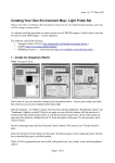
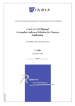
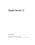
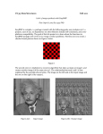
1
Dphlab Digital PHotographic LABoratory Michel Guitel december 2005 michel <dot> guitel <at> free <dot> fr Documentation Dphlab 1/43 december 2005 Table of contents Goal......................................................................................................................................................5 A bit of (little) history...........................................................................................................................5 Features.................................................................................................................................................5 Raw to image conversion.................................................................................................................5 Limitations.......................................................................................................................................6 Color curves.....................................................................................................................................6 Light adjustment and color balance.................................................................................................6 Automatic workflow........................................................................................................................6 Lens calibration................................................................................................................................7 Credits...................................................................................................................................................7 Licence..................................................................................................................................................7 Future....................................................................................................................................................7 Performances........................................................................................................................................8 Raw data conversion........................................................................................................................8 Thumbnail generation......................................................................................................................8 Initial thumbnail loading..................................................................................................................8 Several figures.................................................................................................................................9 My computer...............................................................................................................................9 Results.........................................................................................................................................9 Principles..............................................................................................................................................9 How to start dphlab..........................................................................................................................9 Workflows.......................................................................................................................................9 Example 1 : copy from the camera to the computer.................................................................10 Example 2 : image processing parameters (user task)..............................................................10 Example 3 : image processing..................................................................................................11 Input data.......................................................................................................................................11 Output data.....................................................................................................................................11 Lens calibration..............................................................................................................................11 Raw data processing......................................................................................................................12 User's manual......................................................................................................................................13 List of tabs.....................................................................................................................................13 Status zone.....................................................................................................................................14 Background job management : « Go » button..........................................................................14 General settings tab........................................................................................................................15 User's coordinates.....................................................................................................................15 Directory settings......................................................................................................................15 Raw data copy tab..........................................................................................................................16 Raw files tab..................................................................................................................................17 Dphlab 2/43 december 2005 Content......................................................................................................................................17 Sorting criteria..........................................................................................................................17 Selection....................................................................................................................................18 Image destination......................................................................................................................18 Lens...........................................................................................................................................18 Processing settings tab...................................................................................................................20 Zoom ratio.................................................................................................................................20 Computation in progress indicator............................................................................................21 Histogram..................................................................................................................................21 Color tab....................................................................................................................................21 Light tab....................................................................................................................................22 Contrast tab...............................................................................................................................22 Noise reduction tab...................................................................................................................22 Sharpening tab...........................................................................................................................23 General settings.........................................................................................................................23 Remark......................................................................................................................................24 Raw data processing tab................................................................................................................25 Lenses tab......................................................................................................................................26 Lens declaration dialog..................................................................................................................27 Vignetting dialog...........................................................................................................................28 Pattern image file selection.......................................................................................................28 Vignetting estimation................................................................................................................29 A little bit of theory...................................................................................................................30 Remark......................................................................................................................................30 Distorsion from a test pattern dialog.........................................................................................30 Pattern image file selection.......................................................................................................31 Distorsion estimation................................................................................................................31 Adjusting the threshold value for pattern detection.............................................................31 Pattern detection...................................................................................................................31 Checking and modifying the test pattern as found by dphlab..............................................31 Distorsion estimation............................................................................................................32 Remark.................................................................................................................................35 How to acquire the distorsion pattern image............................................................................35 Remark......................................................................................................................................36 Distorsion from a test image dialog..........................................................................................36 Pattern image file selection.......................................................................................................36 Distorsion estimation................................................................................................................36 A little bit of theory...................................................................................................................37 Associated files..............................................................................................................................38 Camera tab.....................................................................................................................................39 Installation..........................................................................................................................................41 Dphlab 3/43 december 2005 Prerequisites...................................................................................................................................41 Build...................................................................................................................................................41 Dependencies.................................................................................................................................41 Qt...............................................................................................................................................41 Gsl.............................................................................................................................................41 ImageMagick.............................................................................................................................41 Cimg..........................................................................................................................................41 Main build......................................................................................................................................41 Secondary build.............................................................................................................................42 Tool................................................................................................................................................42 Tricks.............................................................................................................................................42 Future developments..........................................................................................................................42 Features..........................................................................................................................................42 Translations....................................................................................................................................42 Dcraw.............................................................................................................................................43 Dphlab 4/43 december 2005 Goal The goal of dphlab is to help in digital raw photographic data processing. If you are the happy user of a digital camera, and if you prefer to use its raw data instead of processing them in the camera, dphlab is made for you. A bit of (little) history I started thinking of switching to digital photography during the year 2003. As I was already a single lens reflex camera user, I wanted a camera compatible with my lenses. I also decided not to be linked with the manufacturer's supplied processing software. This was not a quality concern, but a philosophic matter. Dcraw became my starting point but it did not cover the interactive process for image adjustments nor more advanced features like the lens defects correction. I started writing dphlab in 2004, having in mind a possible camera purchase by end 2004. Unfortunately, my classical (15 years old), faithfull camera heard of this and decided to go ill on the very first day of our summer family holidays. This had several consequences : we had to use disposable cameras during these holidays, I decided that we will never go again far away with one single camera, and we were ready to purchase a new, digital camera. The home computer was upgraded and prepared to receive bunches of big files, the budget was allocated and finally the camera joined the family. Since then, I processed all the data with dphlab, and I go on augmenting it to fullfill my needs. I will now try to improve it and make it usable for everybody. Features Raw to image conversion Dphlab turns raw data into image data. The raw files are decoded by Dave Coffin's algorithms, taken from his program called dcraw. The set of currently accepted suffices is .nef, .crw, .cr2, .mrw, orf, and raf for Nikon, Canon, Minolta and Olympus. Since the critical job is done in dcraw, I will add new suffices as soon as I am aware of them. Decoding is followed by the following steps : – data decoding, – Bayer matrix interpolation, – colour balance, light adjustment, – lens vignetting and distorsion correction, – contrast adjustment (general and local), – noise reduction, – sharpening. Dphlab 5/43 december 2005 Limitations Some camera data are currently not well read. The Canon 5D and Nikon D200 bodies currently fall in this category. The technical data are not always decoded. This happens for the CRW files from Canon, RAF from Fuji and MRW from KonicaMinolta. I could not check all the file types. Four situations are actually possible : – ignored file type due to an unknown suffix, – accepted file type, but technical data not read (this comes from metacam limitations), – accepted file type but image data badly decoded (Nikon D200, Canon 5D), – accepted file type, technical data well handled, image read (Nikon D70 and D100, Pentax *ist DS, Canon 1D and 20D at least). Color curves Dphlab can apply several types of output functions to decyphered raw data : gammalike or custom curves. The choice is made by the user, based on a preview window. Currently the curves cannot be edited but only displayed by a small, independant tool (vcurve). The curve files are read from a custom, XMLbased design or from ntc (Nikon) files. Light adjustment and color balance You can set light and color factors for any group of images, from one image taken as example. The color balance can be set by red and blue sliders or from a small grey area of the image (pipette tool). You may use the sliders to adjust the colour balance after pipette adjustment. Automatic workflow Dphlab automates the basic workflow of taking the initial files from the camera or the memory card, copying them to the computer disk drive and producing displayable images. The workflow is based on the files' date. When a raw data file is newer than the corresponding image file, or if no image can be associated with it, a task is initiated. The overall workflow includes several steps : – raw data copy onto the hard disk of the computer, – thumbnail generation, – interactive processing parameters adjustment, – distorsion and vignetting correction, based upon previous lens calibration, – full resolution image creation. Dphlab 6/43 december 2005 Lens calibration The lens vignetting and distorsion can be calibrated. The resulting measures are kept in configuration files, and later used to correct the images. The calibration data can be exported to help exchanges between users, and build a lens database. Credits This program could not have been made without Dave Coffin's dcraw that provides raw data decoding algorithms. I warmly thank him for this unique source of inspiration : http://www.cybercom.net/~dcoffin/dcraw/. The meta data are read thanks to metacam http://www.cheeseplant.org/~daniel/pages/metacam.html. The interpolations used in the vignetting and distorsion evaluation come from gsl (the GNU Scientific Library). The curve interpolation are also based upon the GSL spline functions. NTC file curves are read thanks to Shawn Freeman (NikonCurveGenerator from http://pages.quicksilver.net.nz/pepe/d70/Linux_and_Nikon_D70.html . I also used Cimg image processing library from David Tscumperlé (GREYC UMR CNRS 6072, Image group, http://cimg.sourceforge.net/ ). I also found inspiration in ufraw which is one of my references in the raw digital photographic data processing. Licence I put this software under the GPL (GNU Programming Licence). Future I will try to make dphlab suit my needs around digital photography. I already identified the following areas for improvement : – – – QT help system integration, metadata reading from other maker than Nikon (Pentax and Canon files are currently only partially decoded and the other ones are not at all), image indexing (I will try to generate common index files, that can be read by free indexing software), – predefined color balance settings, – color curves modification, – tool to help in defining noise reduction and sharpening settings, – noise and accentuation management : predefined profiles associated with camera model and ISO picture setting, Dphlab 7/43 december 2005 – external postprocessing filters, – performance optimization, – text metadata burning in the image, – new camera types (Sigma cameras are currently not working), – customizable file renaming schemes that would operate from metadata, – dphlab launching from the GUI and not only from a shell window. I will also try to address your suggestions and/or provide you the starting point to further develop this software. Performances Digital image processing costs a lot in terms of CPU ressources. The most important figures are described hereafter. They are only examples and your findings are likely to be different on your computer. Raw data conversion This computation is made by the external executable mgraw in background. It is CPU intensive. Its first step is written by Dave Coffin in his program dcraw. I try to change his code to the least possible extent. The second step (optional) is lens defect correction (vignetting and distorsion). I believe that it could be improved but my first priority is to validate its principles with real images. Obviously, those who own a fast CPU and even more, a multiprocessor or dualcore one, will be happy with dphlab. I personnaly do not use this kind of processor so I cannot write anything actual about it. On the other hand, those who run a notsofast computer will prefer to stop the background processes while they adjust the processing settings. The user interface will be more responsive and pleasant to use. You start or stop the background processes with the « Go » button at the bottom, left corner of the main dphlab window. You may also run mgraw in a terminal window and make it read the processing parameters previously written by dphlab. This makes it possible to compute bunches of images in batch mode. Thumbnail generation This is done once in background mode when loading the raw data files from the digital camera, the memory card or an external disk. If your computer is not fast enough, just leave it alone when it produces the thumbnails. Initial thumbnail loading This is done at every start of dphlab, from the thumbnails computed in the former step. This Dphlab 8/43 december 2005 produces inmemory icons that are used in the raw data file table. This phase can be lengthy if many images are present (from 30 seconds to 1 minute on my computer for almost 2000 files). Several figures My computer AMD XP 2000+ (equivalent to a 2Ghz Pentium according to AMD). 512 Mo RAM. Hard disk : Maxtor UDMA 133, 160 Go, 7200 rpm, 8 Mo cache memory. Results Remark : these measures where taken from an executable made with g option (debugging option on) of g++. Raw data conversion from a Nikon D70 file (6,1 Mpixels) : Without vignetting nor distorsion correction : 22 seconds. With vignetting and distorsion correction : 28 seconds. With contrast adjustment (general and local) : 32 seconds. With noise reduction for the blue component only : 52 seconds. With noise reduction for the blue component and luminance : 64 seconds. Noise reduction for the red, green, blue components, luminance and chroma : 1 minute, 54 seconds. With sharpening (radius 5, coef 0.4) : 2 minutes, 43 seconds. Thumbnail generation : 3,5 seconds/thumbnail. Icon reading from the thumbnails : 46 seconds (among which 32 seconds are pure CPU) for 1639 images. Principles How to start dphlab Dphlab can currently only be launched from the command line terminal : $ dphlab & Workflows The workflow principles are similar to the ones of Unix make utility. Each workflow has an input directory and an output directory. They are recursively watched to Dphlab 9/43 december 2005 build the list of files that match pattern matching rules. The rules define a radix that identifies the file, starting from the file name. When a file under the input directory and an other file in the output directory share the same radix, the first one is supposed to produce the second one. If the latter is older than the former, it must be regenerated. If the resulting file does not exist, the same rule applies. Example 1 : copy from the camera to the computer Input directory : /mnt/camera Input pattern : *.nef, *.crw, *.cr2, *.mrw, *.orf, *.raf Sources Raw data files Thumbnails Processing parameters (user defined and automatic) Processed images Output directory : /home/michel/prod_dphlab/raw Output pattern : *.nef, *.crw, *.cr2, *.mrw, *.orf, *.raf The file dsc_0763.nef is found in the directory dcim/NCD70 under /mnt/camera, dated feb 13rd, 2005, after the digital camera is connected to the USB port of the computer. No dsc_0763.nef file is found under /home/michel/prod_dphlab/raw . A task is initiated in order to generate the resulting file. The (dphlab internal) rule simply copies the input file to the output dir. After this task is executed, /home/michel/prod_dphlab/raw/dsc_0763.nef exists and holds a copy of the camera's dsc0763.nef file. Its timestamp is the copy one. Example 2 : image processing parameters (user task) After dsc_0763.nef is copied to /home/michel/prod_dphlab/raw directory, no dsc_0763.dph file is Dphlab 10/43 december 2005 found under « /home/michel/prod_dphlab/processing parameters » directory. The corresponding task is queued in the « processing parameters » list of pending tasks. The user finds it in the list of settings to be done. It selects it and enters the « processing parameters » tab of dphlab. Dphlab displays a preview of the image and enables the user to set the color balance, brightness and output settings. He or she validates the settings by pressing « OK ». dsc_0763.dph file is created in « /home/michel/prod_dphlab/processing parameters » directory, containing the processing parameters choice. dph_0763.dph contains also the path to the raw data file i.e. « /home/michel/prod_dphlab/raw/dsc_0763.nef » . A group of files sharing the same processing parameters will point to the file that was taken as reference. Example 3 : image processing The file dsc_0763.dph now exists in the « /home/michel/prod_dphlab/processing parameters » directory but no dsc_0763.png file can be found under the « /home/michel/prod_dphlab/processed images » directory. Dphlab queues a task using dsc_0763.dph file, that will eventually launch mgraw with the corresponding arguments. This program produces « /home/michel/prod_dphlab/processed images/dsc_0763.png ». The photographic process has reached its current end. Input data The raw data file are processed by dcraw input procedures. Their metadata are decoded by metacam algorithms. Any file that can be processed by both can be fully used by dphlab. Dcraw capabilities being used for raw data conversion allow almost any digital raw data file to be processed by end 2005. Making dphlab compatible with new cameras only needs to integrate new dcraw decoding algorithms and possibly add the suffix of its raw data files to the list of accepted suffices. Output data Dphlab mainly produces png files in 8 or 16 bits per color sample formats. We already saw that it also produces 8 bits JPEG thumbnails. Lens calibration The lens distorsion and vignetting can be measured after pattern images. The vignetting effect depends on the actual aperture, and the focal distance for a zoom lens. The distorsion depends on the focal distance and on the distance from the camera to the objects. My own camera does not record this distance so an automatic distorsion correction is theorically impossible. I choose to activate it « by hand » for each image being processed. Two calibration methods are implemented in dphlab. The first one relies on a special pattern made of crosses. The second one only needs a real scenery with a straight, almost horizontal line. The resulting measurements are kept in a database Dphlab 11/43 december 2005 file. These data can be exported or imported in order to be shared between dphlab users. Raw data processing The raw data processing produces displayable images. It is made of the followings steps : – camera source characterization, – sensor data decompressing, – sensor data interpolation to produce a redgreenblue matrix, – image rotation (portrait or landscape), – color balance after user input, – distorsion and vignetting correction after the lens and picture data (optionnal), – curve function (fixed gamma or custom), – contrast adjustment, – noise reduction, – sharpening, – PNG file generation. Dphlab 12/43 december 2005 User's manual List of tabs The main window of dphlab consists of a set of tabs and a status zone. Each of the tabs shows some aspect of the photograph's tasks. The status zone displays the current situation of the job queues. The tabs are : – settings, – raw data copy, – raw files, – processing settings, – raw data processing, – lenses, – cameras. Dphlab 13/43 december 2005 Status zone This area displays the numbers of tasks to be done and the total number of tasks for each workflow. Background job management : « Go » button The « Go » button starts or stops the background jobs. When dphlab is required to stop them, they are gracefully stopped after a task has been performed. My advice is to start background processing for raw data loding from any source but to stop when you set the processing settings if your computer is not responsive enough. You just have to restart background processing when you are done with the image you want to process, and go for lunch or even bed if many files are to be processed. Dphlab 14/43 december 2005 General settings tab This tab gives access to the user's coordinates and the directory settings. User's coordinates These data will be used when the user changes or adds some lens or camera profile. Directory settings This defines the directory where dphlab will look for new or missing files. You may type in the directory paths, or use a push button to interactively browse the directory tree on your computer. Three directories at most can be set as raw data sources. This enables you to simultaneously look for new files in a camera, an external hard drive and a card reader. Dphlab 15/43 december 2005 Raw data copy tab This tab shows a detailed view of the copy process : the files yet to be copied from the input directory to the raw data directory bear a RED point while the already copied files bear a GREEN point. Dphlab 16/43 december 2005 Raw files tab This tab displays a list of the raw data files that are ready to be processed with the user's help. Its goal is to provide an easy way to select data files that will be processed with the same parameters. The set of selected files will share the settings defined in the « processing settings » tab upon the unique, primary selection. Content The meta data of each file are displayed in a row with an icon of the image. One more time, a file to be processed is signaled by a RED point and an already processed file is marked by a GREEN point. The date and time of the picture are displayed in the table. When you scroll horizontally the table, you can notice that the technical data of the image are available, like actual lens aperture and focal distance, min and max lens aperture and focal distance, camera make and model as well as flash light usage and ISO setting. Even more, the lens model can be guessed by dphlab, or set by you in a scroll down list. Sorting criteria You can sort the list according to any field, by ascending or descending order. This is done by clicking in the column headers. Dphlab 17/43 december 2005 Usually, you will sort by date in order to group images that were taken almost at the same time thus in similar light conditions. Selection For instance, 15 pictures were taken with the same light. You just need to select all these similar photos, choose the most relevant one and switch to the « processing settings » tab. Multiple selection of a range of lines is done by left clicking on the first line to select, then Shiftleft clicking in the last line to select. If you want to select files one at a time, just use Ctrlclick. You cannot individually deselect files. The selected lines are highlighted. The primary selection is the lastly selected one. It is marked by a YELLOW point in the leftmost column. You can see here that you may select already processed files to reprocess them. Image destination Most of the raw data files will produce photographs. However some of them will be used to calibrate your lenses and help you to produce better images. These special files can be flagged as «vignetting» or « distorsion » by using the dropdown menu in each row. It is set to « image » by default. Lens The lens used to make the image is usually guessed after the technical data of the raw data file like min and max focal distance and aperture recorded by the camera in the Exif tags. Dphlab 18/43 december 2005 When an image was taken with a not yet known lens, its lens label will be « new... ». You can go and select this choice to better define this lens. The lens declaration window will then open, enabling you to assign it a label. You can also calibrate it from this window. Even if this is quite unlikely, it might also happen that several lenses match the focal range and aperture. This happens when a converter is associated with a base lens (x1.4, x2). In this case, you can select the actual lens with the same drop down menu after having declared the combination as a new lens. Before you calibrate the lens, do not worry about this, keeping the lens unknown is harmless : the image will just be computed with no distorsion and vignetting correction, as with any usual raw converter softwares. You will reprocess it later when you have calibration data for your new lens. Dphlab 19/43 december 2005 Processing settings tab This tab enables processing parameters to be set, by showing their result in a preview window. This tab shows the current settings result on the right. The left image shows the initial settings result. The histogram of the current result is shown in the right, middle area. The file name and the technical meta data of the displayed image are shown. The various processing parameters are set in several tabs. These tabs are presented in the processing order. Zoom ratio The zoom ratio of the preview image can be adjusted between 1:10 and 1:1 (full resolution). The magnified area is moved by left clicking in the leftmost image. The full resolution image is allowed after the full size image has been loaded. This computation is done in background mode so that you can adjust the first processing parameters on the reduced size image. The full resolution image availability is shown by the red/green indicator to the left of the zoom slider. Noise reduction and sharpening settings are enabled when the preview image is shown at full Dphlab 20/43 december 2005 resolution. The lights in the corresponding tabs are then set to green. Computation in progress indicator The « work in progress » indicator is animated when any processing parameter is changed and the resulting image is not yet available. You may always adjust the settings : the computation will be interrupted and restarted with the new values. Histogram Warning : the histogram only shows the color statistics of the displayed part of the preview image. Color tab The images are automatically rotated if the corresponding Exif tags were set by the camera. However, you can change this default rotation with the left or right rotate, flip buttons. You can adjust the color settings (red and blue coefficients, compared to the green component). If you prefer to use a pipette to pick a grey area in the image, press the pipette push button, then move the cursor above the righ image. The surrounding area is shown at the histogram place. A small area is sampled around the cursor when you leftclick. Red and blue coefficients are computed from the average colors of this area which is then supposed to be grey. The corrections are immediatly applied to the preview image. You are free to repeat this operation as long as you are not happy with the result. Dphlab 21/43 december 2005 Light tab You can adjust the brightness and select the color curve type among predefined ones or gammalike function and choose the output type. You can also ask the luminance histogram to be equalized. Contrast tab This tab adjusts the general contrast of the image and its local contrast. The local contrast operates on the difference between any pixel and the average value of its surroundings. Boosting it increases the microcontrast. The radius setting defines the size of the surrounding area where the average color value is computed. Contrast values equal to 1 do not change the image. Noise reduction tab This tab is enabled when the preview ratio is 1. A green light is then lit in its title. You can set noise reduction independantly for each component of the image : red, green, blue, as well as luminance and chroma. Blue noise is usually higher at high ISO sensitivity. Dphlab 22/43 december 2005 Sharpening tab This tab behaves like the « noise reduction » one : it is active only when a value of 1 is uses as preview ratio. Sharpening increases luminance difference between any pixel and its surrounding area. The reference is the median value of the luminance around the pixel, computed in a square whose side is given by the median radius value. A sharpening coefficient of 0 does not change the image. Remark : you are advised to set a noise reduction before sharpening if you want not to boost the noise in the image. Obviously, you will have to decide this, after the ISO settings of the image. General settings You can ask for highlighting the « burnt » pixel. All the pixel where one color component has been clipped to the maximum value will be red colored in the preview window. You can select the output type (8 bits/color, 16 bits/color). The 8bit output produces final images for printing, where 16bit output is intended for high quality postprocessing with tools that manage such data like cinepaint (http://cinepaint.movieeditor.com/ ). The distorsion and vignetting corrections can be enabled or disabled. When enabled, dphlab uses the lens calibration and the image technical meta data to compute the defect magnitudes and produce better images. You can also decide to do NOTHING with the raw data files if they do not deserve any more processing. You just have to check the « Ignore the image » check box. An almost empty image will be made to replace the one you decided to ignore. When the settings produce the image you wish, just press « OK » and they will be saved for all the initially selected images. The processing commands are queued for future execution. Dphlab 23/43 december 2005 Remark If you selected several raw data files, they will share the processing parameters you define but they will NOT share the automatic ones, i.e. The color balance, processing type will be the same for all of them. The vignetting and distorsion corrections will be computed independently for each of them depending on their actual optical conditions (lens, focal distance, aperture). Dphlab 24/43 december 2005 Raw data processing tab This tab shows the status of the queued jobs whose task is to process raw data files and produce images. The jobs that are already finished bear a GREEN point in the leftmost column. Those not yet done are marked by a RED point. Dphlab 25/43 december 2005 Lenses tab This tab displays two lists of lenses. The left one shows YOUR lenses. The right one shows the set of known lenses. You can copy selected lenses between the lists by using the left and right double arrows. You will later read how to calibrate your lenses. When this process is done for one lens, you can export its data to a description file and/or copy its description to the set of known lenses. The intent is to provide an easy way to share lens descriptions between dphlab users. You can also remove lens descriptions from your set of lenses by using the « remove » button. You can edit the lens description by selecting it in the left list, and press the « edit » button. The following dialog will display. Dphlab 26/43 december 2005 Lens declaration dialog The lens description is composed of : – a fixed string made after the technical data of the lens. This string is displayed as the form title above the entry fields. This string is also used in « lens designation » column of the raw file list to identify the lens that took the photograph, – a label string, – the manufacturer of the lens, – the mount of the lens, – – a free text that describes the lens. It could be « good old 180 mm, f2.8, manual focus » if you want, a flag that indicates whether the lens is a zoom one or not. If not, the second focal and aperture zones will not display, – one or two field(s) that contain(s) the focal range, – one or two field(s) that contain(s) the maximum aperture at the corresponding focal distance, – technical data that define the distorsion and vignetting values at several imaging conditions (focal distance, aperture value for the vignetting). The push buttons at the bottom of the dialog enables you to calibrate the distorsion and vignetting values. They activates several dialogs. « Reevaluate all » uses all the files aimed at « vignetting » or « distorsion » in the raw data tab to perform optical defects measurement. « Evaluate new » uses the new files aimed at « vignetting » or « distorsion » in the raw data tab to perform optical defects measurement. « Vignet... » activates a file selection dialog then a vignetting calibration dialog. The file selection enables you to choose a raw or final pattern image file. This image must be a photograph of a Dphlab 27/43 december 2005 uniform area. The resulting photograph should show uniform value but the vignetting effect makes the corners darker. The precise measurement of this effect allows its correction when real photos are made at the same lens focal distance and aperture values. Distorsion buttons. There are two ways to evaluate the distorsion of a lens. The first one uses a special pattern made of evenly spaced crosses. This pattern should be phtographed from quite a small distance for it to fill the field of view. The drawback is, that the distorsion value can be useless for long range pictures. The second one use a real scenery that includes a straight, horizontal line. For instance, it can be a picture of a palace whose basement is when visible. We must then adjust a line on the screen to make it overwrite the scenery line. The magnitude of the line curvature gives the lens distorsion. These methods being equally usefull depending of your habits, they are both implemented in dphlab. « Distorsion with pattern» activates a file selection dialog, then a distorsion calibration dialog. The file selection enables you to choose a raw or final pattern image file. This image must be a photograph of a the distorsion pattern provided with dphlab. The resulting photograph should show a rectangular grid of points but the distorsion effect slightly into a cushion or a barrel. The precise measurement of this effect allows its correction when real photos are made at the same lens focal distance value. « Distorsion with image » activates a file selection dialog, then a distorsion calibration dialog. The file selection enables you to choose a raw or final pattern image file. This image must be a photograph of a real scenery with a straight, almost horizontal line close to one edge of the image. This line should at least cross most of the image if not all of it. The precise measurement of this effect allows its correction when real photos are made at the same lens focal distance value. « OK » closes the dialog AND saves the changes : the lens definition is updated after the changes made during the session. « Cancel » closes the dialog without saving the changes : the lens definition is NOT updated. Vignetting dialog Pattern image file selection Dphlab 28/43 december 2005 This file selection dialog enables you to select a pattern image file that will be used for the vignetting measurement. You may select a raw data file or an image file. Vignetting estimation This dialog displays the patterm image and several controls to help in measuring the vignetting effect. The path of the pattern file in use is shown in the title of the dialog. Two curves are put as overlay on the pattern image. The blue curve shows the initial average density as a function of the radius from the image center. The green one shows the current density correction. It is optimal when the green curves is flat. The red grid helps you to evaluate the vignetting as a function of the radius from the image center. The side radii are displayed by vertical lines. The « evaluate » push button performs an automatic evaluation of the vignetting effect, and produces a curves that best fits with the initial one. Dphlab 29/43 december 2005 You may manually adjust the vignetting estimation by using the top right slider. You can also display a circle in the image and the corresponding line on the graph, by left clicking in the image : the circle will change according to the cursor moves in the image. If you selected an image file in the first step, the aperture and focal distance of the lens being used are unknown. You must type them in the corresponding entry fileds at the bottom of the dialog. If you selected a raw data file, they are displayed but you cannot change their values. A little bit of theory The light intensity at any point of the image plane depends on its position relative to the field center. A simplified form of the relation is given by the formula : I(r) = I(Center) * cos4(theta) where r is the radius from the image center and theta is an angle that depends only on r and the geometry of the lens. (schema taken from « Calibration radiométrique de caméra, JeanPhilippe Tarel, INRIA 1995). Given this relation, estimating the vignetting effect needs to evaluate one parameter similar to a distance. Dphlab does this automatically from a pattern image, assuming it is uniformy illuminated. Remark The actual vignetting effect is different from this simplified model. This explains why the correction is not always perfect even if it is better than nothing. I would receive a more accurate model with pleasure, and I would try to implement it in the future. Distorsion from a test pattern dialog Distorsion measurement is performed by using a dedicated test pattern. It is available as a pdf or Dphlab 30/43 december 2005 OpenOffice file. See below how to use it and produce the needed calibration files. Pattern image file selection This file selection dialog enables you to select a pattern image file that will be used for the distorsion measurement. You may select a raw data file or an image file. Distorsion estimation This dialog displays the patterm image and several controls to help in measuring the distorsion effect. The path of the pattern file in use is shown in the title of the dialog. The measurement process is made of several steps : – adjusting the threshold value for pattern detection, – pattern detection, – checking and modifying the test pattern as found by dphlab, – distorsion estimation. Adjusting the threshold value for pattern detection You can use the « automatic threshold » button first, and adjust the threshold value later. This value is used by dphlab to detect black points in the image, opposed to white ones. Adjust the threshold value with the left side slider. Some grey, « moire » patterns are often displayed in the image but are only artefacts. They do not prevent normal pattern detection. Pattern detection Dphlab can perform an automatic detection of the pattern points. It displays the result as a colored overlay. The points are linked by lines and numbered from top, left corner to bottom, right corner. Checking and modifying the test pattern as found by dphlab Usually you have to help it in this process. You can add points with the « add point » button. Dphlab will then use your input and look for black pattern around the point you designate by left clicking in the image. Adjust the threshold value to better highlight the wanted patterns. When Dphlab 31/43 december 2005 several points share the same location, you can delete one of them with the « delete point » button followed by leftclicking close to its location in the image. One single point is removed at once. The pattern is well defined when the points shape a grid in the image. Distorsion estimation Press the « evaluate distorsion » button to get an automatic measurement of the distorsion value. The image and the grid are then adjusted following the distorsion estimation. If the result is fine, just validate by pressing « OK ». If not, you can adjust the distorsion estimation with the top, right slider. Dphlab 32/43 december 2005 Dphlab 33/43 december 2005 Dphlab 34/43 december 2005 Remark If you selected an image file in the first step, the focal distance of the lens being used is unknown. You must type it in the corresponding entry filed at the bottom of the dialog. If you selected a raw data file, it is displayed but you cannot change its value. How to acquire the distorsion pattern image The camera must be installed on a tripod in order to prevent motion blur. You should also select an aperture so that the image quality be optimal (close the diaphragm at least two stops from the maximum aperture of the lens). The shutter speeds between 1/15 and ½ second should not be used since the mirror generates vibrations. If you were to use such shutter speed, you can either use a smaller aperture (higher aperture number) or change the ISO setting of the camera. The test pattern must be put on a flat area, right on the camera axis. The grid pattern needs not to be horizontal : dphlab is not sensitive to the pattern orientation. Install the camera and the test pattern so that its image almost fills the viewing field of the lens according to the focal distance in use. Dphlab 35/43 december 2005 You should use a remote cable release in order to prevent camera motion when triggering the shutter. If you do not have any, you can safely use the self timer of the camera. Remark The suggested method is obviously convenient since it takes place in house. However it has some drawbacks from the short distance of the pattern object, compared to real objects like monuments. Distorsion from a test image dialog Pattern image file selection This file selection dialog enables you to select a real image file that will be used for the distorsion measurement. You may select a raw data file or an image file. Distorsion estimation This dialog displays the patterm image in greyscale and several controls to help in measuring the distorsion effect. The path of the pattern file in use is shown in the title of the dialog. The measurement is made by adjusting three points so that a curved line going through them overwrites a straight line in the real scenery. The distorsion value is automatically, continuously computed by dphlab while the control points are moved. A coloured grid is also displayed to help in adjusting the points. Operation sequence : Put three points on a straight line in the image. Creation of the points is performed by left clicking in the image. Moving a point is achived by left clicking right to it, then dragging it in the image. The distorsion is recomputed. The coloured grid is stretched accordingly. This first example shows an intentionnaly too high distorsion : Dphlab 36/43 december 2005 This second example looks better : A little bit of theory The distorsion transforms a rectangle into a cushion or a barrellike shape. f is the distance between the rectangle side and its image, taken at the midpoint of the width. k is the distorsion measure, usually noted as a percentage. Dphlab 37/43 december 2005 k = f / w * 100 Its value is usually between 2 % and +2 %. The underlying model of the distorsion follows. The distorsion effect moves any point of the image along the line going from the image center to the point. The radius (r) becomes distor(r) with the folllowing formula : distor(r) = r (1 + a1.r + a2.r2 + a3.r3) r2 is the square of r r3 is the cube of r A simpler mathematical model takes into consideration only the highest rank term of the series. This model is the only one currently implemented in dphlab. Things could change in the future. Associated files my_lenses.xml This file describes the user's lenses. all_lenses.xml This file describes the set of known lenses. my_cameras.xml This file describes the user's cameras. all_cameras.xml This file describes the set of known cameras. <curve>.ccc These files describe colour correction curves. <radix>.dph These files contain the processing parameters for converting <radix>.nef (or .crw) into an image file named <radix>.png . Dphlab 38/43 december 2005 Camera tab This tab displays two lists of cameras. The left one shows YOUR cameras. The right one shows the set of known cameras. You can copy selected cameras between the lists by using the left and right double arrows. You will later read how to describe your cameras. When this process is done for one camera, you can export its data to a description file and/or copy its description to the set of known cameras. The intent is to provide an easy way to share camera descriptions between dphlab users. You can also remove camera descriptions from your set of cameras by using the « remove » button. You can edit the camera description by selecting it in the left list, and press the « edit » button. The following dialog will display. Dphlab 39/43 december 2005 Dphlab 40/43 december 2005 Installation Prerequisites Qt, convert, ppmmake, ppmlabel (ImageMagick), mgraw (build from source files in dphlab source directory). Build Dependencies Qt dphlab heavily relies on the Qt library. Gsl dphlab uses gsl (GNU Scientific Library) for the interpolations. There are such functions in the distorsion and vignetting estimation, based upon calibration data at discrete values of the parameters (aperture, focal distance). The color correction curves are also computed with gsl help. ImageMagick convert, ppmmake and ppmlabel are used from ImageMagick through system() calls. Dphlab first checks their availability and reports any missing program when started. Cimg Dphlab uses internally the Cimg image processing library. This one is written as an include file that defines many templatebased methods. It is included in the source package of dphlab. Thus there is no external binary library to look for. Main build $ cd dphlab ; make This builds the dphlab executable file. You must move it somewhere in the executable path (/usr/local/bin or ~/bin for instance). The international message files (dphlab_fr.qm is currently the only one) should be put in « /usr/local/share/dphlab » directory. Dphlab 41/43 december 2005 Secondary build $ make f Makefile.mgraw After the main build is successfully done, this produces the executable file mgraw, that performs actual conversion from raw data to ppm image data. mgraw must be put somewhere in the executable path (/usr/local/bin or ~/bin for instance). Tool The tool program vcurve has been made, in order to display a color correction curve. It loads a .ccc file and plots it in its main window. It does not edit the curve. Just cd to the vcurve directory and build the executable file vcurve : $ make You should then move vcurve somewhere in your executable search path, for instance in / usr/local/bin or ~/bin. Tricks A special klocale.h file has been created in dphlab to allow the successful compilation with localization (tr() macro in .ui files). Future developments Features Help to better visualize the processing effects (contrast adjustment, noise reduction and sharpening). External, userdefined filters. Interactive userdefined color curves. Key word based indexes. Translations The translations have been done with qtlinguist tools. The process is well documented in the QT3 books. The translation process follows : $ cd dphlab/dphlab $ lupdate dphlab.pro $ qtlinguist & then open the dphlab_fr.ts file (for the french translation) Dphlab 42/43 december 2005 edit its content and save it $ lrelease dphlab.pro This produces a new dphlab_fr.qm file, to be put in your /usr/local/share/dphlab directory where dphlab will look for it. Dcraw The evolutions of dcraw should be integrated. Dphlab 43/43 december 2005