1
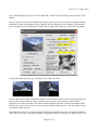
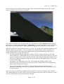
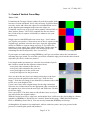
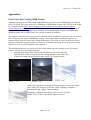
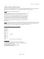
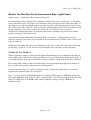
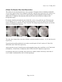
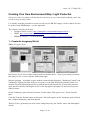
Issue 1.0, 17th May 2013
Creating Your Own Environment Map / Light Probe Set
(Please note that everything in this document is based on my very limited understanding, and I may
well be wrong on many points)
I’ve already used this procedure to create several sets of LDR JPG images. I believe that it can also
be used to create HDR images – see the Appendix.
The software you'll need (all free):
• Terragen Classic v0.9.43 ( http://planetside.co.uk/products/terragen-classic )
• GIMP ( http://www.gimp.org/downloads/ )
• HDRShop Version 1 - ( Link from here http://www.hdrlabs.com/tools/links.html )
1 - Create An Imaginary World
Tools: Terragen Classic
Don't worry if you can't read the writing on the screenshots above – they're just to help you check
that what you see on your computer looks about right.
Start the program – by default it opens with two panes already displayed, “Rendering Control” and
''Landscape', slightly overlaid. If they're not open you can click the buttons with the picture of a
monitor (top left) and the button below it with the green hill respectively. (If any other panes are
open just close them by clicking the red 'X' at the top right of each pane. It's not necessary, but it
reduces clutter.
On the 'Landscape' pane click the 'Generate Terrain' button. This opens a new 'Terrain Genesis'
pane.
Click the 'Generate Terrain' button on this pane. The black square on the 'Landscape' pane will turn
into a random black,grey, and white pattern.
That's it! You've generated your new world, with ground, sky, sun, clouds, water, and atmospheric
effects!
Page 1 of 10
Issue 1.0, 17th May 2013
Now you'll probably want to see what it looks like. On the 'Terrain Genesis' pane click the 'Close'
button.
In the 'Camera' section of the 'Rendering Control' pane set a few of the camera parameters (those
marked in yellow on the image below), and the click the 'Render Preview' button. With luck the
grey rectangle top left will become a blocky but recogniseable landscape, like in this screenshot:
On the other hand you may get a weird preview render like these:
If your render preview has large black patches at the bottom or bits of terrain stopping in mid-air
just go back to the 'Landscape' pane, generate a new terrain, check that the yellow camera
parameters are still correct the same (most of them should be but the 'Camera Orientation' pitch,
bottom row, may need to be reset to zero), and do another render preview . Do this until you get a
reasonable render preview.
Now click the ‘3D preview’ button on the main Terragen window (far left, second from bottom,
with '3D' written on it. A progress indicator is diplayed while it sets things up, and then a new '3D
Page 2 of 10
Issue 1.0, 17th May 2013
Preview window opens. Simply click anywhere in the window and drag the mouse left or right –
you're rotating the camera in your 3D world!
You want to check that you can rotate a full 360° in azimuth (left-right) without getting anything
that seems as if you're looking through or underneath the terrain. Looks like I've got a problem in
this 3D preview! Simple answer – you've guessed already, go back and generate a new terrain!
With luck you'll get a terrain that works after a few tries. If not then you're probably thinking “there
must be another way to do this?”. You've probably also noticed that the camera is usually on a
steeply sloping hillside, and you get the problem when you look towards the up-slope. Here's a
couple of hints before you get too frustrated:
– Try increasing the 'Fixed Height Above Surface' for the 'Camera' from 2m to 10m, 50m,
100m, 500m even – that'll usually fix it! I chose 2m purely because that's about eye-level for
a person standing on the terrain, and that's usually a good camera height. But remember that
we're just creating a background image for an environment map/light probe set, so feel free
to increase the height.
– Alternatively try editing the terrain. The 'View/Sculpt' and 'Modify' buttons on the
'Landscape' pane are a good place to start.Or use the 'Generate features on existing terrain'
button of the 'Terrain Genesis' pane.
– Or you could just move the camera to a piece of flatter terrain! (the yellow camera
parameters will change, but by now you should understand which ones don’treally need to
be set as I stated...)
Once you've got a terrain that you think looks okay SAVE IT! On the 'Landscape' pane click the
'Save' button and give it a name. It'll be saved as a Terragen Terrain file with a .ter extension. As far
as I know this file type can only be opened in Terragen.
Page 3 of 10
Issue 1.0, 17th May 2013
N.B. You've only saved the terrain here, not the rest of the environment. If you want to save the rest
of the environment do this from the main Terragen window’s menu bar – World File > Save World.
2 – Create Six Separate Cube Map Renders
Tools: Terragen Classic
We continue within Terragen Classic...
On the 'Rendering Control' pane click the 'Camera Settings' button – a new 'Camera Settings' pane
will open. Change the 'Zoom/Magnification'setting from 1.414 to 1 and then 'Close' the pane. This
has set the camera to a 90° field of view which we need to create the renders for our cubemap.
On the 'Rendering Control' pane set all three 'Camera Orientation' parameters (head, pitch, bank) to
zero again and do a Render Preview. Do the same with hedings of 90°, 180° , and 270° . If they all
look okay then you're ready for the next step. If any of them don't look right – I think you know
already!
I think you're getting familiar with the Terragen interface by now, so I won't give as much detail for
the rest of the instructions. Next step is to create our six renders for the cube-map. On the
'Rendering Control' set the Detail slider to maximum, Image Size to 960x960 (or any size you want,
but it must be square – for your first try make it rather smaller, say 400x400), ensure both 'Land and
'Sky' are checked, and then hit 'Render Image'. It'll take a while, and gradually appear bit by bit, but
eventually a little box will pop-up telling you it's complete. The terrain will probably look like rock,
and hopefully you'll be surprised at just how realistic it looks.
SAVE THE RENDER TO DISK!
It'll be saved as a BMP. Give it a meaningfull name, I use a scene name plus n, e, s, w, u, d for
north, east, south, west, up and down, e.g. (Scene1-n)
Do the same with ‘head set to 90 (east) and 270 (west). But for head=180 (south) also set bank=180
– this will make the image upside down, which is what we need for the vertical cross cube-map
we're making.
We also need a straight up and straight down render. Set head=0 and bank=0 and then do the up
render with pitch=90, and the down render with pitch= -90.
Don’t forget to save each render.
Page 4 of 10
Issue 1.0, 17th May 2013
3 - Create A Vertical Cross Map
Tools: GIMP
I found that the Terragen Classic renders fit perfectly together, both
in terms of colour and detail. So it's only necessary to position them
correctly, and to add a bit to the edges to avoid white/black curves
on the angular/equirectangular maps where the edges are.
I found the easiest way to do it was with a primary colours PNG (or
other lossless format – NOT JPG!) template like the one shown
here. Each of the six squares is 960x960 (or whatever size your
renders are).
Simply open it with GIMP and create a new layer – this is where
you’ll paste your renders. Colour-select one of the six squares on the
original layer, and then select the new layer. Open the appropriate
render in GIMP as a separate image and copy it. Go back to the
template, on your empty layer, and do 'Paste Into'. Do the same for
each render in the appropriate square. You should end up with
. Vertical Cross Template
something like the second picture. Save it as an XCF.
If you export as-is and convert using HDRShop you'll get curved lines where the unconnected
cubemap edges get joined. To avoid this you need to extend the edge pixels into the thin coloured
strips that you can see in the two pictures.
I use simple masks (not shown) to select the row/column of pixels
that I wish to extend into the adjacent coloured areas:
- a one-pixel wide column for the red area
- a one pixel wide column for the cyan area
- a one-pixel high row for the yellow area.
- a one pixel high row for the green area
Once you have the one-pixel row/column selected go to the layer
where you have the pasted renders and 'Copy', 'Paste As New
Image'. Scale the new image in one dimension (columns scale width
to 500, rows scale height to 500.
Create a new layer in the original image for the edge extensions.
Select the two coloured areas for the appropriate edge extension on
the template layer, then select the new layer and 'Paste into'. Do this
for all four edges.
Save it as an XCF. You don't want to redo all that! Once saved you . All six renders pasted in
can safely delete the original renders...
With the vertical cross layer, edge layer, and template layer visible save the whole thing in a format
suitable for HDRShop. I decided to use a lossless format at this stage – BMP (R8,G8,B8 and no
RLE, or HDRShop won’t like it). You can use any format that HDRShop will accept.
(Although this all sounds a bit complicated , tedious, and error-prone, once you get used to the
process it's actually quite quick and painless!)
Page 5 of 10
Issue 1.0, 17th May 2013
4 - Convert The Cube Map To Equirectangular And Angular Formats
Tools: HDRShop
This is very easy. Open HDRShop.
Open the vertical cross image file you exported from GIMP (drag and drop onto the HDRShop
window).
Select the gamma curve you want (I use the default, 2.2, for computer monitors. Not sure if I'm
correct).
Check your image is actually there, use ‘Ctrl –‘ to zoom out (it's an HDR program, so the ‘+’ and
‘-’keys are for viewing different exposure settings) and make sure you see your vertical cross. If it's
just black you probably used GIMP export options that HDRShop can’t handle. If you see your
image then you are looking at an HDR version of it! (but see the note in the Appendix – an HDR
image created from a single LDR image will not be very good).
Select ‘Image > Panorama > Panoramic Transformations’ , set it up to convert your vertical cross to
a 4096x2048 Latitude/Longitude image, and hit OK. Save it as an LDR JPG. Close the pane with
the modified image
Select ‘Image > Panorama > Panoramic Transformations’ again, and set it up to convert your
vertical cross to a 1024x1024 Angular Map (Light Probe) image, and hit OK. Select ‘Image >
Transform > Flip Horizontal’. Save it as an LDR JPG.
Close HDRShop. That's it! You now have an equirectangular map suitable for environment maps
and reflection maps, and an angular map suitable for use as a light probe for global illumination.
Page 6 of 10
Issue 1.0, 17th May 2013
Appendices
Extra Notes For Creating HDR Version
Although opening any old LDR image with HDRShop converts it into an HDR image, it's unlikely
to be very good. You really need to give HDRshop an HDR image to start with. The SO Pack plugin
for Terragen Classic (http://www.terraproject.de/downloads/view-details/terragen/terragenclassic/plugins/so-pack.html) creates HDR renders, but it seems to use different settings for each
render, so the six separate renders don't match up. You could probably fix this in an HDR imageediting program, but I couldn't find a free one for Windows (CinePaint).
The solution I found is to do several sets of cube-map render at different exposures, convert each set
into a Vertical Cross, and use HDRShop's 'Create > Assemble HDR From Image Sequence' to
combine these Vertical Crosses into a single HDR image. (This does of course mean that you have
to do the manual six-separate-renders to vertical-cross-image conversion for each exposure setting.
Think of it as an exercise in patience and calmness!)
The main thing I haven't yet sorted out is how many/which exposure settings to use in Terragen
Classic. The key is to use settings that give:
– a mostly black render (but with the sun still white) at one end of the scale
– a mostly white render (except for the bits in deep shadow) at the other end
– in-between settings that provide the same number of F-Stops between
T-Stop = -4.0
T-Stop = 0.0
T-Stop = 4.0
You'll notice that there's no detail in the deep shadow, even in the image
on the right. This seems to be because I had ‘Lighting Conditions >
Background Light >Single Colour Shadow’.
Changing to 'Multiple' and setting greys (reverse=20,20,20
diffuse=30,30,30 above=40,40,40) improves it a bit.
Page 7 of 10
Issue 1.0, 17th May 2013
T-Stops, F-Stops, And Focal Length
When you create an HDR image from a series of LDR images HDRShop will ask you how many FStops there are between images: 1, 2 or 3. But Terragen Classic works in T-Stops...
F-Stop from Poser 6 User Manual page 121
“F-Stop: The F-Stop number represents a lens aperture size. The larger the number,
the smaller the aperture opening. Each number is multiplied by a factor of
approximately 1.4 as the scale rises, giving standard values of 1.0, 1.4, 2, 2.8, 4,
5.6, 8, 11, 16, 22, 32, etc. Each change either doubles or halves the amount of light
transmitted by the lens to the film plane. Basically, f-stop is calculated from the
focal length of the camera lens divided by the diameter of the bundle of light rays
entering the lens and passing through the aperture in the iris diaphragm. On a
physical camera, this represents the lens focal length (see next bullet) divided by
the f-stop value to determine the actual aperture size. Enter your desired value in
the F-Stop field.”
T-Stop is apparently similar to an F-Stop, but it also takes into account light loss through the lenses.
Since our imaginary lenses are lossless I assume T-Stop should equate to F-Stop? It looks to me as
if Terragen Classic’s ‘Exposure/Light Sensitivity’ setting is F-Stop. Here’s a
Exposure/Light Sensitivity (Corrected T-Stop)
0.125 (-3)
...most of the scene is black
0.177 (-2.5)
0.25 (-2)
0.354 (-1.5)
0.5 (-1)
0.707 (-0.5)
1 (0)
1.414 (0.5) ...default
2 (1)
2.828 (1.5)
4 (2)
5.657 (2.5)
8 (3)
...most of the scene is white white
Focal Length
F=field of view, d=dimension of sensor, f=focal length
F = 2atan (d/2f), approximates to F=180d/πf, f=180d/ πF, f=57/F
For old 35mm film d=35mm.
For digital cameras d=12mm or thereabouts
For an imaginary camera d=???
Page 8 of 10
Issue 1.0, 17th May 2013
What Is The Best Size For An Environment Map / Light Probe?
Simple answer – I don't know. But consider these points.
If an environment map is intended for a skydome or similar, then only a small part of it will appear
in any individual render. The purpose of a skydome is that you can point your camera anywhere, set
any field of view, and the skydome will give you the correct bit of background (sky). If you want to
do a 1024x1024 render with a 60° field of view then a background of 6144x3072 is needed to avoid
losing resolution. If you want a 1024x1024 render with a 10° field of view you’d need a
36864x18432 background image! So skydomes and such are probably only practical for smaller
renders with fairly wide fields of view.
An environment map intended for reflections can be a lot smaller – it all depends how big the
reflective objects in your scene are, how much of the environment they’ll reflect, and of course how
big your render is.
Light probes are rather different. I don’t think they need to be very big, and 1024x1024 is probably
far too large. 512X512, or even 256x256 may be adequate. But I’m really just guessing here!
To Blur Or Not To Blur?
When a light probe image is used to provide global illumination in a scene I think that the image is
always blurred first, either by the rendering software, or by providing a blurred light probe image. If
it’s not blurred then, in certain circumstances, what you end up with can look more like a reflection.
But it seems such a shame to blur a beautiful image (and most angular map light probe images do
have a certain beauty!) that’s taken so much work to produce.
I work on the basis that it’s easy for an end user to blur an image, but impossible to recreate the
original from a blurred image. So I don’tnlur!
Note – if you’re creating an HDR light probe by combining LDR images in HDRShop then do the
blurring in HDRShop with ‘Image > Filters > Gaussian Blur’. DO NOT be tempted to blur the LDR
images in GIMP first, as the HDR results will be completely wrong! (Google 'HDR blur' to
understand why...)
Page 9 of 10
Issue 1.0, 17th May 2013
A Note On Render Size And Resolution
The render size for the unregistered (i.e. free) version of Terragen Classic is limited to 1280x960.
As we need a square image we are limited to 960x960. And since this represents a 90° field of view
a quick calculation gives us a 360°x180° equirectanglar (latitude/longitude) mapped image of
3840x1920 (7.3 Mpixels). But what does this mean for the level of detail we can get in our
background image?
Everybody's familiar with what the moon looks like, so it's a very good test case. The moon only
covers slightly over 0.5° of sky (check any astronomy book), so if it was visible in our 960x960
render, it would have a diameter of only 5-6 pixels! The image image below left gives you an idea
of the level of detail this represents.
3840x1920
7680x3840
15360x7680
30720x15360
The other three images show the moon with the resolution doubled each time - 10, 20, and 40 pixels
respectively.
To get the moon at this resolution in our renders would require 90°x90° renders of 1920x1920,
2880x2880, and 5760x5760 respectively.
And to get these levels of detail from an equirectangular image, they would have to be 7680x3840
(29 Mpixels), 15360x7680 (118 Mpixels), and 30720x15360 (471 Mpixels) respectively!
So skydomes and such are probably only practical for smaller renders with fairly wide fields of
view. (I think I said that before, but it’s worth repeating!)
Page 10 of 10