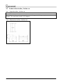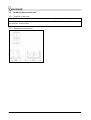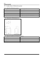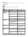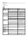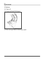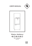
1
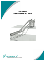
User Manual
Vencobelt 40 ALU
©2005 Vencomatic bv - User manual Vencobelt.
© 2005 Vencomatic ® B.V. – Nederland
All rights reserved.
The provided information can in no way be reproduced and/or published, in any form or
by any means (electronic of mechanical), without prior written permission from
Vencomatic ® B.V.
The provided information is based on general data concerning the -at the time of the
release known- constructions, material characteristic and work methods, so changes are
reserved.
The provided information is valid for the product in the standard type. Vencomatic ® B.V.
can therefore not be held responsible for damage resulting from a standard type deviant
specification of the product.
The provided information is made with all possible care, but Vencomatic ® B.V. cannot be
held responsible for errors or the results of errors in the information.
The by Vencomatic ® B.V. used usernames, trading names, trademarks, etc can according
to trading laws not be used.
Table of contents
Vencobelt 40 ALU............................................................................................................ 1
1 Foreword ................................................................................................................... 4
1.1
This manual....................................................................................................... 4
1.2
Manual .............................................................................................................. 4
1.3
Document codes................................................................................................ 4
1.4
Stickers on the machine..................................................................................... 5
1.5
Icons in this document ...................................................................................... 6
1.6
Available documentation ................................................................................... 6
1.7
List of terms ...................................................................................................... 7
1.8
Service and technical support ............................................................................ 8
1.9
Identification of the system ............................................................................... 8
1.10
The machine and the environment..................................................................... 8
1.11
Discard the machine .......................................................................................... 9
1.12
General safety instructions ................................................................................ 9
1.13
Taken safety measures for this machine .......................................................... 10
1.14
CE-marking, intended use................................................................................ 10
1.15
Warranty regulations ....................................................................................... 11
2 General description ................................................................................................. 12
2.1
Description Vencobelt ..................................................................................... 12
2.2
Purpose / use .................................................................................................. 12
2.3
Productspecifications....................................................................................... 12
3 Technical data ......................................................................................................... 13
3.1
Technical data drive unit ................................................................................. 13
3.2
Technical data section ..................................................................................... 14
3.3
Technical data corner ...................................................................................... 15
3.4
Technical data incline / decline set .................................................................. 16
3.5
Technical data return unit................................................................................ 17
3.6
Technical data oil lubrication system ............................................................... 18
4 Transport ................................................................................................................ 19
4.1
Transport safety regulations............................................................................ 19
5 Storage.................................................................................................................... 20
5.1
Storage safety regulations ............................................................................... 20
6 Operation ................................................................................................................ 21
6.1
Operation elements ......................................................................................... 21
6.2
Emergency stop ............................................................................................... 21
7 Settings ................................................................................................................... 22
7.1
Settings table .................................................................................................. 22
8 Maintenance ............................................................................................................ 23
9 Failure ..................................................................................................................... 24
9.1
Failure table .................................................................................................... 24
10
Options ........................................................................................................... 25
10.1
Paper roll......................................................................................................... 25
10.2
Corner with bend 0-180 degrees ..................................................................... 25
10.3
Drive unit type VB40ALU NEMA-flange / Japan ................................................. 25
11
Index............................................................................................................... 26
um-vblt-03-en
3
1 Foreword
1.1 This manual
This manual is made as a reference book for the machine that is mentioned on the cover
of this document. Only qualified users can use and maintain this machine in a safe way.
Keep the manual in the same place near the machine. If the manual gets lost order a new
one via your supplier.
This manual provides you with information about safety, technical specifications,
operation and maintenance. Take your time to read this document carefully before using
the machine.
The machine is developed with all care and meets the CE-marking. Therefore it is not
allowed to modify the machine.
The machine is inspected thoroughly before delivery to you.
Note the registration number of the machine. You can find this number on the
production label of the machine. Make sure to have this number at hand in case you
want to contact the service department of you supplier.
Vencomatic is not responsible for damage or injury caused by not following the
instructions mentioned in this manual.
1.2 Manual
Everyone working with or near the machine should know the contents of this manual.
Follow the instructions in the manual. The management should instruct the personnel
according to this document and follow all regulations and suggestions.
Never change the order of the to do actions.
Keep this manual during the lifetime of this machine in the same place near the machine.
The manual should be at the users disposal.
1.3 Document codes
The document code consists of six parts:
•
•
•
•
•
•
Field 1: document type
Field 2: product type
Field 3: version number
Field 4: language code
Field 5: month of publication
Field 6: year of publication
um-vblt-03-en
4
1.4 Stickers on the machine
Following stickers are applied to the machine. See picture below.
um-vblt-03-en
5
1.5 Icons in this document
In the manual of this machine the following icons are used:
Careful
Procedures that can cause damage to the product, surroundings or
environment. This damage can occur if procedures are not carried out
carefully.
Warning
Danger for electricity / electrical power.
Remarks, suggestions and advices.
Pull out the plug first before proceeding operation.
Consult the indicated Information source first.
Protect against water and moisture.
Watch out!
Procedure that needs extra attention.
1.6 Available documentation
The following documentation of the Vencobelt is available:
•
•
user manual (Vencobelt 01-en/August-2001)
installation manual (Vencobelt-01-en/August-2001)
um-vblt-03-en
6
1.7 List of terms
In this manual the following terms are used:
Technician
A trained -and therefore acquainted with the applied
technique- expert familiar with the possible dangers
of the machine. Technicians have a minimum age of
19 years. They have a solid knowledge of transport
techniques. Technicians are authorized to transport,
install, place in operation and repair the machine.
Authorized user
See 'User'. The 'authorized user' is also authorized to
install and commission the machine.
User
The customer using the machine according to the
purpose detailed in the concerning user manual. The
user is responsible for the operation and the in the
user manual described periodic adjustment, cleaning
and maintenance of the machine.
Conveyor belt system
Indication for all possible versions of this machine.
Component
Identification for every separate connectable part of
the machine.
Flock
Indication for the economic life cycle of the
chickens.
um-vblt-03-en
7
1.8 Service and technical support
When an item is not discussed in this manual contact your local Vencomatic dealer for
information about specific procedures.
1.9 Identification of the system
The production label is placed on the drive unit. See picture below.
The number on the production label represents the order number.
1.10 The machine and the environment
1.10.1 Packaging material
The packaging material mainly consists of:
•
•
•
(corrugated) cardboard
(untreated) wood
plastic packaging material
Inform the customer to inquire about the possibilities for recycling and environmentally
friendly disposal / re-use of the packaging materials.
um-vblt-03-en
8
1.11 Discard the machine
Discarded machines should be disposed of in an environmentally friendly way according
to the local regulations. The used materials can be subdivided roughly in:
•
•
•
•
•
•
plastic (egg carrier on chain, dirt tray, various plugs)
untreated metal (shafts)
coated metal (motor and bearing block)
galvanized metal (sheet metal, fastening materials, legs)
aluminum (side profiles of section)
oil and grease (in motor, bearing block and oil lubrication system)
If an electrical control panel is supplied:
The printed circuit board(s) and their components in the control panel are electrical
waste.
1.12 General safety instructions
Vencomatic B.V. will not accept any claim for damage or injury caused by not following
the safety regulations and safety instructions, or carelessness during:
•
•
•
•
•
•
transport,
installation,
commissioning,
operation,
maintenance,
troubleshooting and repair,
of the machine and possible accessories. Depending on specific working circumstances
or additional accessories, additional safety regulation can be needed. If during previous
the aforementioned activities a potential danger occurs, please contact Vencomatic B.V.
immediately.
1.12.1 Installation manual / user manual
•
•
•
•
Every technician has to know the contents of the installation manual. The technician
must follow the instructions in the installation manual conscientiously.
Every (authorized) user has to know the contents of the user manual and follow the
instructions in the user manual conscientiously.
Never change the order of the “to do” actions.
Store this manual carefully.
1.12.2 Stickers and instructions on the machine
Stickers, symbols and instructions are an integral part of this machine’s safety
precautions. It is therefore not allowed to cover them up and / or remove them. They
have to be present and legible during the whole life cycle of the system.
•
Replace or repair illegible stickers, symbols and instructions immediately.
um-vblt-03-en
9
1.12.3 Technician
Transport, installation and commissioning of the machine is allowed for authorized and
trained technicians only. (See 'Terms and Definitions'.) While carrying out their work they
are always fully responsible for compliance of local safety regulations and guidelines.
Temporary personnel and persons in training are allowed to work with the machine
under supervision of an authorized technician only.
1.12.4 Authorized users
An authorized user is the customer using the machine. This use is in accordance with the
purpose of the user guide. The user is responsible for the operation of the machine. The
user takes care of periodic adjustment, cleaning and maintenance of the machine. These
items are written down in the user manual.
The ‘authorized user’ is also authorized for installation and commissioning of the
machine.
1.12.5 Technical specifications
The technical specifications cannot be changed.
1.12.6 Modifications
Modification of (or parts of) the machine is not allowed. Use original (spare)parts advised
by the manufacturer only.
1.13 Taken safety measures for this machine
The following safety measure protections are present:
•
•
•
Guard for transfer brush on drive unit.
Warning stickers, see ‘Stickers on the machine’.
Electrical protection, see ‘Manual Electrical Control Panel’.
1.14 CE-marking, intended use
1.14.1 Machinery directive
The machine is constructed according to the machinery directive. Therefore the machine
is CE-marked.
CE-marking means that the machine at the time of delivery met the CE-requirements
applied to the machine at that moment. The responsibility for CE-conformity for the
machine expires entirely or partly and changes to the buyer if the following conditions
are not observed:
The CE-marking is applied only to the machine.
•
•
•
The machine can only be used in observance with the contents of this user manual.
The machine can only be used within the range of the products specifications.
The original state of the machine cannot be changed without written authorization of
Vencomatic B.V.
um-vblt-03-en
10
1.14.2 Purpose Vencobelt
The Vencobelt is a machine for transportation of eggs.
Every other or further use is not regarded conform the purpose. Vencomatic is not
responsible for damage or injury because of this. The machine is constructed according
to the valid requirements and standards. Use the machine only in technical perfect state,
conform previous mentioned purpose.
1.14.3 Use according to purpose
The "Use according to purpose" as recorded in the EN 292-1 is the use where the
technical product according to its specifications -including its possibilities according to
the sales brochure- is capable of. When in doubt this is the use that seems obvious
resulting from construction, type and function of the product. “Use according to
purpose” also includes following the instructions in the user guide.
1.15 Warranty regulations
The warranty regulations applied to the machine are recorded in the terms of delivery
and payment of Vencomatic BV, registered at the chamber of commerce in Eindhoven
with number 873/94.
The warranty has a validity of 12 months.
The warranty expires if:
•
•
•
•
•
•
The warranty validity is past 12 months.
Not authorized changes and / or modifications are applied to the machine.
Parts and consumer goods that are not supplied by the manufacturer are applied.
The maintenance is not carried out according to the indications in the manual.
The machine in not set up conform the guideline indicated by Vencomatic.
The machine is installed incompetently.
um-vblt-03-en
11
2 General description
2.1 Description Vencobelt
The Vencobelt is made up of modular components. This means that –depending on the
use of the component- different positions are possible.
•
•
The maximum capacity of the Vencobelt is 25,000 eggs per hour.
The belt speed is 4.5 meter/minute with the electric motor running at 50 Hz.
The following components can be part of the Vencobelt.
•
•
•
•
•
•
•
319500/6/7/10/11
:
drive unit
319501 :
section
319503 :
incline / decline set
319504/8/9
:
corner
319502 :
return unit
316634 :
oil lubrication system
949114 :
binder with bill of material and manuals
2.2 Purpose / use
The Vencobelt is designed for transportation of eggs. Because of the modularity it is
possible to make various arrangements, custom made to the local needs and
possibilities. Therefore the Vencobelt can be easily integrated in “house layouts”.
2.3 Productspecifications
Only chicken- and turky eggs can be transported with this machine.
um-vblt-03-en
12
3 Technical data
3.1 Technical data drive unit
3.1.1 General drive unit
Description
Torque
(Nm)
Max. effective Vencobelt
length
(m)
(ft)
VB40ALU 110 Nm
110
25
82
VB40ALU 210 Nm
210
50
164
VB40ALU 310 Nm
310
100
328
VB40ALU NEMA-flange *
variable
75
246
VB40ALU Japan
310
100
328
* motor type to be installed after consultation with dealer.
3.1.2 Dimensions drive unit
All motor versions have the same dimensions.
um-vblt-03-en
13
3.1.3 Electrical installation drive unit
Description
Power
Mains voltage
VB40ALU 110 Nm
370 Watt
3x230 / 3x400 V
VB40ALU 210 Nm
550 Watt
3x230 / 3x400 V
VB40ALU 310 Nm
550 Watt
3x230 / 3x400 V
VB40ALU NEMA-flen*
0.5 hp
0.75 hp
550 Watt
1x230 V 60Hz
1x230 V 60Hz
3x230 / 3x400 V
VB40ALU Japan
* motor type to be installed after consultation with dealer.
Electrical data is subject to changes.
3.2 Technical data section
3.2.1 General section
Description
General
Material
Aluminum
3.2.2 Dimensions section
um-vblt-03-en
14
3.3 Technical data corner
3.3.1 General corner
Description
Angle of corners
Corner VB40ALU 90 degrees
90 degrees
Corner VB40ALU 45 degrees
45 degrees
Corner VB40ALU degrees
0-90 degrees
3.3.2 Dimensions corner
um-vblt-03-en
15
3.4 Technical data incline / decline set
3.4.1 General incline / decline set
Description
An incline / decline set always contains an inclining, a declining component and a
plough. The maximum angle is 28 degrees.
3.4.2 Dimensions incline / decline set
um-vblt-03-en
16
3.5 Technical data return unit
3.5.1 General return unit
Description
On the return unit a rotating cleaning brush is mounted. The cleaning brush cleans the
egg carriers on the chain.
3.5.2 Dimensions return unit
um-vblt-03-en
17
3.6 Technical data oil lubrication system
3.6.1 General oil lubrication system
Description
Quantity / unit
Manufacturer
Buijer
Qmax
0,01 cc/minute
Pmax
4,1 bar
Volume oil reservoir
1.8 liter
Oil type
Paraffinum perliquidum PH. EUR. 99
3.6.2 Dimensions oil lubrication unit
3.6.3 Electrical installation oil lubrication system
Description
Unit
Frequency
50/60 Hz
Voltage
230 Volt
Capacity
Max. 3 Watt
um-vblt-03-en
18
4 Transport
4.1 Transport safety regulations
See also 'General safetyprescription and -instructions '.
um-vblt-03-en
19
5 Storage
5.1 Storage safety regulations
•
•
•
•
•
See also 'General safety instructions'.
Respect the surrounding conditions. Never store the system in a room where the
temperature can get under +10 °C. Lower temperatures can damage sensitive parts.
Store the system in a dry and dust free room.
Place the system on a level floor.
Never place heavy products on top of lighter products.
um-vblt-03-en
20
6 Operation
6.1 Operation elements
The machine is operated from the central
control panel.
6.1.1 Operating the oil lubrication system
The amount of lubricant delivered for each
stroke of the piston is adjustable from
1cm² to 5cm².
Adjustment is made by raising the collar
with indicator window and turning manual
feed knob and collar.
The chain always has to be greasy, this is
the responsibility of the owner/user.
There always has to be sufficient oil in the
reservoir, this is the responsibility of the
owner/user
Electrical data is subject to changes.
6.2 Emergency stop
On the electrical control panel there is an
emergency stop.
See also ‘Manual Electrical Control Panel’
for further information.
um-vblt-03-en
21
7 Settings
7.1 Settings table
Disconect all electrical connections before proceeding operation.
Frequency
What to do
Settings after run in period*
Check if all the components of the machine are well
aligned and leveled to each other: the chain should
run evenly.
Check if the nut of the adjustable foot is fastened. If
not: check if the height is correct and fasten the nut.
Check if the bearings run smooth.
Tighten chain: see ‘tighten chain’.
Join chain ends: see ‘join together chain ends’.
Settings during ‘in operation’
situation
Adjusting the oil lubrication system: see ‘operating
the oil lubrication system’. Attention! Never close
the oil reducing valve of the oil lubrication system
while pump is in operation.
Adjusting timer of oil lubrication system: see
‘Manual Electrical Control Panel’.
Tighten chain: see ‘tighten chain’
Monthly settings
Check if all the components of the machine are well
aligned and leveled to each other: the chain should
run evenly.
Setting after one flock
Check if all the components of the machine are well
aligned and leveled to each other: the chain should
run evenly.
Check if the nut of the adjustable foot is fastened. If
not: check if the height is correct and fasten the nut.
Check if the bearings run smooth
Tighten chain: see ‘tighten chain’
Join chain ends: see ‘join together chain ends’
•
The run in period is past when it is not necessary to tighten the chain anymore.
um-vblt-03-en
22
8 Maintenance
Disconect all electrical connections before proceeding operation.
Always check if the electrical connections are dry after cleaning.
Frequency
What tot do
Where on the machine
After installation
Check the oil level of the motor On drive unit
Production
depending
maintenance
Remove feathers from brushes, On drive unit, return unit and
rotating brushes and shafts
shafts on remaining
components
Daily check and
maintenance
Spray chain clean highpressure
cleaner
Near return unit. Watch out!
Do not spray on bearings. Let
the system run during
spraying
Clean the electrical part with a
moisten cloth and domestic
soap
Motor drive unit and oil
lubrication unit
Clean motor fan
With compressed air
Empty litter bin
Near drive unit and return
unit
Visualy check oil level of the oil Near drive unit
lubrication system: the level
has to be between the upper
and the lower marking
Check if the chain is greasy
enough
Whole chain
Monthly
maintenance
Check on wear and tear,
centering of the parts
Drive wheels, transport
chain, chain-closing link,
green plastic parts on the
corners, bends and egg
carriers
Yearly maintenance
/ Maintenance after
one flock
Check the oil level of the motor On drive unit
um-vblt-03-en
Spray chain clean highpressure
cleaner
Near return unit. Watch out!
Do not spray on bearings. Let
the system run during
spraying
Clean the electrical part with a
moisten cloth and domestic
soap
Motor drive unit and oil
lubrication unit
23
9 Failure
9.1 Failure table
Disconect all electrical connections before proceeding operation.
Failure
Cause
Solution
Chain slips near
drive wheel
Chain is to loose
Tighten chain. See ‘Tighten
chain’
Chain wheel worn out
Replace chain wheel
Chain worn out
Replace chain
Eggs are greasy
Too much grease on transport chain Regulate amount of grease.
See ‘Settings table’
Eggs are dirty
Transfer brushes are dirty
Clean brushes with water
and domestic soap
Eggs are broken
Broken or missing egg carriers
Replace egg carriers
Machine is not leveled correct, egg
carriers stick
Level machine
Transfer is badly adjusted or broken Adjust or replace transfer
Egg supply is to big
Motor drive unit
runs heavily
Decrease egg supply
Oil lubrication system is switched of Switch on oil lubrication
unit See: ‘Operating the oil
lubrication system’
Out of oil
Check oil level, if necessary
refill
Out of oil motorreductor / oil level
too low
Check oil level, if necessary
refill
Brushes return
unit don’t run
Geared belt is loose or worn
Tighten geared belt or fix
and tighten geared belt
again
Machine will not
start after
cleaning or
installation
Chain is too dry
Oil the chain with a hand
brush
Eggs get broken
in a corner
Egg supply is too big
Decrease egg supply
Eggs get broke in Egg supply is too big
the incline /
decline set
Decrease egg supply
Setting of incline / decline axis are
wrong
um-vblt-03-en
Place incline / decline axis
in highest position
24
10 Options
10.1 Paper roll
10.2 Corner with bend 0-180 degrees
10.3 Drive unit type VB40ALU NEMA-flange / Japan
um-vblt-03-en
25
11 Index
Authorized user .............................................................................................................. 7
Chicken eggs................................................................................................................. 12
Component ..................................................................................................................... 7
Conveyor belt system ...................................................................................................... 7
Corner........................................................................................................................... 25
technical data............................................................................................................. 15
Discard............................................................................................................................ 9
Document codes ............................................................................................................. 4
Drive unit ...................................................................................................................... 25
technical data............................................................................................................. 13
Emergency stop............................................................................................................. 21
Failure ........................................................................................................................... 24
Failure table .................................................................................................................. 24
Flock ............................................................................................................................... 7
Guarantee regulations ................................................................................................... 11
Icons ............................................................................................................................... 6
Identification of the system ............................................................................................. 8
Incline / decline set
technical data............................................................................................................. 16
List of terms.................................................................................................................... 7
Machine
discard......................................................................................................................... 9
Machinery directive ....................................................................................................... 10
Maintenance.................................................................................................................. 23
Modifications ................................................................................................................ 10
Oil lubrication system
operation ................................................................................................................... 21
Oil lubrication systen
technical data............................................................................................................. 18
Operation...................................................................................................................... 21
operation elements .................................................................................................... 21
Options ......................................................................................................................... 25
Packaging material .......................................................................................................... 8
Paper roll....................................................................................................................... 25
Production label .............................................................................................................. 8
Productspecifications .................................................................................................... 12
Purpose Vencobelt......................................................................................................... 11
Return unit
technical data............................................................................................................. 17
Safety instructions........................................................................................................... 9
Safety measures ............................................................................................................ 10
Section
technical data............................................................................................................. 14
Service ............................................................................................................................ 8
Settings......................................................................................................................... 22
table .......................................................................................................................... 22
Stickers ....................................................................................................................... 5; 9
Storage.......................................................................................................................... 20
Storage safety regulations ............................................................................................. 20
um-vblt-03-en
26
Technical data ............................................................................................................... 13
Technical specifications................................................................................................. 10
Technical support............................................................................................................ 8
Technician
responsibilities........................................................................................................... 10
Technician....................................................................................................................... 7
Transport ...................................................................................................................... 19
Transport safety regulations.......................................................................................... 19
Turky eggs .................................................................................................................... 12
User ................................................................................................................................ 7
responsibilities........................................................................................................... 10
Vencobelt
description................................................................................................................. 12
um-vblt-03-en
27