1
MOOG
User's Manual
for L180 digital servo drive
L180 User's Manual
PAGE 2 of 104
Rev. c 05/01
L180 User's Manual
Record of Manual Revision
Revision
Index
Date
Author
Description
Effectivity
a
13th April. 00
b
c
Joachim Heinrich
First Release
All
nd
Joachim Heinrich
Second Release
All
th
Joachim Heinrich
Third Release, including L180GUI 2.0 and firmware A2
All
2 May 00
4 May 01
Copyright Information
=Copyright 2001 MOOG - All rights reserved
The information contained in this document is the property of MOOG GmbH and may not be reproduced or transmitted in any
form or by any means, electronic, mechanical, photocopying, recording or otherwise, nor stored in any retrieval system of any
nature without the express written authority of MOOG GmbH.
This manual is periodically reviewed and revised. These instructions have been written and checked to the best of our knowledge
and belief. However, MOOG GmbH assumes no responsibility for any errors or omissions in this document. Information in this
manual is subject to change without notice and does not represent a commitment on the part the MOOG Corporation.
Microsoft, Windows NT, Windows 95 and Windows 98 are registered trademarks of Microsoft Corporation.
Critical evaluation of the manual is welcomed. Your comments will assist us in future product documentation.
Rev. c 05/01
PAGE 3 of 104
L180 User's Manual
TABLE OF CONTENTS
1 DESCRIPTION AND TECHNICAL DATA
1.1
11
INTRODUCTION
11
DESCRIPTION
12
1.1.1
1.2
INSTRUCTIONS TO THE MANUAL
13
1.3
TECHNICAL DATA
14
1.3.1
DESIGN STANDARDS
14
1.3.2
MODEL NUMBER SELECTION
15
1.3.3
ACCESSORIES
16
1.3.4
GENERAL DATA
17
1.3.5
ELECTRICAL DATA
18
1.3.5.1
DRIVE RATINGS
18
1.3.5.2
POWER DISSIPATION
18
1.3.5.3
REGENERATION POWER
19
1.3.6
MECHANICAL DIMENSIONS
20
1.3.7
DRIVE OVERVIEW
21
1.3.8
DRIVE NAMEPLATE
22
PAGE 4 of 104
Rev. c 05/01
L180 User's Manual
2 SAFETY INSTRUCTIONS
23
2.1
QUALIFIED PERSONNEL
23
2.2
MAIN SAFETY INSTRUCTIONS
24
2.3
INFORMATION ON EMC
25
3 SERVOMOTORS
3.1
MOUNTING AND INSTALLATION
27
27
3.1.1
MOTOR NAMEPLATE
27
3.1.2
MOTOR INSTALLATION GUIDELINE
28
3.1.3
BEARING LOAD CAPACITY
29
3.1.4
COUPLING
32
3.1.5
RUNOUT
33
3.2
TECHNICAL MOTOR DATA
34
3.2.1
STANDARDS FOR MOOG MOTORS
34
3.2.2
MOTOR PERFORMANCE DATA
37
3.2.3
TORQUE SPEED CHARACTERISTIC G400 SERIES MOTORS
39
3.2.4
TORQUE-SPEED-CHARACTERISTICS G300 SERIES MOTORS
43
3.2.5
MOTOR BRAKE DATA
45
Rev. c 05/01
PAGE 5 of 104
L180 User's Manual
4 INSTALLATION
47
4.1
WIRING
47
4.2
CONNECTOR OVERVIEW
48
4.2.1
MOTOR AND POWER CONNECTOR TB1
49
4.2.1.1
TB1 POWER CONNECTOR PINOUT
52
4.2.1.2
ACCESSORY POWER PART
52
RESOLVER CONNECTOR J1
54
4.2.2
4.2.2.1
ACCESSORY RESOLVER PARTS
55
4.2.3
SERIAL PORT CONNECTOR J2
56
4.2.4
AXIS SIGNALS CONNECTOR J3
57
4.2.5
ENCODER SIMULATION CONNECTOR J4
60
4.2.6
LOGIC POWER CONNECTOR J5
62
5 L180 GRAPHICAL USER INTERFACE
63
5.1
SYSTEM REQUIREMENTS
63
5.2
GUI INSTALLATION
63
5.3
SYSTEM INFORMATION
64
5.4
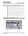
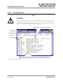
USING THE L180GUI
64
5.4.1
TOOLBAR
65
5.4.2
QUICK START
66
PAGE 6 of 104
Rev. c 05/01
L180 User's Manual
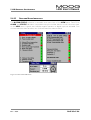
5.4.3
GENERAL INSTRUCTIONS
67
5.4.4
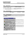
SERIAL LINK
69
5.4.5
PARAMETER FILE DOWNLOAD
69
5.4.6
PARAMETER SETTING
70
5.4.6.1
ADJUST OPTIONS
71
5.4.6.2
ENCODER SIMULATION CONFIGURATION
74
5.4.6.3
SPEED LOOP TUNING
76
5.4.6.4
CURRENT LOOP TUNING
81
5.4.6.5
MOTOR PARAMETERS
83
5.4.7
AUTOMATIC COMMAND MODE (FUNCTION GENERATOR)
86
5.4.8
UPLOAD OF PARAMETER FILES
88
5.4.9
SCOPE
89
5.4.10
FIRMWARE UPGRADE
90
5.4.11
EDIT PARAMETER FILE
91
5.4.12
PRIVILEGED ACCESS
92
5.4.13
SOFTWARE DRIVE RESET
92
5.4.14
SOFTWARE PREFERENCES
92
5.4.15
DRIVE AND MOTOR INDICATIONS
93
Rev. c 05/01
PAGE 7 of 104
L180 User's Manual
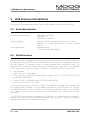
6 SYSTEM DESCRIPTION
95
6.1
SERVO STOP
95
6.2
DISPLAY INDICATION
96
6.2.1
REGULAR INDICATION
96
6.2.2
WARNING INDICATION
96
6.2.3
ALARM INDICATION
97
6.2.4
ALARM HANDLING
97
6.3
TROUBLE SHOOTING GUIDE
98
6.3.1
DRIVE RESET
101
6.3.2
OTHER PROBLEM SOURCES
102
6.4
FAILURE REPORT
PAGE 8 of 104
103
Rev. c 05/01
L180 User's Manual
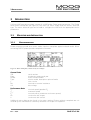
TABLE OF FIGURES
Figure 1: Maximum Regeneration Capability ............................................................................................ 19
Figure 2: Dimensions front and side......................................................................................................... 20
Figure 3: Installation and drill plan ........................................................................................................... 20
Figure 4: Drive Overview.......................................................................................................................... 21
Figure 5: Drive Nameplate ....................................................................................................................... 22
Figure 6: Motor Nameplate (values merely as example) ............................................................................ 27
Figure 7: Radial Load Capacity Gxx2 ........................................................................................................ 29
Figure 8: Radial Load Capacity Gxx3 ........................................................................................................ 30
Figure 9: Radial Load Capacity Gxx4 ........................................................................................................ 30
Figure 10: Radial Load Capacity G4x5 ...................................................................................................... 31
Figure 11: Motor Load Coupling .............................................................................................................. 32
Figure 12: Runout.................................................................................................................................... 33
Figure 13: Concentricity Figure 14: Perpendicularity ............................................................................... 33
Figure 15: Torque-Speed Char. G2L05 Figure 16: Torque-Speed Char. G2L10 ....................................... 39
Figure 17: Torque-Speed Char. G2L20 Figure 18: Torque-Speed Char. G2L40 ....................................... 39
Figure 19: Torque-Speed Char. G3L05 Figure 20: Torque-Speed Char. G3L15 ....................................... 40
Figure 21: Torque-Speed Char. G3L25 Figure 22: Torque-Speed Char. G3L40 ....................................... 40
Figure 23: Torque-Speed Char. G4L05 Figure 24: Torque-Speed Char. G4L10 ....................................... 41
Figure 25: Torque-Speed Char. G4L20 Figure 26: Torque-Speed Char. G4L40 ....................................... 41
Figure 27: Torque-Speed Char. G4L60 ..................................................................................................... 41
Figure 28: Torque-Speed Char. G5L10 Figure 29: Torque-Speed Char. G5L20 ....................................... 42
Figure 30: Torque-Speed Char. G5L30 Figure 31: Torque-Speed Char. G5L50 ....................................... 42
Figure 32: Torque-Speed Char. L2L10 Figure 33: Torque-Speed Char. L2L20 ........................................ 43
Figure 34: Torque-Speed Char. L3L15 Figure 35: Torque-Speed Char. L3L25 ........................................ 43
Figure 36: Torque-Speed Char. L4L10 Figure 37: Torque-Speed Char. L4L20 ........................................ 44
Figure 38:Current/time and torque/time diagrams.................................................................................... 45
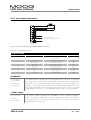
Figure 39: Wiring Overview ..................................................................................................................... 48
Figure 40: TB1 Wiring.............................................................................................................................. 50
Figure 41: Multi Axis Wiring .................................................................................................................... 51
Figure 42: Resolver wiring, DSUB 9 male cable to J1 ................................................................................ 54
Figure 43: Serial link wiring, DSUB9 female cable to J2 and PC................................................................. 56
Figure 44: J3 Axis Signals Wiring, DSUB25 male cable to J3 ..................................................................... 57
Figure 45: Encoder Output, DSUB15 male cable to J4 .............................................................................. 60
Figure 46: Definition of Encoder Signals, viewed from the shaft side ........................................................ 60
Figure 47: J5 Logic Power Wiring, DSUB15 female cable to J5 ................................................................. 62
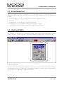
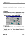
Figure 48: Main Window ......................................................................................................................... 64
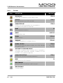
Figure 49: Parameters Setting .................................................................................................................. 66
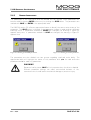
Figure 50: Warning for ENTER parameters Figure 51: Warning for SAVE parameters .............................. 67
Figure 52: GUI dialog box features........................................................................................................... 68
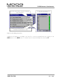
Figure 53: Setting Serial Port.................................................................................................................... 69
Figure 54: Parameter Download .............................................................................................................. 70
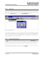
Figure 55: Setting Adjust Options ............................................................................................................ 71
Figure 56: Command Slope ..................................................................................................................... 73
Figure 57: Encoder Simulation Configuration ........................................................................................... 74
Figure 58: Encoder Signals....................................................................................................................... 76
Figure 59: Adjust Speed Loop Parameters ................................................................................................ 76
Rev. c 05/01
PAGE 9 of 104
L180 User's Manual
TABLE OF FIGURES
Figure 60: Speed Loop Regulator ............................................................................................................. 77
Figure 61: Speed Step, proportional gain ................................................................................................. 80
Figure 62: Speed Step, integral gain......................................................................................................... 80
Figure 63: Adjust Current Loop Parameters.............................................................................................. 81
Figure 64: Current Loop Regulator........................................................................................................... 82
Figure 65: Motor Parameters ................................................................................................................... 84
Figure 66: Warning during automatic command mode start-up ............................................................... 86
Figure 67: Automatic command mode..................................................................................................... 86
Figure 68: Warning after quit of the automatic command mode.............................................................. 87
Figure 69: Warning analog command applied.......................................................................................... 87
Figure 70: Parameter Upload ................................................................................................................... 88
Figure 71: Notes of parameter files .......................................................................................................... 88
Figure 72: Scope...................................................................................................................................... 89
Figure 73: Firmware Upgrade .................................................................................................................. 90
Figure 74: Parameter File Editor ............................................................................................................... 91
Figure 75: Preferences ............................................................................................................................. 92
Figure 76: Drive GUI Indications............................................................................................................... 93
Figure 1: End switch Configuration for servo stop, connector J3 .............................................................. 95
Figure 2: Definition of sense of rotation, viewed from the shaft ............................................................... 96
Figure 79: A1 firmware operation power module
Figure 80: A1 firmware Monitoring relay ................ 98
Figure 81: A2 firmware Monitoring relay
Figure 82: A2 firmware operation power module ................ 99
PAGE 10 of 104
Rev. c 05/01
1 Description and Technical Data
1
1.1
L180 User's Manual
DESCRIPTION AND TECHNICAL DATA
INTRODUCTION
The L180 servo drive is intended to control MOOG brushless servo motors. These are 3 phase
motors with 8 or 12 poles (4 or 6 polepairs) equipped with a two pole resolver.
The L180 servo drive is fully digital. High-performance torque and speed control fulfill all
requirements for fast response and high control accuracy.
Digital control allows comprehensive diagnostics, motor parameters tuning, data and fault
detection, etc... using a PC based Graphical User Interface (GUI).
Rev. c 05/01
PAGE 11 of 104
L180 User's Manual
1.1.1
1 Description and Technical Data
DESCRIPTION
The features of the L180 servo drive are described below:
Power supply
•
•
•
•
Single axis unit incorporating regeneration module minimizing wiring and space
requirements.
230V three phase or single phase.
Option: External filters in power source for CE compliance.
Drive designed according protective extra low voltage standards (PELV). An
autotransformer is sufficient for the main power input.
Power driver
•
•
•
Galvanic isolation between control and power electronics.
IGBT output stage.
Digital PWM current loop providing low ripple motor currents and high motor
efficiency.
Digital controller
•
•
•
•
•
•
Full-digital servo drive for brushless motor with resolver.
Easy software download through RS232 serial link.
Temperature regulated fan-cooling.
Multi loop control (torque and speed).
Sinusoidal current output ensures smooth torque and performance at low speed.
7 segment status indicator for diagnostic display.
User's inputs
•
•
•
•
± 10VDC differential analog input for speed or current command.
RS232 serial port.
Limit switches for overrun protection in both directions.
Optional external 24VDC power supply to the control and interface boards in case of
main power supply interruption.
User's outputs
•
•
Programmable incremental encoder output simulation with resolution from 1 to 2048
ppr (extrapolation), differential RS 422 line driver outputs.
Programmable monitoring relay to indicate ready, alarm or enable status.
Protections
•
•
•
Power stage protected against short-circuit and over-temperature.
Motor thermal protection by I²t limitation and thermistor.
Detection of resolver fault, motor wiring failure.
PAGE 12 of 104
Rev. c 05/01
1 Description and Technical Data
1.2
L180 User's Manual
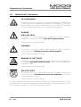
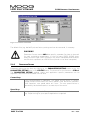
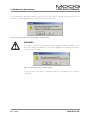
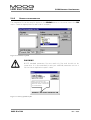
INSTRUCTIONS TO THE MANUAL
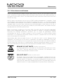
CE-COMPLIANCE
The symbol on the left indicates where a particular application-related safety
or EMC requirement is driven by the need for CE-Compliance of the L180
when installed in the system. Customers who do not need CE-Compliance
on their machinery may choose not to implement these features.
DANGER
HIGH VOLTAGE
The symbol on the left indicates high voltages which can be extremely
dangerous or lethal if touched and may result in personal injury.
These instructions must be followed.
WARNING
The symbol on the left is used to draw attention to safety instructions
concerning potential damage to the servo drive and motor.
These instructions must be followed.
BEWARE OF HOT PARTS
The symbol on the left indicates hot parts which can be dangerous if
touched and may result in personal injury. These parts must be protected
to prevent contact.
These instructions must be followed.
DELICATE PART
The symbol on the left is used to draw attention to installation instructions
concerning potential damage to the servo drive and motor. These parts
must be handled with care.
These instructions must be followed.
This user’s manual is written with the intention to supply all necessary information for servo
drive applications. In any case of uncertainty of the drive reaction or missing information, please
do not hesitate to contact your local MOOG application engineer.
Rev. c 05/01
PAGE 13 of 104
L180 User's Manual
1.3
1 Description and Technical Data
TECHNICAL DATA
1.3.1
DESIGN STANDARDS
The low voltage circuits of the L180 drive are designed as protective extra low voltage circuits
(PELV) thus an autotransformer can be used for the main line voltage.
Table 1: Drive Design Standards
Code
Year
Description
1998
EMC Directive
IEC 61800-3
1996-06
adjustable speed electrical power drive systems EMC product standard
EN 50082-2
1995-03
generic immunity standard
IEC 61000-4-2
1995
electrostatic discharge immunity test
IEC 61000-4-3
1995
radiated radio-frequency electromagnetic field immunity test
IEC 61000-4-4
1995
electrical fast transient, burst immunity test
IEC 61000-4-5
1995
surge iumminity test
1995
iummunity to conducted disturbances, induced by radio-frequency fields
1993-08
generic emission requirements
89/366/EEC; 98/13/EEC
IEC 61000-4-6
EN 50081-2
EN 50081-2
Group 1, Class A, conductive emission requirements (0.15 to 30 MHz)
EN 50081-2
Group 1, Class B, radiated emission requirements (30 to 1000 MHz)
EN 50178
1997-10
electronic equipment for use in power installations
73/23/EEC; 93/68/EEC
1993-02
low voltage directive
PAGE 14 of 104
Rev. c 05/01
L180 User's Manual
1 Description and Technical Data
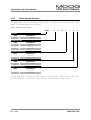
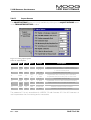
1.3.2
MODEL NUMBER SELECTION
The L180 family uses a 12 character coding system to identify the unique attributes of each
model. The coding system is shown Table 2.
Table 2: Model Number Selection
L180
-
x
1
0
x
-
x
x
PRODUCT
CODE
DESCRIPTION
L180
L180 Series
CURRENT RATING
CODE
DESCRIPTION
3
5/10 Arms
4
10/20 Arms
5
15/35 Arms
HARDWARE REVISION
CODE
DESCRIPTION
A
first release
B
second release
FIRMWARE
CODE
DESCRIPTION
A
± 10VDC Firmware
FIRMWARE REVISION
CODE
DESCRIPTION
1
first release
2
second release
Possible drive model numbers are L180-310A-A1, L180-410A-A1, L180-510A-A1, L180-310AA2, L180-410A-A2, L180-510A-A2, L180-310B-A2, L180-410B-A2 or L180-510B-A2.
Rev. c 05/01
PAGE 15 of 104
L180 User's Manual
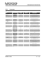
1.3.3
1 Description and Technical Data
ACCESSORIES
Table 3: Accessories
Part Number
Length
Motor
Description
L180 Manual
Part
C08476-001
-
-
L180 User's Manual, english version
L180GUI
Installation Disk
C08478-001
C08478-002
obsolete
-
Visual Indication Sticker
C08499-001
-
-
Raw Power Cable
note ➼
B47890-001
Gxx2, Gxx3, Gxx4
Raw Power Cable
note ➼
B47903-001
Motor Power Connector
A63472-001
available in
customary lengths
available in
customary lengths
-
Gxx2, Gxx3, Gxx4
Motor Power Connector
C08365-001
-
Gxx2, Gxx3, Gxx4
Motor Power Connector
B47736-001
-
G4x5
C08336-001-010
10m
Gxx2, Gxx3, Gxx4
C08336-001-020
20m
L180 Windows based
Graphical User Interface (L180GUI),
Motor parameter files
Sticker which explains in short terms the
7 segment display indication. Supplied
with each drive, spare part.
Shielded cable for customer
configuration
Shielded cable for customer
configuration
Power connector for customer
configuration, smallest version
Power connector for customer
configuration, easier to assemble
Power connector for customer
configuration
Prefabricated motor cable with mating
motor connector and ferrule ended leads
B47915-001-010
10m
B47915-001-020
20m
C08475-001
Motor Power Cable
Motor Power Cable
G4x5
G4x5
Prefabricated motor cable with mating
motor connector and ferrule ended leads
5m
-
C08335-003-010
10m
all motors
C08335-003-020
20m
Commisioning cable between PC and
drive
Prefabricated signal cable with mating
di
d
Drive mating power conn
C08474-001
-
-
Raw signal cable
note ➼
B47885-001
all motors
Motor mating signal conn
C08485-001
available in
customary lengths
-
L180 connector kit 1
C53106-001
-
-
L180 connector kit 2
C53107-001
-
-
L180 connector kit 3
C53108-001
-
-
Serial Port RS232 cable
Signal Cable
all motors
Mating power connector for all drives.
Supplied with each drive, spare part.
Shielded cable for customer
configuration
Signal connector for customer
configuration
Solder cup kit for use with 10 in
clearance cabinet, contains J1, J3, J4, J5
mating connector
Solder cup kit for use with 12 in
clearance cabinet, contains J1, J3, J4, J5
mating connector
Screw terminal kit for use with 12 in
clearance cabinet, contains J1, J3, J4, J5
mating connector
note ➼: consult local sales office
PAGE 16 of 104
Rev. c 05/01
L180 User's Manual
1 Description and Technical Data
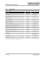
1.3.4
GENERAL DATA
Table 4: General Data
Description
Unit
L180
Backup Voltage
VDC
24 (20 -28)
Supply Voltage line to line, three and single phase
VAC
230 +10% -20%
Supply frequency
Hz
45 to 65
Operating temperature range
°C
0 to 60
°C
0 to 50
Operating temperature range at full power (from 50°C, reduce output
current by 2%/°C to 60°C)
Storage temperature range
°C
-20 to +70
kHz
7,5
Differential input reference
V
+ 10 to -10
Continuous regeneration power
W
300
Output frequency to motor
Hz
0 to 500
Incremental encoder simulation
ppr
1 to 1024 (2048)
Theoretical max. speed for motor with resolver "speed one"
rpm
7500
ON-Switching threshold of regeneration resistor
VDC
385
PWM chopper frequency
OFF-Switching threshold of regeneration resistor
VDC
380
ON-Trip threshold of DC-BUS overvoltage
VDC
410
OFF-Trip threshold of DC-BUS overvoltage
VDC
400
OFF-Trip threshold of DC-BUS undervoltage
VDC
230
ON-Trip threshold of DC-BUS undervoltage
VDC
220
Baud rate, fixed
Bd.
Transmission
1 START bit, 8 DATA bit,
no parity, 1 STOP bit
IP20
Serial Link Format
International Protection
Indicative weight
Dimensions (Width,Depth,Height)
9600
Full duplex
kg
3.2
mm
76.5, 200, 295
Units in VAC are root mean square (rms) values.
Rev. c 05/01
PAGE 17 of 104
L180 User's Manual
1.3.5
1 Description and Technical Data
ELECTRICAL DATA
1.3.5.1
DRIVE RATINGS
Table 5: Drive Power Ratings
3~ main line
continuous current
maximum current
Unit
L180-310A
L180-410A
L180-510A
Arms
5
10
15
Apeak
7
14
21
Arms
10
20
36
Apeak
14
28
50
continuous power
kW
2
4
6
maximum power
kW
4
8
14
Single phase operation causes a power reduction to 1/3 of the power rating above
Conversion formula:
I rms =
I peak
1.3.5.2
U rms = 230Vrms
2
P = 3 ⋅ I rms ⋅ U rms
POWER DISSIPATION
The power dissipation can be computed with the following formula:
Pdisp [W ] = 9 ∗ I rms + 20 + Pbrake
Pdisp: total power dissipation in Watt
9: calculation constant in Watt per Arms
Irms: continuous current to the motor in Arms
20: power dissipation under no load conditions in Watt
Pbrake: actual regeneration power of the resistor in Watt
PAGE 18 of 104
Rev. c 05/01
L180 User's Manual
1 Description and Technical Data
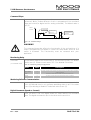
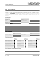
1.3.5.3
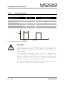
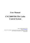
REGENERATION POWER
Table 6: Regeneration Power Rating
Regeneration power
Unit
for all L180 drives
Ω
39
maximum regeneration power
W
3800
continuous regeneration power
W
300
maximum ON-time at max. regen power
ms
60
s
1
regeneration Resistor
minimum period at max. ON-time
Pmax
ON-time
period
t
Figure 1: Maximum Regeneration Capability
WARNING
The maximum and continuous regeneration power of the drive is limited. An
external regeneration resistor or DC-BUS terminal is not available. The
regeneration power requirements of the application must meet with the
drive capabilities.
If the application regeneration power is above the maximum drive
regeneration power an overvoltage alarm will occur immediately. If the
application regeneration power is above the continuous drive regeneration
power an overheating alarm will occur after a certain period of time. This
time depends on the continuous regeneration power.
For calculation of regeneration power for your specific application please get
in contact with your local MOOG application engineer.
Rev. c 05/01
PAGE 19 of 104
L180 User's Manual
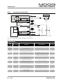
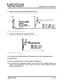
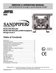
1.3.6
1 Description and Technical Data
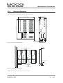
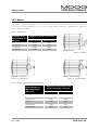
MECHANICAL DIMENSIONS
Dimensions are in millimeter (and inches in brackets)!
252.2 (9.93)
MOOG
295 (11.6)
13.25 (0.522)
200 (7.88)
38.25 (1.51)
76.5 (3.01)
Figure 2: Dimensions front and side
50 (1.97)
MOOG
MOOG
MOOG
280.5 (11.04)
MOOG
252.5 (9.94)
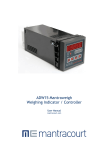
DRIVE ARRANGEMENT
3 x ∅ 5.5 (0.217)
or M5
84 (3.31)
10 (0.394)
25 (0.984)
AIR FLOW
Figure 3: Installation and drill plan
note ➼: 100 mm (3.94 in) top and bottom clearance required!
PAGE 20 of 104
Rev. c 05/01
1 Description and Technical Data
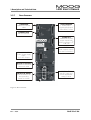
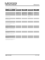
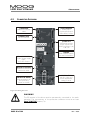
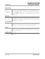
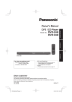
1.3.7
L180 User's Manual
DRIVE OVERVIEW
J1 RESOLVER
Terminal for resolver
cable
J3 AXIS SIGNALS
Analog Input
Digital Input/Output
Status Relay Contact
J2 SERIAL PORT
RS 232 Interface
J4 ESM OUT
Differential encoder
output signals from
RS422 line driver, A, A,
B, B, Z, Z
J5 LOGIC POWER
24 VDC Power Supply
Input,
± 15 VDC Output
STATUS
seven segment display
for status information
TB1 power connector
Terminal for main lines
and motor cable
PROTECTIVE EARTH
Screw terminal for PE
and grounding
(screw not visible)
REGEN ACTIVE
red LED, lights up if
motor regenerates
energy to drive
Figure 4: Drive Overview
Rev. c 05/01
PAGE 21 of 104
L180 User's Manual
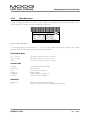
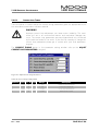
1.3.8
1 Description and Technical Data
DRIVE NAMEPLATE
Please compare received servo drive model listed on nameplate against ordered model. When
contacting MOOG please provide nameplate information.
Model No.
Serial No.
MOOG
Servo drive
------------- I n p u t ------------Voltage
UN[Vrms~]
230
Frequency
f [Hz]
50/60
Line
[Phase]
3~/1~
Protection
IP 20
--- O u t p u t ( M o t o r ) --DC Bus
Udc[Vdc]
Con. CurrentIN[Arms~]
Max. CurrentImax[Arms~]
Power
PN[kW]
Detailed information see instruction manual
Made
in ITALY
Figure 5: Drive Nameplate
The barcode above the nameplate in 3 of 9 style (also called barcode 39) contains the model
and the serial number segregated by a space bar character.
Performance Data
Con. Current
Max. Current
Power
continuous output current to motor
maximum output current to motor
nominal continuous power to motor
General Data
Voltage
Frequency
Line
Serial No.
Model No.
DC BUS
Line phase to phase voltage
line frequency
Line number of phases
Serial number
Model number, see table 2
internal DC BUS voltage
Standards
Protection
CE
PAGE 22 of 104
Degree of international protection
Conformity certificate will be supplied on request
Rev. c 05/01
2 SAFETY INSTRUCTIONS
2
2.1
L180 User's Manual
SAFETY INSTRUCTIONS
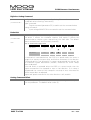
QUALIFIED PERSONNEL
WARNING
The components making up the drive system may only be installed and
serviced by qualified personnel. The local regulations for accident
prevention, electronic devices, electric installations and machinery must be
observed.
Unqualified work on the drive components and failure to comply with the warnings contained
in this manual or affixed to the components can be lethal or cause damage to property.
The work permitted within the scope of this manual may consequently only be undertaken by
qualified personnel.
This includes the following people:
• planning and engineering design personnel familiar with the safety guidelines for
measurement, electronic devices, machinery equipment, electric installations and control
instrumentation,
• operating personnel who have been instructed with regard to the handling of electronic
devices, machinery equipment, servo drives and who are familiar with the operating
instructions contained in this manual,
• commissioning and service personnel authorized to start up, ground and mark these
systems in accordance with safety engineering standards. These persons must be qualified
service personnel according to the local regulations.
The design standards offer additional information about the safety of the L180 servo drive.
Rev. c 05/01
PAGE 23 of 104
L180 User's Manual
2.2
2 SAFETY INSTRUCTIONS
MAIN SAFETY INSTRUCTIONS
DANGER
HIGH VOLTAGE
The servo drives operate with potentially lethal voltages.
For this reason:
• Disconnect the system from the mains supply.
Before starting any work on the drive system, it must be disconnected
from the main voltage and secured against inadvertent reconnection by
means of the disconnect switch. Do not remove the plugs for the motor
and mains supply while the L180 servo drive is connected to mains
power.
• The servomotor must come to a complete stop.
Rotating servomotor can generate potentially lethal voltages by acting as
generator.
• It is NOT sufficient to simply disable the drive.
DANGER
HIGH VOLTAGE
The capacitors in the servo drive may still be charged.
For this reason:
• Note the discharge time of the capacitors.
The servo drive contains capacitors which may be charged up to
410 VDC. Wait at least 5 minutes for the capacitors to discharge after
disconnecting the main voltage.
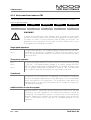
WARNING
The servo drive is designed for use in cabinets and has an IP 20 rating. A
cabinet is recommended which has an IP rating of at least IP54.
PAGE 24 of 104
Rev. c 05/01
2 SAFETY INSTRUCTIONS
L180 User's Manual
WARNING
BEWARE OF MECHANICAL HAZARDS!
Servomotors can accelerate highly dynamically. They also have enormous
torque. The following points must therefore be observed when starting the
system.
• The danger zone of the motor must be cordoned off.
The system must feature a safety guard to prevent personnel from
reaching into or entering the danger zone. If the safety system is tripped,
the drive system must be disconnected from the main voltage
immediately.
• Motor may accelerate inadvertently
The motor may accelerate inadvertently due to wiring faults or errors in
the application software. Appropriate safety precautions must be taken
to ensure that neither personnel nor machine components are
endangered in any way.
•
2.3
Coast stop
Any failure of the servo drive leads to a coast stop of the motor.
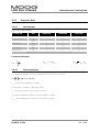
INFORMATION ON EMC
CE-COMPLIANCE
The information on EMC provided here contains general recommendations
to assist the machine manufacturer when installing L180 components made
by MOOG in finished products which must conform to the requirements of
EC Directive 89/336/EEC (EMC Directive). Although MOOG has exercised
utmost care in compiling these recommendations, we cannot accept any
liability whatsoever for claims associated with the user's individual
applications. This also applies with regard to non-performance, noncompliance, faults, misunderstandings and mistaken interpretation.
Responsibility for ensuring that every finished product containing these components conforms
to the requirements of the EMC Directive rests entirely with the machine manufacturer of the
finished product. MOOG cannot accept any liability whatsoever for finished products made by
other manufacturers and containing L180 components from MOOG.
Rev. c 05/01
PAGE 25 of 104
L180 User's Manual
2 SAFETY INSTRUCTIONS
EMC environment
The L180 components from MOOG are designed for installation in industrial equipment and for
operation in industrial areas. The L180 components from MOOG have therefore been tested in
accordance with the EMC standards, mentioned in the design standards.
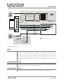
Installation of the components
All ground connections between the servo drive cover and the control cabinet must be securely
mounted to guarantee a continuous ground connection. The L180 servo drive is designed for
emission minimization to ensure secure connection between the drive and the baseplate in
conjunction with EMC requirements. The drive has to be connected with protective earth on the
earth stud to ensure proper grounding.
To ensure an optimum EMC shield, the control cabinet should have a continuous ground
connection between all metal panels (frame, side panels, top, baseplate, etc.). A control cabinet
which has been designed to provide an optimum EMC shield can be used for this purpose.
The machine manufacturer must design the system to prevent interference between
subsystems, modules, power supplies, and/or any other component. Furthermore, the complete
system must be designed such that there is no interaction between actual and potential sources
of interference. The machine manufacturer is responsible for taking suitable precautions to
minimize such interference. For example, safe distances must be maintained between
potentially interfering components in addition to the use of proper shielding. The machine
manufacturer is responsible for the design methods used to integrate all system components
together in order to prevent any interference. The machine manufacturer must decide which is
the most efficient method for the complete product.
Where possible, shielded cables with fully shielded connector housings should always be used.
The cable shield must be connected to the connector shields over the full 360° circumference in
order to ensure a continuous all-round ground connection. All cable connections to the servo
drive must be tightly secured. In particular, all screws in the ground connections of the
connector shields must be securely tightened. To avoid potential interference, power and signal
cables must be routed as far apart as possible in the control cabinet and on the entire finished
product. If power and signal cables must be crossed, the cables should be crossed perpendicular
to each other to minimize interference. The machine manufacturer of the complete product
must decide which is the most efficient method.
Further details on filtering, grounding and shielding can be found in this manual.
PAGE 26 of 104
Rev. c 05/01
L180 User's Manual
3 SERVOMOTORS
3
SERVOMOTORS
A Moog L180 servo drive system consists of a L180 and a Global series servomotor. The Global
series motor nameplate (see Figure 6) lists both the motor model and the motor's electrical
type. The motor electrical type can be used to configure the L180 with the appropriate motor
parameters.
3.1
MOUNTING AND INSTALLATION
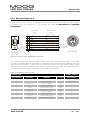
3.1.1
MOTOR NAMEPLATE
Please compare received servo motor model listed on nameplate against ordered model. When
contacting MOOG please provide nameplate information.
Figure 6: Motor Nameplate (values merely as example)
General Data
S/N:
Date:
Model:
Type:
J:
Rtt:
Ud:
serial number
production quarter and year
motor model number
electric model, description optional brake
rotor inertia
terminal to terminal resistance
bus voltage
Performance Data
nN:
nmax:
PN :
M0 :
I0:
nominal speed (speed at PN)
maximum speed
nominal power (maximum continuous power)
continuous stall torque
continuous stall current
Additional motor data can be found in the motor catalog. Devices without nameplate are not
covered by the manufacturer's warranty and must not be put into operation.
Rev. c 05/01
PAGE 27 of 104
L180 User's Manual
3 SERVOMOTORS
3.1.2 MOTOR INSTALLATION GUIDELINE
MOOG recommends that hexagon socket head screws to DIN 912 8.8 be used to secure the
motor. Assembly is made very much easier by using an Allen key with ball head, particularly in
the cases of motor sizes 2 and 3. The screws used to install these motor sizes must not be more
than 40 mm long.
MOOG motors can become very hot (up to 155°C winding temperature) in operation. Good
heat dissipation must therefore be ensured when installing the motor, i.e. it should be flanged
onto a suitably solid metal part of the machine. Adequate convection must also be ensured. In
individual cases, the motor must furthermore be protected against contact due to the risk of
burns. Forced cooling (e.g. with fans) will increase the continuous power, while bad convection
may decrease the continuous performance.
Before connecting a coupling to the motor shaft, the shaft must be thoroughly degreased.
When using a degreasing agent, care must be taken to prevent it entering the bearing.
Otherwise the bearings permanent lubrication can no longer be guaranteed. MOOG
recommends the use of a clamp coupling or shrink connection to ensure reliable torque
transmission. An inexpensive and service friendly connection is possible with the slot and key
option (ensure tight slot tolerances).
Impermissibly high axial and radial forces on the shaft can result in motor damage during
installation. The service life of the motor is impaired if the bearing is damaged in any way.
Adjusting the rotor shaft by force can impair the correct functioning of the optional brake to
such an extent that it has little or no braking effect. Excessive pressure and impacts on the front
end of the shaft and rear housing cover must therefore be avoided under all circumstances.
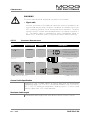
BEWARE OF HOT PARTS (sticker on servo motor)
In extreme applications, the surface of the servomotor may heat up to more
than 100 °C and can cause skin burns if touched. The servomotor must
therefore be protected to prevent contact.
DELICATE PART (sticker on servo motor)
A hammer must not be used to force the gearing or gearwheel onto the
shaft when installing such parts. The screw thread in the center of the shaft
must be used for this purpose. An extractor supported on the center of the
shaft must be used when dismantling the parts. The permissible axial and
radial forces are in all cases exceeded by the impulses due to hammering.
PAGE 28 of 104
Rev. c 05/01
L180 User's Manual
3 SERVOMOTORS
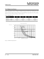
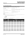
3.1.3 BEARING LOAD CAPACITY
Radial load capacity, shown in Figure 7 to Figure 10, are for a B10 life of 20,000 hours. The
load is applied at shaft extension midpoint. Curves are based on minor axial shaft loads. Consult
factory for other loading conditions. Maximum permissible axial and radial forces for brushless
MOOG servomotors during installation refer to Table 7.
Table 7: Installation Loads
Motor size
Gxx2
Gxx3
Gxx4
G4x5
Axial force
note ➼
150N
150N
300N
400N
Radial force
note ➼
500N
500N
1000N
1600N
note ➼: During installation. Lower loads apply for the rotating motor, see catalog.
Motor Series Gxx2
Speed [rpm]
12000
G4x2-2xx
10000
Gxx2-4xx
8000
Gxx2-6xx
6000
G4x2-8xx
4000
2000
0
0
100
200
300
400
500
Radial Load Capacity [N]
Figure 7: Radial Load Capacity Gxx2
Rev. c 05/01
PAGE 29 of 104
L180 User's Manual
3 SERVOMOTORS
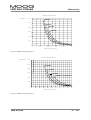
Motor Series Gxx3
Speed [rpm]
12000
G4x3-2xx
10000
Gxx3-4xx
Gxx3-6xx
8000
G4x3-8xx
6000
4000
2000
0
0
100
200
300
400
500
Radial Load Capacity [N]
Figure 8: Radial Load Capacity Gxx3
Motor Series Gxx4
Speed [rpm]
12000
10000
G4x4-2xx
8000
Gxx4-4xx
6000
Gxx4-6xx
G4x4-8xx
4000
2000
0
0
100
200
300
400
500
600
700
800
900
1000
Radial Load Capacity [N]
Figure 9: Radial Load Capacity Gxx4
PAGE 30 of 104
Rev. c 05/01
L180 User's Manual
3 SERVOMOTORS
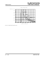
Motor Series G4x5
Speed [rpm]
8000
7000
G4x5-2xx
6000
5000
G4x5-4xx
4000
G4x5-6xx
3000
G4x5-8xx
2000
1000
0
0
200
400
600
800
1000
1200
1400
1600
Radial Load Capacity [N]
Figure 10: Radial Load Capacity G4x5
Rev. c 05/01
PAGE 31 of 104
L180 User's Manual
3 SERVOMOTORS
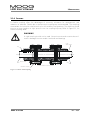
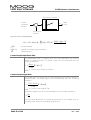
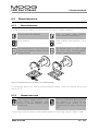
3.1.4 COUPLING
A flexible coupling offers the advantages of economy, allowance for misalignment, and
reduction of backlash. Flexible disc or bellows style couplings are recommended. The couplings
are available for both plain shaft as well as for slot and key configurations. The shaft key should
then be a close clearance or light press fit into the coupling key-way. Refer to Figure 11, for
flexible coupling detail.
WARNING
A rigid coupling should not be used. Normal runouts and eccentricities will
result in damage to motor and/or load shaft and bearings.
Load
Shaft
Key
Motor Shaft
Key
Double Flexible Coupling Detail
Flexible Coupling
Figure 11: Motor Load Coupling
PAGE 32 of 104
Rev. c 05/01
L180 User's Manual
3 SERVOMOTORS
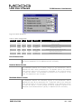
3.1.5 RUNOUT
The reduced runout provided by MOOG motors allows the attachment of various gear heads.
The precision manufacturing of the motor avoids loads caused by misalignments between
motor and gear heads.
Table 8: Shaft Runout
Diameter of the
Shaft Extension
øU [mm]
Maximum Runout Tolerance
Class R [mm]
Class N [mm]
to 10
0.015
0.030
over 10 to 18
0.018
0.035
over 18 to 30
0.021
0.040
over 30 to 50
0.025
0.050
Figure 12: Runout
Figure 13: Concentricity
Figure 14: Perpendicularity
Table 9: Flange Concentricity/Perpendicularity
Pilot Diameter of
Mounting Flange
øAK [mm]
Rev. c 05/01
Maximum Concentricity and
Perpendicularity Tolerance
Class R [mm]
Class N [mm]
to 22
0.025
0.050
over 22 to <40
0.030
0.060
40 to 100
0.040
0.080
over 100 to 230
0.050
0.100
over 230 to 450
0.063
0.125
PAGE 33 of 104
L180 User's Manual
3.2
3 SERVOMOTORS
TECHNICAL MOTOR DATA
3.2.1 STANDARDS FOR MOOG MOTORS
The brushless MOOG Global series servomotors have been designed, assembled and tested in
conformity with the following standards:
Table 10: Motor design standards
Standard
English
Certified company
International
Europe
Deutschland
USA
IEC International
Electrotechnical
Commission
EN CENELEC
Europäisches
Komitee für
Elektrotechnische
Normung
DIN / VDE Deutsche NEMA / NEC
National Electric
Industrie Norm /
Verband Deutscher Code MG.-...
Elektrotechniker
ISO 9001
EN ISO 9001
ISO 9001
EN ISO 9001
DIN ISO 9001
DIN ISO 9001
Machine guidelines (CE Machine
safety directive)
89/392/EWG,
91/368/EWG,
93/44/EWG
89/392/EWG,
91/368/EWG,
93/44/EWG
89/392/EWG,
91/368/EWG,
93/44/EWG
EMC guidelines (CE-EMC directive)
89/336/EWG,
93/68/EWG,
93/44/EWG
89/336/EWG,
93/68/EWG,
93/44/EWG
89/336/EWG,
93/68/EWG,
93/44/EWG
Low voltage guidelines (CE-Low
voltage directive)
73/23/EWG,
93/68/EWG,
93/44/EWG
73/23/EWG,
93/68/EWG,
93/44/EWG
73/23/EWG,
93/68/EWG,
93/44/EWG
ISO 9001
ISO 9001
Quality systems - model for quality
assurance in design / development,
production, installation and servicing
Standard for safety of electric motors
Safety of machinery, electrical
equipment of machines, part 1:
general requirements
PAGE 34 of 104
UL 1004 (1994)
IEC 204-1
EN 60204-1
DIN EN 60204-1
VDE 0113-1
Rev. c 05/01
L180 User's Manual
3 SERVOMOTORS
Table 11: Electrical Design Standards
Standard
International
Europe
English
IEC International
Electrotechnical
Commission
Rotating electrical machines, Rating
and performance
IEC 34-1
EN 60034-1
IEC 2/915/CDV: 1995
EN CENELEC
Europäisches Komitee
für Elektrotechnische
Normung
Deutschland
USA
DIN / VDE Deutsche
Industrie Norm /
Verband Deutscher
Elektrotechniker
NEMA / NEC National
Electric Code MG.-...
DIN EN 60034-1
VDE 0530-1
MG 1-1.65
Rotating electrical machines, Methods IEC 2G/73/FDIS
for determing losses and efficiency
and performance
EN 60034-2
DIN EN 60034-2
VDE 0530-2
IEC 34-5
Rotating electrical machines,
Classification of degrees of protection
provided by enclosure
Rotating electrical machines, Methods IEC 34-6
of cooling (IC-Code)
EN 60034-5
DIN EN 60034-5
VDE 0530-5
MG 1-1.25
MG 1-1.26
EN 60034-6
DIN EN 60034-6
VDE 0530-6
MG 1-1.25
MG 1-1.26
IEC 34-7
EN 60034-7
DIN EN 60034-7
VDE 0530-7
MG 1-4.03
Rotating electrical machines, Terminal IEC 34-8
markings and directions of rotation
EN 60034-8
DIN EN 60034-8
VDE 0530-8
MG 1-2.61
Rotating electrical machines, Noise
limits
EN 60034-9
DIN EN 60034-9
VDE 0530-9
N/A.
Rotating electrical machines,
Classification of types of construction
and mounting arrangements (IM
Code)
IEC 34-9
Insulation coordination for equipment IEC 664-1
with low-voltage systems. Part 1:
Principles, requirements and tests
VDE 0110-1
IEC 664-2
VDE 0110-2
Insulation coordinates for equipment
with low-voltage systems. Part 2:
Partial discharge tests, application
guide
Connectors and plug-and-socketdevices, for rated voltages up to 1000
V AC, up to 1200 V DC and rated
currents up to 500 A for each pole
Rev. c 05/01
DIN VDE 0627
PAGE 35 of 104
L180 User's Manual
3 SERVOMOTORS
Table 12: Motor mechanical standards
Standard
International
Europe
Deutschland
English
IEC International
Electrotechnical
Commission
EN CENELEC
Europäisches Komitee
für Elektrotechnische
Normung
DIN / VDE Deutsche
Industrie Norm /
Verband Deutscher
Elektrotechniker
Degrees of protection provided by
enclosure (IP code)
IEC 529
EN 60529
DIN EN 60529
VDE 0470-1
Cylindrical shaft ends for electrical
machines
IEC 72
ISO/R 775-1969
DIN 748-1 & 3
Mounting flanges for rotating
electrical machinery
NEMA / NEC National
Electric Code MG.-...
MG-11...
DIN 42948
Dimensions, tolerances and mounting
NEMA MG-7
Tolerances of shaft extension run-out
and of mounting flanges for rotating
electrical machinery
IEC 72
DIN 42955
Mechanical vibration, balance quality
requirements of rigid rotors,
determination of permissible residual
unbalance
ISO 1940-1
DIN ISO 1940-1
Mechanical vibration, balance quality
requirements of rigid rotors, Balance
errors
ISO 1940-2
DIN ISO 1940-2
Ball bearings, conrad type, for
electrical machines, tolerances and
radial clearance
DIN 42966
Drive type fastenings without taper
action, parallel keys, keyways, deep
pattern
ISO general purpose metric screw
ISO 724
threads. Part 1 coarse pitch threads in
diameter range 1 mm to 68 mm,
nominal sizes
DIN 6885-1
General tolerances, tolerances for
ISO 2768-1
linear and angular dimensions without
individual tolerance indications
PAGE 36 of 104
USA
DIN 13-1
EN 22768
DIN ISO 2768-1
Rev. c 05/01
L180 User's Manual
3 SERVOMOTORS
3.2.2 MOTOR PERFORMANCE DATA
Operating and ambient conditions for G4xx and G33x motor series:
Temperature for Transport
and Storage:
Degree of Protection:
-40 °C to 120°C note Ê
-25 °C to 120 °C
IP 67 with optional shaft seal or gearbox attached
(DIN VDE 0470-1, EN 60529, IEC 529)
Ambient temperature in Operation: -25 °C to 50 °C
Runout:
Class R (DIN 42955-R, IEC72) note Ê
Class N (DIN 42955-N, IEC72)
note Ë
note Ê: G4xx motor series only
note Ë: G33x motor series mating connector must be attached
Legend:
Á
Â
Motor flanged mounted onto a steel plate 300 x 300 x 12 mm with the maximum permissible temperature rise of the
winding at 100 K over a still air environment (max. 50 °C)
Speed at which the EMF of the motor is equal to the DC-bus voltage
kt =
MN
IN
conversions:
1 Nm = 8.85 lb-in
-4
1 kgcm² = 8.85x10 lb-in-sec
2
1 kg = 2.2 lb
1 kW = 1.341 hp
Table 13: Motor Performance Stall Data G400 series
Stall data
Motor type
Continuous stall torque ➲
Model
note
G4y2-2xx
Type
Mo [Nm]
G2L05
0.25
G2L10
0.50
G2L20
0.95
G2L40
1.7
G4y2-8xx
G4y3-2xx
G3L05
0.6
G3L15
1.65
G4y3-4xx
G4y3-6xx
G3L25
2.55
G3L40
3.7
G4y3-8xx
G4y4-2xx
G4L05
1.3
G4L10
2.6
G4y4-4xx
G4y4-6xx
G4L20
4.7
G4L40
8.2
G4y4-8xx
G4y4-9xx
G4L60
11
G5L10
5.8
G4y5-2xx
G4y5-4xx
G5L20
11.2
G5L30
16.6
G4y5-6xx
G4y5-8xx
G5L50
25
note: y = 1 US version; y = 2 Europe version
G4y2-4xx
G4y2-6xx
Rev. c 05/01
Continuous
stall current ➲
Peak stall
current
Peak stall torque
Mo [lb-in]
Io [Arms]
Mmax [Nm]
Mmax [lb-in]
Imax [Arms]
2.21
4.43
8.41
15.05
5.31
14.60
22.57
32.75
11.51
23.01
41.60
72.57
97.35
51.33
99.12
146.91
221.25
0.65
1.2
2.15
2.85
1.6
3.2
3.4
4.2
3.1
4.8
6.7
9.2
9.5
9.5
11
12.9
14.8
0.5
1.4
2.6
5
1.5
4.7
8.5
13
3.2
6.5
12.5
22
31
12.2
25.8
40
60
4.43
12.39
23.01
44.25
13.28
41.60
75.23
115.05
28.32
57.53
110.63
194.70
274.35
107.97
228.33
354.00
531.00
1.9
3.7
6.4
8.3
4.6
10.6
12.4
16.3
9
15
20
28
30
24
33
38
43
PAGE 37 of 104
L180 User's Manual
3 SERVOMOTORS
Table 14: Motor Performance Miscellaneous Data G400 series
Miscellaneous data
Motor type
Theoret. no
load speed ➳
Torque constant rotor inertia without brake
Mass without
brake
Poles
(polepairs)
Type
Ntheo [rpm]
kt [Nm/Arms]
kt [lb-in/Arms]
J [kgcm²]
J [lb-in-sec²]
m [kg]
m [lb]
G2L05
G2L10
G2L20
G2L40
G3L05
G3L15
G3L25
G3L40
G4L05
G4L10
G4L20
G4L40
G4L60
G5L10
G5L20
G5L30
10200
9000
7900
6300
9600
7200
4900
4100
8800
6900
5200
4200
3300
6100
3800
3000
0.37
0.42
0.46
0.60
0.40
0.53
0.75
0.90
0.42
0.54
0.70
0.89
1.16
0.61
1.02
1.29
3.27
3.72
4.07
5.31
3.54
4.69
6.64
7.97
3.72
4.78
6.20
7.88
10.27
5.40
9.03
11.42
0.09
0.13
0.22
0.41
0.16
0.39
0.62
0.97
1.05
1.55
2.60
4.70
6.80
4.60
8.00
11.50
0.00008
0.00012
0.00019
0.00036
0.00014
0.00035
0.00055
0.00086
0.00093
0.00137
0.00230
0.00416
0.00602
0.00407
0.00708
0.01018
1.0
1.2
1.5
2.3
1.4
2.0
2.6
3.5
3.0
3.6
4.7
6.9
9.1
7.7
9.9
12.1
2.20
2.64
3.30
5.06
3.08
4.40
5.72
7.70
6.60
7.92
10.34
15.18
20.02
16.94
21.78
26.62
8 (4)
8 (4)
8 (4)
8 (4)
8 (4)
8 (4)
8 (4)
8 (4)
12 (6)
12 (6)
12 (6)
12 (6)
12 (6)
12 (6)
12 (6)
12 (6)
G4y5-8xx
G5L50
2200
1.69
note: y = 1 US version; y = 2 Europe version
14.96
18.40
0.01628
16.6
36.52
12 (6)
Model
note
G4y2-2xx
G4y2-4xx
G4y2-6xx
G4y2-8xx
G4y3-2xx
G4y3-4xx
G4y3-6xx
G4y3-8xx
G4y4-2xx
G4y4-4xx
G4y4-6xx
G4y4-8xx
G4y4-9xx
G4y5-2xx
G4y5-4xx
G4y5-6xx
Table 15: Motor Performance Stall Data G300 series
Stall data
Motor type
Continuous stall torque ➲
Model
Type
G332-4xx
G332-6xx
Continuous stall
current ➲
Peak stall torque
Mmax [Nm]
Peak stall current
Mo [Nm]
Mo [lb-in]
Io [Arms]
Mmax [lb-in]
Imax [Arms]
L2L10
0.5
4.43
1.15
L2L20
0.95
8.41
2
1
8.85
2.3
1.9
16.82
G333-4xx
L3L15
1.6
14.16
3
4
3.2
28.32
6
G333-6xx
L3L25
2.6
23.01
3.3
G334-4xx
5.2
46.02
6.6
L4L10
2.5
22.13
4.5
4.7
41.60
9
G334-6xx
L4L20
5
44.25
7
9.4
83.19
14
Table 16: Motor Performance Miscellaneous Data G300 series
Miscellaneous data
Motor type
Theoret. no
load speed ➳
Torque constant ➴
rotor inertia without brake
Mass without
brake
Poles
(polepairs)
Model
Type
Ntheo [rpm]
kt [Nm/Arms]
kt [lb-in/Arms]
J [kgcm²]
J [lb-in-sec²]
m [kg]
m [lb]
G332-4xx
L2L10
9000
0.44
3.89
0.13
0.00012
1.2
2.64
8 (4)
G332-6xx
L2L20
7900
0.49
4.34
0.22
0.00019
1.5
3.30
8 (4)
G333-4xx
L3L15
7200
0.55
4.87
0.37
0.00033
2
4.40
8 (4)
G333-6xx
L3L25
4900
0.8
7.08
0.59
0.00052
2.6
5.72
8 (4)
G334-4xx
L4L10
6900
0.58
5.13
1.5
0.00133
3.6
7.92
12 (6)
G334-6xx
L4L20
5200
0.76
6.73
2.5
0.00221
4.7
10.34
12 (6)
PAGE 38 of 104
Rev. c 05/01
L180 User's Manual
3 SERVOMOTORS
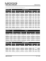
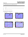
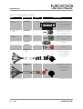
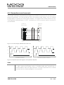
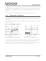
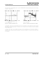
3.2.3 TORQUE SPEED CHARACTERISTIC G400 SERIES MOTORS
Legend:
torque limit for continuous operation (winding 100 K above ambient, with motor mounted to 300mm x 300mm x 12mm
steel plate)
peak torque at approx. three times continuous stall current with L180 controller (higher torque at higher current levels
possible)
kt-line gives torque at current level (top axis)
Drive System L180 - Servomotor G4x2
G4x2-2xx (G2L05)
0.0
0.5
1.0
G4x2-4xx (G2L10)
Current (Arms)
2.0
2.5
1.5
3.0
1.0
0
8.85
0.9
1
2
3
4
5
Current (Arms)
7
8
9
6
2.4
10
20.0
7.96
2.2
7.08
2.0
16.7
1.8
15.0
1.6
13.3
1.4
11.7
1.2
10.0
1.0
8.3
18.3
3
0.8
3
5.31
0.5
4.42
0.4
3.54
0.3
2.65
2
0.2
1
0.1
0.0
0
0.8
6.7
2
0.6
5.0
1
1.77
0.4
3.3
0.88
0.2
1.7
0.0
0.00
1000 2000 3000 4000 5000 6000 7000 8000 9000 100001100012000
0
1000
2000
3000
4000
Figure 15: Torque-Speed Char. G2L05
G4x2-6xx (G2L20)
1
2
3
4
5
6000
7000
8000
0.0
9000 10000
6
Figure 16: Torque-Speed Char. G2L10
Current (Arms)
7
8
9
G4x2-8xx (G2L40)
10
0
5.0
41.7
4.5
37.5
4.0
33.3
2
4
6
8
10
Current (Arms)
12
14
8
16
66.7
7
58.3
3
3
3.5
6
50.0
5
41.7
25.0
2.5
20.8
2.0
16.7
1.5
4.2
0.0
2000
3000
4000
5000
6000
7000
speed (rpm)
Figure 17: Torque-Speed Char. G2L20
Rev. c 05/01
3
25.0
16.7
1
8.3
0.5
1000
33.3
2
2
1
0
4
12.5
2
1.0
Torque (lb-in)
3.0
Torque (Nm)
29.2
Torque (lb-in)
Torque (Nm)
5000
speed (rpm)
speed (rpm)
0
Torque (lb-in)
0.6
Torque (Nm)
6.19
Torque (lb-in)
Torque (Nm)
0.7
8000
0.0
9000 10000
1
8.3
0
0
1000
2000
3000
4000
5000
6000
7000
0.0
8000
speed (rpm)
Figure 18: Torque-Speed Char. G2L40
PAGE 39 of 104
L180 User's Manual
3 SERVOMOTORS
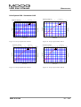
Drive System L180 - Servomotor G4x3
G4x3-2xx (G3L05)
0
1
2
3
4
5
G4x3-4xx (G3L15)
Current (Arms)
7
8
9
6
10
2.4
3
6
9
3
15
Current (Arms)
18
21
66.7
1.6
13.3
1.4
11.7
1.2
10.0
1.0
8.3
2
6.7
Torque (Nm)
15.0
0.2
1.7
0.0
0
6
50.0
5
41.7
4
33.3
3
25.0
1
2
5.0
3.3
58.3
2
1
0.4
7
Torque (lb-in)
1.8
Torque (lb-in)
16.7
0.8
8.3
0
0.0
1000 2000 3000 4000 5000 6000 7000 8000 9000 10000 11000
0
1000
2000
3000
G4x3-6xx (G3L25)
10
4000
5000
6000
7000
0.0
8000
speed (rpm)
Figure 19: Torque-Speed Char. G3L05
5
16.7
1
speed (rpm)
0
24
3
18.3
2.0
0.6
Figure 20: Torque-Speed Char. G3L15
Current (Arms)
20
25
15
13
G4x3-8xx (G3L40)
30
0
115.0
3
12
11
106.2
5
10
15
20
25
30
Current (Arms)
35
40
45
50
20
167
18
150
16
133
97.3
79.6
14
117
8
70.8
12
100
7
61.9
6
53.1
5
44.2
2
4
1
3
35.4
26.5
2
17.7
1
8.8
0
0.0
500 1000 1500 2000 2500 3000 3500 4000 4500 5000 5500 6000
0
speed (rpm)
Figure 21: Torque-Speed Char. G3L25
PAGE 40 of 104
Torque (Nm)
88.5
9
10
83
2
8
67
6
Torque (lb-in)
10
Torque (lb-in)
Torque (Nm)
12
8
20.0
2.2
Torque (Nm)
0
11
50
1
4
33
2
17
0
0
500
1000
1500
2000
2500
3000
3500
4000
4500
0
5000
speed (rpm)
Figure 22: Torque-Speed Char. G3L40
Rev. c 05/01
L180 User's Manual
3 SERVOMOTORS
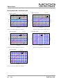
Drive System L180 - Servomotor G4x4
G4x4-2xx (G4L05)
0
2
4
6
8
10
12
14
16
Current (Arms)
18
20
22
G4x4-4xx (G4L10)
0
24
5.0
42
4.5
38
5
10
15
20
Current (Arms)
25
83
9
2.5
21
2.0
17
2
Torque (Nm)
25
8
67
7
58
6
50
5
13
3
8
2
0.5
4
1
0.0
0
500 1000 1500 2000 2500 3000 3500 4000 4500 5000 5500 6000
0
1.5
1
1.0
0
42
2
4
33
25
1
0
0
500 1000 1500 2000 2500 3000 3500 4000 4500 5000 5500 6000
speed (rpm)
Figure 23: Torque-Speed Char. G4L05
G4x4-6xx (G4L20)
5
10
15
20
25
30
35
Figure 24: Torque-Speed Char. G4L10
Current (Arms)
45
50
55
40
0
167
16
133
14
117
20
30
83
8
67
2
292
30
250
25
208
20
167
2
15
125
0
speed (rpm)
30
40
500
1000
1500
2000
2500
3000
3500
4000
4500
0
5000
speed (rpm)
Figure 25: Torque-Speed Char. G4L20
20
42
0
0
500 1000 1500 2000 2500 3000 3500 4000 4500 5000 5500 6000
G4x4-9xx (G4L60)
83
1
5
17
10
100
333
10
2
0
Current (Arms)
70
80
90
60
35
33
0
50
50
1
0
40
Torque (lb-in)
100
10
Torque (lb-in)
12
Torque (Nm)
150
4
Current (Arms)
50
60
Figure 26: Torque-Speed Char. G4L40
70
60
80
531
3
55
487
50
442
45
398
40
354
35
310
30
265
25
221
20
177
2
15
10
Torque (lb-in)
Torque (Nm)
10
40
3
3
18
Torque (Nm)
G4x4-8xx (G4L40)
60
20
6
17
8
speed (rpm)
0
Torque (lb-in)
29
3.0
Torque (lb-in)
Torque (Nm)
33
3.5
75
3
3
4.0
30
10
133
88
1
5
44
0
0
500
1000
1500
2000
2500
3000
3500
0
4000
speed (rpm)
Figure 27: Torque-Speed Char. G4L60
Rev. c 05/01
PAGE 41 of 104
L180 User's Manual
3 SERVOMOTORS
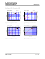
Drive System L180 - Servomotor G4x5
G4x5-2xx (G5L10)
0
10
20
30
Current (Arms)
50
60
40
G4x5-4xx (G5L20)
0
70
20
10
20
30
40
Current (Arms)
60
70
80
50
90
35
177
310
3
142
14
124
12
106
10
88
8
71
2
1
6
53
4
35
2
18
0
0
1000
2000
3000
4000
5000
6000
30
265
25
221
20
177
2
15
133
1
10
88
5
44
0
0
7000
0
500
1000
1500
Figure 28: Torque-Speed Char. G5L10
G4x5-6xx (G5L30)
10
20
30
40
3000
3500
4000
0
4500
50
Figure 29: Torque-Speed Char. G5L20
Current (Arms)
60
70
Current (Arm s)
G4x5-8xx (G5L50)
0
80
10
20
30
40
50
60
70
80
90
100 110 120
100
885
531
55
487
90
50
442
80
45
398
70
619
40
354
60
531
30
265
2
25
221
20
177
796
3
708
50
442
2
40
265
1
1
15
354
30
133
10
88
5
44
20
177
10
88
0
0
0
500
1000
1500
2000
2500
3000
speed (rpm)
Figure 30: Torque-Speed Char. G5L30
PAGE 42 of 104
Torque (lb-in)
310
Torque (lb-in)
35
Torque (Nm)
60
3
Torque (Nm)
2500
speed (rpm)
speed (rpm)
0
2000
Torque (lb-in)
16
Torque (Nm)
159
3
Torque (lb-in)
Torque (Nm)
18
3500
0
4000
0
0
200 400 600 800 1000 1200 1400 1600 1800 2000 2200 2400
speed (rpm)
Figure 31: Torque-Speed Char. G5L50
Rev. c 05/01
L180 User's Manual
3 SERVOMOTORS
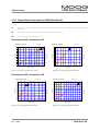
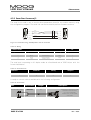
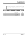
3.2.4 TORQUE-SPEED-CHARACTERISTICS G300 SERIES MOTORS
Legend:
torque limit for continuous operation (winding 100 K above ambient, with motor mounted to 300mm x 300mm x 12mm
steel plate)
peak torque at approx. two times continuous stall current with L180 controller
kt-line gives torque at current level (top axis)
Drive System L180 - Servomotor G332
G332-4xx (L2L10)
0
1
2
G332-6xx (L2L20)
Current (Arms)
4
3
5
2.0
1.2
1.0
1.0
0.8
0.8
2
4
5
Current (Arms)
7
8
9
6
10
26,5
2,5
22,1
2,0
17,7
1,5
13,3
2
1,0
8,8
0.6
1
0.4
0.4
0.2
0.2
0.0
2000
Torque (Nm)
1.4
1.2
1000
3
3000
4000
5000
6000
7000
8000
Torque (lb-in)
1.4
Torque (lb-in)
1.6
0
2
1.8
1.6
0.6
1
3
3
1.8
Torque (Nm)
0
3,0
2.0
1
0,5
4,4
0,0
0.0
9000 10000
0
1000
2000
3000
speed (rpm)
4000
5000
6000
7000
8000
0,0
9000 10000
speed (rpm)
Figure 32: Torque-Speed Char. L2L10
Figure 33: Torque-Speed Char. L2L20
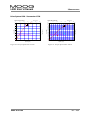
Drive System L180 - Servomotor G333
G333-4xx (L3L15)
0
3
6
9
12
15
Current (Arms)
18
21
5,0
0
1
2
3
4
5
6
Current (Arms)
8
9
10
7
11
12
9
44,2
79.6
3
3
4,5
70.8
35,4
7
61.9
3,5
31,0
6
53.1
3,0
26,5
5
44.2
2
2,5
22,1
2,0
17,7
1,5
Torque (Nm)
8
4,0
4
1,0
8,8
0,5
4,4
0,0
0,0
8000
0
2000
3000
4000
5000
6000
speed (rpm)
Figure 34: Torque-Speed Char. L3L15
Rev. c 05/01
26.5
7000
1
2
1
1000
35.4
2
3
13,3
1
0
Torque (lb-in)
39,8
Torque (lb-in)
Torque (Nm)
G333-6xx (L3L25)
24
17.7
8.8
0
0.0
500 1000 1500 2000 2500 3000 3500 4000 4500 5000 5500 6000
speed (rpm)
Figure 35: Torque-Speed Char. L3L25
PAGE 43 of 104
L180 User's Manual
3 SERVOMOTORS
Drive System L180 - Servomotor G334
G334-4xx (L4L10)
0
5
10
15
20
Current (Arms)
25
7
G334-6xx (L4L20)
30
0
6
53
35
2
3
27
18
1
1
9
0
1000
2000
3000
4000
speed (rpm)
Figure 36: Torque-Speed Char. L4L10
PAGE 44 of 104
15
20
5000
0
6000
Current (Arms)
25
30
124
3
115
12
106
11
97
10
88
9
80
8
71
7
62
6
2
5
53
44
4
35
1
3
27
2
18
1
9
0
0
Torque (lb-in)
4
Torque (Nm)
44
Torque (lb-in)
Torque (Nm)
5
0
10
13
3
2
5
14
62
0
500 1000 1500 2000 2500 3000 3500 4000 4500 5000 5500 6000
speed (rpm)
Figure 37: Torque-Speed Char. L4L20
Rev. c 05/01
L180 User's Manual
3 SERVOMOTORS
3.2.5 MOTOR BRAKE DATA
The following is the specification data for the G4xx motor brakes. Options are specified in the
motor box-car drawing. A regulated DC power supply is recommended.
Table 17: G4xx Motor Brake Data
G4x2
Series
Brake
Parameter
Rated Braking
Holding Torque
Inertia
G4x3 Series
Brakes
G4x4 Series
Brakes
G4x5 Series
Brakes
Option 1
Option 2
Option 1
Option 2
Option 1
Option 2
0.9
1.5
3.0
6.0
15.0
15.0
25.0
[lb-in]
7.97
13.28
26.55
53.10
132.75
132.75
221.25
[kg cm2]
0.02
0.07
0.18
0.54
1.00
1.00
3.6
[Nm]
[lb-in-sec²]
0.00002
0.00006
0.00016
0.00048
0.00089
0.00089
0.00319
Rated Voltage
[V]
24 +/-15%
24 +/-15%
24 +/-15%
24 +/-15%
24 +/-15%
24 +/-15%
24 +/-15%
Power Consumption
at 20 °C (68 F)
[W]
11
11
10
13
19
19
24
Time to Disengage,
t1
[ms]
20
20
20
30
50
50
80
Time to Engage, t2
[ms]
15
15
15
25
35
35
40
Current at 24 VDC
to release
[A]
0.46
0.46
0.42
0.54
0.79
0.79
1.0
Figure 38:Current/time and torque/time diagrams
Rev. c 05/01
PAGE 45 of 104
L180 User's Manual
PAGE 46 of 104
3 SERVOMOTORS
Rev. c 05/01
4 INSTALLATION
4
L180 User's Manual
INSTALLATION
This chapter on installation refers to L180 servo drives series. The wiring of the L180 servo drive
must be carried out according to the schematics in these instructions. Local wiring regulation
must be observed. Special attention should be paid with respect to wiring rules regarding
ground, earth and neutral. The earth wire to the drive, motor and housing must be as short as
possible and connected to a common earth point.
4.1
WIRING
The following is a general reminder of the cable requirements for the L180 servo drive series
and related equipment.
Cabling and component wiring is critical in obtaining successful operation of the system. Pay
close attention to specified wiring practice, cabling information, earth and shielding
requirements. Improper wiring can result in electrical noise generation and unstable motor
performance.
Size wire in accordance with standard wiring practice and local codes for amperage and wire
length.
Particular care should be taken when layout of a cabinet is designed. Efforts to separate routing
of signal and power wires should be taken. The following guidelines should be taken into
account:
•
Separate signal and power cable for low noise emission
•
Minimize of radiated interference by using of shielded signal cables
•
Signal cable should cross power cable at an angle of 90°. This reduces field coupling which
causes noise.
All electrical supply wires and cables to this equipment must be installed in conduits (cable
routings) which are smooth and free from sharp edges.
Rev. c 05/01
PAGE 47 of 104
L180 User's Manual
4.2
4 INSTALLATION
CONNECTOR OVERVIEW
J1 RESOLVER
Terminal for resolver
cable
J3 AXIS SIGNALS
Analog Input
Digital Input/Output
Status Relay Contact
J2 SERIAL PORT
RS 232 Interface
J4 ESM OUT
Differential encoder
output signals from
RS422 line driver, A, A,
B, B, Z, Z
J5 LOGIC POWER
24 VDC Power Supply
Input,
± 15 VDC Output
STATUS
seven segment display
for status information
TB1 power connector
Terminal for main lines
and motor cable
PROTECTIVE EARTH
Screw terminal for PE
and grounding
(screw not visible)
REGEN ACTIVE
red LED, lights up if
motor regenerates
energy to drive
Figure 39: Wiring Overview
WARNING
The PE terminal of the drive must be permanently connected to the earth
potential. The cross-section of the protective conductor must be at least
4mm² (AWG 10) copper (Cu).
PAGE 48 of 104
Rev. c 05/01
L180 User's Manual
4 INSTALLATION
4.2.1 MOTOR AND POWER CONNECTOR TB1
The servo drive unit can be operated with either a single-phase or three-phase AC voltage.
Table 18: Main line voltage
Mains frequency
Supply Voltage
Unit
Minimum
Regular
Maximum
Hz
45
50/60
65
VAC
184
230
253
WARNING
A three phase automatic circuit breaker must be used for three phase
operation in order to ensure that all phases are tripped at the same time in
the event of a fault! The wire protection must be taken into account. This
depends on the cross-section of the main line wires. Please refer to your
local regulations for detailed information.
Single phase operation
TB1:L1
TB1:L2
In single phase operation, the voltage between live and neutral is 230 VAC.
The phase line should be connected to TB1:L1 and the neutral line to
TB1:L2. The protective earth conductor must also be connected to the earth
stud on the drive.
Three phase operation
TB1:L1
TB1:L2
TB1:L3
The nominal voltage between the servo drive unit terminals must be equal
to 230 VAC. The phase-to-phase voltage of a normal 3-phase 400 VAC
(440 VAC) mains supply must be stepped down to 230 VAC by means of an
auto or isolation transformer connected to terminal TB1. The protective
earth conductor must be connected to the earth stud on the drive.
Transformer
The selection of the transformer size depends on the ambient conditions,
duty cycle and power requirements of the application. Two or more drives
can be connected to one transformer. The transformer must deliver the
maximum current. In any case of uncertainty do not hesitate to contact your
local application engineer.
Additional Parts for the drive system
Additional fuses for transformer and wiring protection have to be installed
according to the local regulations. The transformer protection should be
clarified with the transformer supplier. Contactors are to be used where
necessary. Examples of contactor use include: emergency stop and on/off
circuits. A main power switch may also be necessary because of local
regulations.
Rev. c 05/01
PAGE 49 of 104
L180 User's Manual
4 INSTALLATION
E
E’
L1’
LINE FILTER
SCHAFFNER
FN 258
L2’
L2
L2
L3
L3
L3’
L1
L1
L1
3~ 230 VAC
50/60 Hz
L2
3~ 400 VAC/3~440 VAC
50/60Hz
L3
SHIELD
S
W
WWW
black
1
V
VV
black
4
V
U
U
black
2
U
white
5
+
black
6
-
W
G4x2 G4x5
G4x3
G4x4
yellow / green
ELECTROMAGNETIC
BRAKE
NORMALLY CLOSED
PROTECTIVE EARTH
MOOG MOTOR
SEPARATE
CONTACTOR
/
RELAY
24VDC
POWER
SUPPLY
+
Customer Supplied
-
Figure 40: TB1 Wiring
Brake
The brake is released with 24 VDC. This voltage must be provided and
controlled by an auxiliary power supply. The L180 servo drive does not
support any brake control. The brake is designed for static holding
applications where the shaft is held during disabling of the drive. If the brake
is used for dynamic braking several times, it will become worn and the
braking effect will deteriorate. The brake is not designed to replace safety
functions.
Customer supplied parts
MOOG can not accept any warranty of customer supplied components even
when they are necessary for the operating system.
Maximum Cable length
The maximum cable length from servo drive to motor is 100 m (328 ft).
PAGE 50 of 104
Rev. c 05/01
L180 User's Manual
4 INSTALLATION
WARNING
The motor must be wired and tested consistent to this manual.
• Power cable
An incorrect phase sequence can cause the motor to accelerate in an
uncontrolled manner upon enabling the drive.
Sufficient line filter for a single axis application is shown in the table below.
Table 19: EMC Filter
line filters
L180-310A
L180-410A
L180-510A
FN 258-7
FN 258-16
FN 258-16
CE-COMPLIANCE
EMC-FILTER
A line filter must be installed between the drive and the main transformer
otherwise CE conformity is not guaranteed. The table above shows
appropriate line filters manufactured by Schaffner, Switzerland. All EMC
measurements were done with these filters. Only one line filter need be
used if more than one drive is connected to the transformer. The current of
the filter has to meet the overall current of the drive arrangement.
Customer
Supplied
E
E’
L1’
L2’
LINE FILTER
SCHAFFNER
FN 258
L1
L1
L2
L2
L3
L3’
L3
U
W
V
L3
S
L1
U
V
W
L3
S
L1
L2
3~ 400 VAC/3~440 VAC
50/60Hz
L2
3~ 230 VAC
50/60 Hz
Additional Drives
Figure 41: Multi Axis Wiring
Rev. c 05/01
PAGE 51 of 104
L180 User's Manual
4.2.1.1
4 INSTALLATION
TB1 POWER CONNECTOR PINOUT
Table 20: TB1 power connector pinout
MOOG motors pin number
TB1 power connector
pin number
pin name
L1,L2,L3
L1,L2,L3
S
Shield PE
main line terminal
3~ 230 VAC
motor cable shield
W
W
motor phase W (C)
4.2.1.2
function
pin type
Gxx2, Gxx3,
Gxx4
G4x5
power input
-
-
PE potential
shield
shield
power output
1
W
V
V
motor phase V (B)
power output
4
V
U
U
motor phase U (A)
power output
2
U
ACCESSORY POWER PART
General Cable Specification
Designed for use in cable tracks, as tailing cable and oil environment,
temperature range: -50 °C to 90 °C continuous operation (-58 °F to 194 °F),
150 °C (302 °F) maximum temperature, bending cycles > 1 million, bend
radius for cable chain > 12 x outer diameter
PAGE 52 of 104
Rev. c 05/01
L180 User's Manual
4 INSTALLATION
Table 21: Accessory parts power connector
Description
Part Number
Motor
Drive mating power
connector
C08474-001
all drives
Raw Power Cable
note ➼
B47890-001
Gxx2, Gxx3, Gxx4
Raw Power Cable
note ➼
B47903-001
G4x5
Motor Power Connector
C08365-001
Gxx2, Gxx3, Gxx4
Motor Power Connector
B47736-001
G4x5
Power connector for customer
configuration
C08336-001-xxx
note ➽
Gxx2, Gxx3, Gxx4
Prefabricated motor cable with
mating motor connector and
ferrule ended leads,
4 x 1.5 mm² power leads,
2 x 1 mm² brake leads,
outer shield
L1
L2
L3
S
W
V
U
Part
Motor Power Cable
Shielded cable for customer
configuration, 4 x 1.5 mm² power
leads, 2 x 1 mm² brake leads,
outer shield
Shielded cable for customer
configuration, 4 x 2.5 mm² power
leads, 2 x 1 mm² brake leads,
outer shield
Power connector for customer
configuration
VIEW
Motor Power Cable
B47915-001-xxx
note ➽
G4x5
VIEW
note ➼: consult local sales office
Rev. c 05/01
Mating power connector for all
drives. Supplied with each drive,
spare part. Type Weidmueller STVS
7 SB, cross-sectional area
0.5 - 4 mm², 20 - 12 AWG.
Prefabricated motor cable with
mating motor connector and
ferrule ended leads,
4 x 2.5 mm² power leads,
2 x 1 mm² brake leads,
outer shield
note ➽: xxx length in meter
PAGE 53 of 104
L180 User's Manual
4 INSTALLATION
4.2.2 RESOLVER CONNECTOR J1
Correct wiring of the resolver is necessary for reliable operation of the L180 servo drive. Noncompliance with the instructions in this manual will cause a deterioration of specified
performance.
Standard
colors
Alternative
colors
green
yellow
grey
pink
black / green
green
8
4
3
7
9
Shield 5
Connector
housing 2
6
blue
red
black / red
red
black / white
white
white
brown
black / blue
blue
1
2
3
4
7
8 Shield
Connector
5 housing
6
MOTOR SIDE
DSUB9 MALE
DRIVE SIDE
Figure 42: Resolver wiring, DSUB 9 male cable to J1
The overall shield must be connected to both the motor and the servo drive. The proper
bonding of shielded cables is imperative for minimizing noise emissions and increasing immunity
levels of the drive system. It should be noted that the contact from the overall shield to servo
drive and motor must be made by using as much contact area as possible. It is recommended to
follow the convention (signal / conductor color) used in this manual.
Table 22: J1 Resolver connector pinout
J1 RESOLVER
pin number
MOOG motors
pin name
1
function
pin type
do not connect
pin number
not connected
2
TH.MOT1 NTC
NTC motor thermistor
input
5
3
SIN S2
resolver feedback sine
input
3
4
COS S3
resolver feedback cosine
input
2
5
REFOUT R2
resolver reference, negative
output
8
6
TH.MOT2 NTC
NTC motor thermistor
input
6
7
SIN2V5 S4
resolver feedback sine
input
4
8
COS2V5 S1
resolver feedback cosine
input
1
9
REFOUT R1
resolver reference, positive
output
7
PAGE 54 of 104
Rev. c 05/01
L180 User's Manual
4 INSTALLATION
WARNING
The motor must be wired and tested consistent to this manual.
• Signal cable
Incorrect connection of the leads can cause the motor to accelerate in an
uncontrolled manner when the drive is enabled. Any broken wire of the
NTC connection means a loss of the thermal motor protection. The drive
monitors the NTC resistor value and determines if it is above or below 4.2
kΩ. The resistor value is interpreted as motor temperature below or
above 155°C (insulation class F). A secure connection must be ensured.
4.2.2.1
ACCESSORY RESOLVER PARTS
Table 23: Resolver parts
Part
Description
Part Number
Motor
Raw signal cable
note ➼
B47885-001
all motors
Motor mating signal
connector
C08309-001
all motors
Signal connector for customer
configuration
C08335-003-xxx
note ➽
all motors
Prefabricated signal cable with
mating drive and motor connectors.
Mating connector in angular style
with orientation to the top of the
drive, 4 x 2 x 0.25 mm² leads,
stranded wires,
twisted paired, outer shield
Signal Cable
7.0 mm
note ➼: consult local sales office
Shielded cable for customer
configuration, 4 x 2 x 0.25 mm²
leads,stranded wires,
twisted paired, outer shield
note ➽: xxx length in meter
General Cable Specification
Designed for use in cable tracks, as tailing cable and oil environment,
temperature range: -50 °C to 90 °C continuous operation (-58 °F to 194 °F),
150 °C (302 °F) maximum temperature, bending cycles > 1 million, bend
radius for cable chain > 12 x outer diameter
Maximum Cable length
The maximum cable length from servo drive to motor is 100 m (328 ft).
Rev. c 05/01
PAGE 55 of 104
L180 User's Manual
4 INSTALLATION
4.2.3 SERIAL PORT CONNECTOR J2
The serial link is used to set or monitor drive parameters stored in non-volatile memory using
the configuration program. The serial link can also be used to perform firmware revisions.
RXD 2
TXD 3
GND 5
DSUB9
FEMALE
white
2 RXD
brown
3 TXD
yellow
5 GND
Shield
Connector
housing
Shield
Connector
housing
DSUB9
FEMALE
Figure 43: Serial link wiring, DSUB9 female cable to J2 and PC
Table 24: Wiring
J2 SERIAL PORT
PC
pin number
pin name
function
1,4,6,7,8,9
pin type
pin number
do not connect
2
RX232
receive data line
input
3
3
TX232
transmit data line
output
2
5
GND
common ground
5
The serial port is operating in full duplex mode at a fixed baud rate of 9600 bit/sec. with the
format listed below.
Table 25: Serial Protocol
Start bit
Data bit
Parity
Stop bit
8
no
1
1
A ready-to-connect cable is available with the following configuration.
Table 26: Serial Cable
Part
Serial Port RS232 cable
PAGE 56 of 104
Part Number
Length
C08475-001
5m
Description
Prefabricated Commisioning cable
between PC and each drive,
4 x 2 x 0.25 mm² leads,
stranded wires, twisted paired,
outer shield
Rev. c 05/01
L180 User's Manual
4 INSTALLATION
4.2.4
AXIS SIGNALS CONNECTOR J3
± 10 VDC
variable
Voltage
Source
ANALOG IN-
2
ANALOG IN+
3
MINIMUM WIRING
1
14
GND
GND24V
15
ENABLE24V
Enable Switch
16
4
17
GND
24VDC
Power
Supply
5
AUTO/MANUAL
Switch
18
6
19
END-SW1
20
END-SW2
AUTO/MANUAL 7
24VDC
Power
Supply
ALARM
+
-
8
21
9
22
ALARM COM
Input
10
Enable Switch
Host
computer
/
PLC
ENABLE COM
12
GND
13
23
11
24
GND
25
13
GND
GND
Standard Alternative
Endswitch Endswitch
Standard Alternative
Endswitch Endswitch
DSUB25 MALE
Figure 44: J3 Axis Signals Wiring, DSUB25 male cable to J3
Table 27: J3 Pin out
J3 Axis Signals
pin
number
4, 6, 9, 16,
17, 18, 21,
22, 23, 24
1, 5, 11, 13,
25
pin name
function
GND
general purpose ground for digital input,
output and reference for analog in
ANALOG IN -
negative differential input command
3
ANALOG IN +
positive differential input command
AUTO/
MANUAL
ALARM,
ALARM COM
digital input for current limitation to the
adjusted value
potetial free n. o. contact for the
adjustable alarm, ready relay
passive enable, connecting to ground via
any contact enables the drive.
8, 10
pin type
do not connect
2
7
specification
ground
max. differential input voltage +- 10 VDC,
differential input impedance 8kτ
max. differential input voltage +- 10 VDC,
differential input impedance 8kτ
analog input
analog input
internal pull-up resistor 4.7 kτ to 5 VDC
digital input
24 VDC, 0.5 A, 10VA
relay contact
internal pull-up resistor 4.7 kτ=to 5 VDC
digital input
12
ENABLE COM
14
GND 24V
ground of the active optocoupled ENABLE
potential free, max. 50 VDC to GND
external
ground
15
ENABLE 24V
active optocoupled ENABLE
max. input voltage 30 VDC to GND 24V
potential free, max. 50 VDC to GND
active level 20 - 30 VDC / 5kΩ
input
19
END-SW1
internal pull-up resistor 4.7 kτ=to 5 VDC
digital input
20
END-SW2
internal pull-up resistor 4.7 kτ to 5 VDC
digital input
Rev. c 05/01
limit switch input affecting the positive
analog command
limit switch input affecting the negative
analog command
PAGE 57 of 104
L180 User's Manual
4 INSTALLATION
ANALOG IN
J3:2 ANALOG IN J3:3 ANALOG IN +
This function has to be wired. Common mode voltage range (CMVR) +/-10V
if common on ANALOG IN. The scaling of the analog input is programmable
in speed mode.
Drives with firmware revision A1 (firmware C08500-001) are fixed in current
mode to the maximum drive current, e.g. 10VDC input on a L180-310A
drive corresponds with 10 Arms.
VIN = ±
I max,motor
I max,drive
⋅10VDC
If a motor is used with less than the maximum drive current the available
voltage range of the analog input is reduced, e.g. 15 Arms maximum motor
current leads to an analog input voltage range of ± 7.5 V at a drive with 20
Arms maximum drive current. The drive is not delivering more current than
programmed.
Drives with firmware revision A2 (firmware C08500-002) are scaled to the
maximum motor current (parameter 3) on the analog input.
A positive command leads to a clockwise rotation when viewed from the
shaft side. A negative command leads to a counter-clockwise rotation when
viewed from the shaft side( Definition of sense of rotation see Figure 78).
AUTO/MANUAL
J3:7 AUTO/MANUAL
GND
This function is programmable in the L180GUI and need not be wired. The
AUTO/MANUAL mode selection with pin 7 is a protection designed for the
commissioning phase of the drive. An open contact selects the MANUAL
mode.
Drives with firmware revision A1 (firmware C08500-001) limits the current of
the drive to the preconfigured value, therefore only limited motor torque is
available. This feature offers no speed limitation.
Drives with firmware revision A2 (firmware C08500-002) limits the current
and speed of the drive to the preconfigured value, therefore only limited
motor torque and speed is available.
A closed contact to ground selects the AUTO mode with full drive capability.
The MANUAL limit values are programmable and could also be set to the
maximum motor current and speed, thus the AUTO/MANUAL mode selection
is superfluous.
Monitoring Relay
J3:8 ALARM
J3:10 ALARM COM
PAGE 58 of 104
This function is programmable in the L180GUI. The monitoring relay can be
used to supply drive status information to other devices such as a host
computer, PLC, etc.
Rev. c 05/01
L180 User's Manual
4 INSTALLATION
Enable Options
J3:12 ENABLE COM
GND
J3:14 GND 24V
J3:15 ENABLE 24V
One of the following two cases must be used. The drive can be enabled
either with a 24VDC differential between pins 14 and 15 (optical isolated) or
with a relay contact (switch) on pin 12 to ground (GND). Both options are
connected in OR function, if one of them is activated the drive is enabled.
The power stage is enabled within two sample periods (< 300 µs) after
enable transition.
Endswitch
J3:19 END-SW1
J3:20 END-SW2
GND
This function is programmable in the L180GU. Each combination (n.c., n.o.)
of the Endswitch contacts could be used as shown in Figure 44 J3 Axis
Signals Wiring. Close end switch to GND to inhibit or allow motor movement
(dependent upon configuration).
Minimum Wiring
Only the ANALOG IN input and one of the Enable options have to be
connected to operate the drive, other functions are programmable in the
L180 GUI and can be set to values which make wiring unnecessary.
Ground
All pin ground’s are connected together with protective earth. The grounds
in Figure 44 J3 axis wiring are interchangeable and connected only to
simplify the drawing layout.
Galvanic isolation
The power module itself is isolated from the control circuits.
Rev. c 05/01
PAGE 59 of 104
L180 User's Manual
4 INSTALLATION
4.2.5 ENCODER SIMULATION CONNECTOR J4
The Encoder simulation offers differential signals from a RS422 line driver which can be used for
positioning purposes. The lines are driven with the internal power supply, thus no external
voltage supply is necessary for the Encoder simulation. The figure below shows sufficient wiring.
These signals are always present. A 120 Ω= termination on the line receiver (motion controller) is
recommended.
J4 ESM OUT
DSUB15 MALE
1
9
2
10
3
11
4
12
5
13
6
14
7
15
8
Positioning
Controller
/
PLC
GND
A
GND
B
A
B
B
B
GND
Z
Z
Z
Z
A
A
Shield
Connector
housing
Shield
Connector
housing
Figure 45: Encoder Output, DSUB15 male cable to J4
A
A
B
B
Z
Z
clockwise rotation
t
counterclockwise rotation
t
Figure 46: Definition of Encoder Signals, viewed from the shaft side
Cable
The maximum cable length is 20m (66 ft). The exact cable length is dependent
on cable routing and system noise. A shielded cable with twisted pair is
recommended to lower the signal distortion. Twisting Inverted and non inverted
lines improves the robustness against noise sensitivity.
PAGE 60 of 104
Rev. c 05/01
L180 User's Manual
4 INSTALLATION
Encoder Resolution
The resolution of the Encoder signals is programmable up to 2048 pulses per
revolution (ppr). An extrapolated mode is used between 1025ppr and 2048ppr.
The resolution up to 2048 is only available up to 6000rpm. At programmed
speeds above 6000rpm only 1024ppr is accepted.
Table 28: J4 ESM out pinout
J4 ESM OUT
pin number
pin name
function
1,2,12
GND
common ground
6
Z
3,4,5,13,14,15
pin type
do not connect
inverted zero marker Z
ground
output
7
Z
zero marker Z
output
8
A
impulse A
output
9
A
10
B
impulse B
output
11
B
inverted impulse B
output
Rev. c 05/01
inverted impulse A
output
PAGE 61 of 104
L180 User's Manual
4 INSTALLATION
4.2.6 LOGIC POWER CONNECTOR J5
+
1
9
2
10
3
11
4
12
5
13
6
14
7
15
8
-
24V BACKUP
24V GND
24V BACKUP
24V GND
24 VDC Power Supply
-15V OUT
GND
Reference Voltage
could be used for ANALOG IN
+15V OUT
DSUB15 FEMALE
Figure 47: J5 Logic Power Wiring, DSUB15 female cable to J5
Table 29: J5 Logic Power pinout
J5 LOGIC POWER
pin number
pin name
3,4,5,6,7,8,11,12
function
pin type
do not connect
1
24 V BACKUP
+24 VDC backup supply
input
2
24 V BACKUP
+24 VDC backup supply
input
9
24V GND
24 VDC backup ground
input
10
24V GND
24 VDC backup ground
input
13
-15V OUT
-15 VDC supply
output
14
GND
15 VDC ground
output
15
+15 OUT
+15 VDC supply
output
24V BACKUP
J5:1 24V Backup
J5:2 24V Backup
J5:9 24V GND
J5:10 24V GND
This voltage supply is optional and not required for the function of the servo
drive. Serial port communication, parameter setting and drive configuration
can be done with a backup voltage supply present, the main voltage is not
necessary. In this case the drive shows an undervoltage indication on the
seven segment display. The continuous input current is 0.5 Arms. The Input
voltage range is 20-30VDC. An unregulated power supply is recommended.
± 15VDC Supply
J5:13 –15V Out
J5:14 GND
J5:15 +15V Out
PAGE 62 of 104
The ± 15VDC output voltage is only available if 24VDC backup voltage is
applied. This output voltage can be used to generate an input command for
the analog input. The continuous output current is 0.2 Arms. This output is
protected against short circuit.
Rev. c 05/01
L180 User's Manual
5 L180 GRAPHICAL USER INTERFACE
5
L180 GRAPHICAL USER INTERFACE
This section of the manual describes the use of L180 Graphical User Interface (L180GUI).
5.1
SYSTEM REQUIREMENTS
Minimum PC requirements
486 DX/2-66 processor
8MB RAM
6MB free on hard disk
Operating System
Windows 95, 98 or Windows NT Version 4.0 or later
Windows 3.1 or later, with MS-DOS 3.1 or later (consult
factory)
Video requirements
640x480 display
A VGA resolution video adapter
5.2
GUI INSTALLATION
Like many Windows applications, this software must be installed by using the SETUP.EXE file, on
the distribution disk. The SETUP can be executed from the file menu, file manager or from the
Windows Explorer. This operation installs all libraries needed and the application icons. The
distribution disk contains the L180GUI and motor parameter files. Please refer to the README
file on the distribution disk for the latest information. The general procedure is as follows:
1. Start Windows.
2. Insert Disk 1 into PC disk drive A.
3. From the START or FILE MENU, choose RUN or double click on the SETUP.EXE in the FILE
MANAGER or EXPLORER.
4. From the START or FILE MENU type A:\SETUP and press ENTER.
5. Follow the instructions on the screen.
A new program group and icons will be created. The group will be added to the program task
bar under Windows 95/98/NT, or will be added as a group icon under Windows 3.1. Remove
the L180GUI distribution disk. The L180GUI can be started by double clicking on the L180GUI
icon. Please note that the full GUI functionality is only available with a serial link to the L180
servo drive.
The L180 GUI is also available for Windows 3.1(1) systems. An installation disk is provided on
request. Please feel free to contact your local MOOG sales engineer, if required. The regular
installation disk supports only Windows 95, 98, NT.
Rev. c 05/01
PAGE 63 of 104
L180 User's Manual
5.3
5 L180 GRAPHICAL USER INTERFACE
SYSTEM INFORMATION
Before getting started with the L180GUI the following information should be available or
clarified:
1.
2.
3.
4.
5.
Electrical model of the motor, displayed on the motor nameplate as Typ
Drive Size
Configuration of the end switch (End switches wired?)
Configuration of AUTO/MANUAL mode (AUTO/MANUAL wired?)
Configuration of the encoder simulation (Encoder Simulation wired?)
5.4
USING THE L180GUI
The L180GUI is a handy tool for parameter setting, control loop tuning and obtaining status
drive information. The main window offers many features including useful toolbar buttons.
Double Click on the right corner
Figure 48: Main Window
The right hand corner of the main window shows the servo drive number (e.g. L180-510A-A1),
the Firmware version (e.g. C08500 001), the electrical model of the motor (Motor Type) and the
current heatsink temperature in degrees centigrade.
PAGE 64 of 104
Rev. c 05/01
5 L180 GRAPHICAL USER INTERFACE
5.4.1
ICON
L180 User's Manual
TOOLBAR
DESCRIPTION
SHOTRCUT
DOWNLOAD
Download of parameter file from disk to L180
CTRL+R
UPLOAD
Store parameters from L180 onto disk
CTRL+S
PARAMETER LIST
Access to the entire parameter list only possible in
privileged mode (password required)
CTRL+P
SAVE
Save parameters into drive
RESET
Software drive reset
F2
SHIFT+F7
SCOPE
Scope function
CTRL+O
UPGRADE
Firmware upgrade with compare function
CTRL+M
ALARM, STATUS
One click activates the alarm window, two clicks activates
the status window
CTRL+A
only Alarm
Window
AUTOMATIC COMMAND MODE
Automatic command mode, firmware A1 only accessible in
privileged mode (password required), firmware A2 with
L180GUI 2.0 no password required.
PARAMETER SETTING
Access to all customer accessible parameters
HELP
Description of the GUI features
CTRL+L
F1
DRIVE ENABLE
Software enable if hardware enable is present
DRIVE DISABLE
Software disable
Rev. c 05/01
PAGE 65 of 104
L180 User's Manual
5.4.2
5 L180 GRAPHICAL USER INTERFACE
QUICK START
The following section describes a quick start method for the MOOG L180 servo drive. This
allows a quick and easy set up of the L180 motor drive system and permits motor operation. It
is recommended to be familiar with the local safety regulations, the installation routine and the
warning notes of the manual.
If the drive is correctly installed according to the installation section, the L180GUI completes the
drive set up and allows adjustment of all application related parameters. The L180GUI comes
with parameter files for each MOOG motor. Thus a minimum amount of parameters must be
set. The major steps are as follows:
1. Disable the drive.
2. Check serial communication, if necessary. The serial link configuration is available
in the CONFIGURATION menu (see section 5.4.4).
3. Download of the appropriate parameter file with the DOWNLOAD button (see
section 5.4.5).
4. To set application specific parameters, use the PARAMETER SETTING button (see
section 5.4.6). Drive tuning for your specific application required.
Figure 49: Parameters Setting
In the ADJUST OPTIONS box, pay particular attention to the end switch (P24), digital/analog
(P27) and external I-limit (P10) parameters. Motor, current and speed loop parameters are
preconfigured and should meet with a wide range of applications.
5. Save all parameters into the drive, using the SAVE button.
6. To save this new application specific file to disk use the UPLOAD button (see
section 5.4.7). Make sure to use a new file name to avoid confusion with the
standard parameter files.
7. Enable the drive
The motor drive system will operate using the analog command input.
PAGE 66 of 104
Rev. c 05/01
5 L180 GRAPHICAL USER INTERFACE
5.4.3
L180 User's Manual
GENERAL INSTRUCTIONS
The parameters of the L180 servo drive are divided into two groups. Some parameters will
become valid by pressing ENTER, others only by clicking the SAVE button. The parameters are
marked with SAVE and ENTER in the appropriate table.
The L180GUI version 2.0 offers an appropriate feature to identify the save or enter status of the
parameter. The SAVE button is blinking if any parameter change is made and two different
warnings occur. If parameters marked for ENTER are changed, the warning in Figure 50
appears every time . If parameters marked for SAVE are changed, the warning in Figure 51
appears once.
Figure 50: Warning for ENTER parameters
Figure 51: Warning for SAVE parameters
The parameters are also divided into two groups regarding read and write ability. The
appropriate table will highlight the status of the parameter with r/w for read and write
parameters and r for read only parameters.
WARNING
Because of safety issues, SAVE will only operate when the drive is disabled.
Different parameter settings can cause uncontrolled behavior of the
servomotor which could lead to mechanical damage or personnel injury.
Rev. c 05/01
PAGE 67 of 104
L180 User's Manual
Input the value directly with the Keyboard
and press ENTER
5 L180 GRAPHICAL USER INTERFACE
Double click on the entry field
opens the Bit Editor
Use the up and down arrows to increase or
decrease the parameters in steps.
Figure 52: GUI dialog box features
Additional information is included in the help file, it can be accessed either by clicking on the
HELP button or the HELP menu. To obtain help on the active dialog box press key F1.
PAGE 68 of 104
Rev. c 05/01
5 L180 GRAPHICAL USER INTERFACE
5.4.4
L180 User's Manual
SERIAL LINK
The L180GUI uses the serial port of a PC to communicate with the L180 servo drive, using the
RS232 serial standards. The L180GUI software and the physical link between the PC and the
L180 servo drive must be configured correctly. The configuration of the serial link can be done
by selecting the SERIAL LINK menu item in the CONFIGURATION menu.
Figure 53: Setting Serial Port
If the serial port configuration is correct, the communication will be established automatically
when the PC and the L180 servo drive are physically connected. If the L180 servo drive is
offline, an indication will appear in the upper right corner. If communication is established, the
drive size, firmware version, motor type and the heat sink temperature will be displayed. All
other configuration of the serial port is fixed.
5.4.5
PARAMETER FILE DOWNLOAD
Parameters can be downloaded by using the toolbar button or with the DOWNLOAD item in
the FILE menu. The drive must be disabled to download a parameter file. The window
illustrated in Figure 54 opens and allows a parameter file search. The parameter files are
organized in three different directories which relate to the three different servo drive sizes.
The L180GUI 2.0 is delivered with a new set of motor parameters for appropriate setting of
additional parameters. These can be found in the folder PAR_A2.
Rev. c 05/01
PAGE 69 of 104
L180 User's Manual
5 L180 GRAPHICAL USER INTERFACE
Figure 54: Parameter Download
The default files (e.g. default3.par) are factory settings and can be recovered, if necessary.
WARNING
Parameter files are motor AND drive specific; separate files have to be used
for each motor/drive combination. In the file name G4L20_04.PAR there
exists the motor type G4L20 (found on the motor nameplate) and the drive
size 04 which represents an L180-410x-xx (found on the drive nameplate).
5.4.6
PARAMETER SETTING
Parameter setting can be done by clicking on the PARAMETERS SETTING button or on the
PARAMETERS SETTING item in the UTILITIES menu. The shortcut for this function is CTRL+L.
The PARAMETERS SETTING window opens and application specific parameters can be
adjusted. These must then be saved into the drive.
Current loop
Motor current/torque is regulated. The speed of the motor in current
(torque) mode is monitored. If the motor speed is 20% above the maximum
motor speed an over speed alarm will occur. The over speed failure is
permanently latched and results in a coast stop of the motor.
Speed loop
Motor speed is regulated. The speed control closure around the current
loop. Proper tuning for your specific application is required.
PAGE 70 of 104
Rev. c 05/01
L180 User's Manual
5 L180 GRAPHICAL USER INTERFACE
5.4.6.1
ADJUST OPTIONS
The ADJUST OPTIONS dialog box is only available by clicking on the ADJUST OPTIONS button
in the PARAMETERS SETTING window.
Figure 55: Setting Adjust Options
Table 30: Adjust Options
Address Save
27
ENTER
R/W
Unit
Range
Description
r,w
-
0,1
Selection of analog command = 1 or digital command = 0
24
SAVE
r,w
-
0...3
Configuration of the end switches, 0 = both are normally open,
3 = both are normally closed
28
ENTER
r,w
mV
-197...197
Programmable ANALOG IN offset
29
ENTER
r,w
rpm/s
0...1769418
Programmable ramp of the analog input in speed mode
A/s
0...3394
Programmable ramp of the analog input in current mode
30
SAVE
r,w
-
0...2
Programmable monitoring relay
32
ENTER
r,w
ms
0...32767
Programmable time of the serial communication watchdog
50
ENTER
r,w
rpm
-7578...7577
Digital command if drive is in digital and speed mode
Apeak
± Imax, drive
Digital command if drive is in digital and current mode
10
ENTER
r,w
Arms
0...Imax, drive
Limitation of the motor current, if selected
13
ENTER
r,w
rpm
0...FFFFh
Limitation of the motor speed, if selected
The parameter 13 is only accessible with L180GUI 2.0 and firmware A2. If the A1 firmware is in
use the parameter has no meaning and is inaccessible.
Rev. c 05/01
PAGE 71 of 104
L180 User's Manual
5 L180 GRAPHICAL USER INTERFACE
Digital or Analog Command
J3:2 ANALOG IN J3:3 ANALOG IN +
0 = Digital Command
1 = Analog Command
The default value is Analog Command (1).
Digital command :
Digital command (parameter 50) is read to set the command value.
Analog command :
Input voltage ANALOG IN is converted to set the command value.
Endswitch
J3:19 END-SW1
J3:20 END-SW2
GND
End switches 1 and 2 can be configured normally open or normally closed.
End switch 1 affects the clockwise rotation, end switch 2 affects the
counterclockwise rotation when viewed from the shaft side. The default
value is end switches 1 and 2 normally closed (3).
Table 31: End-switch Configuration
0
end switch 1
n.o.
n.o.
n.c.
2
✳
3
✳
✳
n.c.
end switch 2
1
✳
✳
✳
✳
✳
If a end switch is activated when the L180 is in speed mode, the motor is
brought to a stop by the servo drive, and further movement in the direction
of that end switch is not allowed. If no ramp is programmed the stop will be
the maximum system deceleration possible, otherwise the motor ramps
down as adjusted.
If the end switch is activated when the L180 is in current mode, then the
torque command will be clamped to zero in that direction. If no ramp is
programmed the current will be clamped in one step to zero, otherwise the
current ramps down as adjusted.
Torque and speed command in the other direction is still possible.
Analog Command Offset
When analog command is selected, the input offset voltage can be adjusted
with this parameter. The default value is zero (0).
PAGE 72 of 104
Rev. c 05/01
L180 User's Manual
5 L180 GRAPHICAL USER INTERFACE
Command Slope
Command ramp generator, when this parameter is zero, no ramp is
performed. When a value different of zero is programmed, the command
edges are limited (for digital and for analog command). The default value is
zero (0).
Speed
Current
Command
Actual Drive
Reaction
Command not
achieved
t
Figure 56: Command Slope
WARNING
The command slope also affects the functionality of the end switches. If a
ramp is programmed, the speed or current will ramp down when an end
switch is activated. This functionality must be reviewed with your
application.
Monitoring Relay
J3:8 ALARM
J3:10 ALARM COM
This parameter adjusts the functionality of the monitoring relay. The default
value is zero (0). Please consult section 6.2.5 for detailed information.
Table 32: Monitoring Relay Configuration
Status
Value
Description
System Ready
0
The realy contact will be closed after the power up procedure and it will open
if the drive faults
Alarm
1
The relay contact will be closed only when a fault occurs
Enabled
2
The relay contact will be closed when the drive is enabled
Watchdog Software Communication
Watchdog for the serial link. If the drive does not receive any serial data
within the defined time (in ms), software watchdog alarm is set. If the value
is zero (0) watchdog is disabled. The default value is zero (0).
Digital Command (Speed or Current)
When the drive is set into digital mode this value defines the command
value. The digital command is sent to the drive via the serial link.
Rev. c 05/01
PAGE 73 of 104
L180 User's Manual
5 L180 GRAPHICAL USER INTERFACE
External I-Limit, I-limit for Manual mode, Speed limit in Manual mode
J3:7 AUTO/MANUAL
GND
5.4.6.2
The L180 provides a reduced power mode for possible user safety
requirements. This mode is called MANUAL mode. When the
AUTO/MANUAL digital input is disconnected the drive is in MANUAL mode;
when connected to GND the drive is in AUTO mode.
The firmware A1 (C08500-001) provides current limitation only (no speed
limitation) in both speed and current loops. The parameter 10 defines the
maximum current provided of the drive in MANUAL mode. The default value
is 10% of the maximum motor current.
The firmware version A2 (C08500-002) together with L180GUI version 2.0
provides speed and current limitation in speed and current mode. In current
mode the drive will be disabled and display over speed warning b if the
motor speed is 20% above the manual speed limit. In speed mode the drive
will regulate the motor speed and not exceed the manual speed limit. The
parameter 13 defines the maximum speed provided of the drive in MANUAL
mode The default values are 10% of the maximum motor current or speed.
The MANUAL mode limits have no influence on the analog input scaling.
These values can be set to the maximum drive current or speed if not
required, thus wiring of the digital input becomes unnecessary.
In AUTO mode the drive provides the maximum motor current and speed.
ENCODER SIMULATION CONFIGURATION
The Encoder Simulation generates incremental encoder formatted output signals developed
from a resolver position transducer.
Figure 57: Encoder Simulation Configuration
PAGE 74 of 104
Rev. c 05/01
L180 User's Manual
5 L180 GRAPHICAL USER INTERFACE
Table 33: Encoder Configuration
Save
R/W
Unit
Range
Description
17
Address
SAVE
r,w
ppr
1...1024 (2048)
Encoder resolution in pulses per revolution
18
SAVE
r,w
-
0...6
Configuration of the zero marker channel and width
19
ENTER
r,w
deg (°)
-180...180
Configuration of the zero marker position
34
ENTER
r,w
-
0...256
Encoder dead window
Encoder Resolution
J4:8
J4:9
J4:10
J4:11
A
A
B
B
The line count of the encoder signals is programmable up to 2048 pulses
per revolution (ppr). This is 8192 in quadrature. An extrapolated mode is
used from 1025ppr to 2048ppr. A resolution up to 2048 is available up to
6000rpm. At programmed speeds above 6000rpm only 1024ppr accepted.
The default value is 1024 ppr.
Encoder Marker Pulse Width
J4:6
J4:7
Z
Z
Configuration of the encoder zero marker channel and width. The default
value is zero (0).
Table 34: Encoder Marker Configuration
Value
Description
Gated
0
¼ period of Encoder output channel A
A
1
½ period of Encoder output channel A
A
2
1 period of Encoder output channel A
A
4
¼ period of Encoder output channel A
B
5
½ period of Encoder output channel A
B
6
1 period of Encoder output channel A
B
Encoder Marker Pulse Position
Defines the offset of the zero marker on the encoder simulation output,
with respect to the motor’s resolver zero position, in mechanical motor shaft
degrees. The resolution of the ±180° angle is 15 bit (32767). The default
value is zero (0).
Encoder Dead Window
The encoder simulation may oscillate approx. ± 1 increment because of the
motor position jitter. This oscillation can be stabilized with the encoder dead
window. Encoder signals will only be simulated if the resolver position
changes more than the adjusted value, with respect to the resolver
demodulation which is 12 bit (4096). This feature provides steady encoder
simulation at standstill of the motor. The position error is not cumulative.
The position precision is also reduced and the time delay increases with the
width of the dead window. A value of zero disables this function. The
default value is zero(0).
Rev. c 05/01
PAGE 75 of 104
L180 User's Manual
5 L180 GRAPHICAL USER INTERFACE
Example of the encoder output signals, with encoder marker pulse width of 5 and the encoder
marker pulse position of 0. The motor is turning clockwise when viewed from the shaft side.
A
B
Z
Figure 58: Encoder Signals
5.4.6.3
SPEED LOOP TUNING
The SPEED TUNING button in the parameter setting window calls up the ADJUST SPEED
LOOP PARAMETERS dialog box.
Figure 59: Adjust Speed Loop Parameters
The motor parameter files are supplied with proportional and integral gains. These
preconfigured parameters should be reviewed for your particular application.
Table 35: Speed Loop Configuration
Address
Save
R/W
Unit
Range
Description
20
ENTER
r,w
As/rad
1...32767
Speed loop proportional gain
21
ENTER
r,w
A/rad
0...250
Speed loop Integral gain
22
ENTER
r,w
A/rad s
0...32767
Speed loop differential gain
23
SAVE
r,w
rpm/10V
0...32767
Velocity scaling of the analog input at 10V
PAGE 76 of 104
Rev. c 05/01
L180 User's Manual
5 L180 GRAPHICAL USER INTERFACE
PID Speed Controller
Speed
Command
[rad/s]
ωC
+
ωE
Current
Command
[Apeak]
iC
ωR
Real Speed
[rad/s]
Figure 60: Speed Loop Regulator
i C = K p ⋅ ω E (n) + K i ⋅
ω E (n) :
ω E (n − 1) :
∆T :
{ω (n) − ω (n − 1)}
Σ (ω (i ) ⋅ ∆T ) + K
∆T
n
E
i =0
E
E
d
present sample
sample one sampling period before
Sampling time
Speed Loop Proportional Gain
The proportional gain is without any unit and represents the internal
number in decimal format. The actual P-gain can be calculated with the
following expression:
K p = 4,92 ⋅ 10 −6 ⋅ I max,drive ⋅ PSpeed [ Apeak s / rad ]
PSpeed = Speed Loop Proportional Gain
Speed Loop Integral Gain
The integral gain is without any unit and represents the internal number in
decimal format. The actual I-gain can be calculated with the following
expression:
K i = 3,73 ⋅ 10 −2 ⋅ Imax,drive ⋅ I Speed [ Apeak / rad ]
I Speed = Speed Loop Integral Gain
The actual integral time can be calculated with the following expression:
Ti =
Kp
Ki
Thus the I-gain adjustment is inversely proportional to the integral time, an
increasing I-gain means a decreasing integral time.
Rev. c 05/01
PAGE 77 of 104
L180 User's Manual
5 L180 GRAPHICAL USER INTERFACE
Speed Loop Differential Gain
The differential gain is without any unit and represents the internal number
in decimal format. The default value is zero (0). The actual D-gain can be
calculated with the following expression:
K p = 6,5 ⋅ 10 −10 ⋅ Imax,drive ⋅ DSpeed [ Apeak / (rad ⋅ s )]
DSpeed = Speed Loop Differential Gain
Maximum Speed (for 10V input)
J3:2 ANALOG IN –
J3:3 ANALOG IN +
This parameter sets the analog input scaling of the drive. The default value is
the theoretical maximum speed of the motor when being driven by the
L180. The parameter can be set to any lower value. The over speed alarm is
activated when the instantaneous motor speed value is 20% above the
maximum speed value.
WARNING
Servomotors can accelerate highly dynamically. They also have enormous
torque. The following points must therefore be observed when starting the
system.
PAGE 78 of 104
•
The danger zone around the motor must be cordoned off.
The system must feature a safety guard to prevent personnel from
reaching into or entering the danger zone. If the safety system is
tripped, the drive system must be disconnected from the main voltage
immediately.
•
The control parameters determine the dynamic and static
behavior of the servomotor.
Incorrectly set parameters can cause the servomotor to run at an
excessive speed (instable controller settings).
•
Mechanical Damage could occur.
Ensure that the application allows the use of this speed and torque
amplitude and length of travel, (period, duty cycle), without damage to
the machine before proceeding with the tuning procedure. If the
mechanical part of the application is not designed for a step response
with full motor torque, the procedure described hereafter could cause
mechanical damage.
Rev. c 05/01
5 L180 GRAPHICAL USER INTERFACE
L180 User's Manual
The speed loop adjustment procedure is a step response which is monitored with the built-in
scope function. The following procedure is recommended:
1. Disable the drive.
2. Set drive into Analog Mode, if necessary.
3. Speed Loop.
Set servo drive into speed mode, default mode.
4. Speed tuning.
Click on the Speed tuning button and set integral and differential gain to 0 and
proportional gain to 500.
5. Scope (see section 5.4.9 Scope).
Click on the SCOPE button and select:
•
•
•
•
•
for Channel 1 instant speed (P 68)
for Channel 2 instant current (P 67)
The time scaling depends on the application, but a default value of 16ms/div
meets a wide range of applications.
The vertical scaling depends on the speed amplitude.
Select a trigger value for the instantaneous speed and click on
CONTINUOUS recording.
6. Function Generator.
The use of an external function generator on the analog input is recommended with the
firmware A1 (C08500-001). If you would like to use the built-in AUTOMATIC COMMAND
MODE (Function generator), please get in contact with your local application engineer.
The firmware A2 (C08500-002) together with the L180GUI version 2.0 provides a properly
operating built-in function generator for the optimization procedure.
The function generator should produce a single-shot square wave step whose duration is
greater than the system acceleration time to the application speed but within the
mechanical constraints of the application itself. The amplitude of the speed step can be
adjusted by the scaling factor in the adjust speed loop parameters screen. If the current is in
saturation during the acceleration period the speed amplitude should be reduced.
7. Enable.
Enable the drive and switch the function generator on. The motor will run according to the
analog input.
Rev. c 05/01
PAGE 79 of 104
L180 User's Manual
5 L180 GRAPHICAL USER INTERFACE
8. Optimize the Speed Loop Proportional Gain (P20).
A typical start value is 500. A step response looks as follows:
current
speed
maximum
motor
current
time
time
Figure 61: Speed Step, proportional gain
9. Optimize the Speed Loop Integral Gain (P21).
A typical start value is 10. A step response looks as follows:
speed
time
Figure 62: Speed Step, integral gain
10. The speed loop differential gain (P22) remains at zero (0) in most applications.
11. Disable Drive.
12. Save all parameters into the drive, using the SAVE button.
13. To save this new application specific file to disk use the UPLOAD button (see
section 5.4.8). Make sure to use a new file name to avoid confusion with the
standard parameter files.
PAGE 80 of 104
Rev. c 05/01
L180 User's Manual
5 L180 GRAPHICAL USER INTERFACE
5.4.6.4
CURRENT LOOP TUNING
There should be no need to adjust the current tuning parameters given the appropriate file for
the motor/drive combination has been selected.
WARNING
Improper current loop adjustment can cause motor instability. The servo
motor will act in an uncontrolled manner and mechanical damage can
occur. The current loop parameters are preconfigured and only influenced
by the electrical model of the motor. If you feel the necessity to change the
current loop parameters please get in contact with your local application
engineer.
The CURRENT TUNING button in the parameter setting window calls up the ADJUST
CURRENT LOOP PARAMETERS dialog box.
Figure 63: Adjust Current Loop Parameters
Table 36: Current Loop Configuration
Address
Save
6
ENTER
R / W Unit
r,w
V/A
Range
Description
1...1000
Current loop proportional gain
7
ENTER
r,w
V/As
0...100
Current loop integral gain
8
ENTER
r,w
Vs/A
0...32767
Current loop differential gain
3
SAVE
r,w
Arms
0...32767
Maximum motor current
Rev. c 05/01
PAGE 81 of 104
L180 User's Manual
5 L180 GRAPHICAL USER INTERFACE
PID Current Controller
Current
Command
[Apeak]
iC
iE
+
UCM
PWM
Value
iR
Real Current
[Apeak]
Figure 64: Current Loop Regulator
UCM = K p ⋅ i E (n) + K i ⋅
i E (n) :
i E (n − 1) :
∆T :
{i (n) − i (n − 1)}
Σ (i (i ) ⋅ ∆T ) + K
∆T
n
E
i =0
E
E
d
present sample
sample one sampling period before
Sampling time
Current Loop Proportional Gain
The proportional gain is without any unit and represents the internal
number in decimal format. The actual P-gain can be calculated with the
following expression:
Kp =
PCurrent
[V / Apeak ]
Imax,drive
PCurrent = Current Loop Proportional Gain
Current Loop Integral Gain
The integral gain is without any unit and represents the internal number in
decimal format. The actual I-gain can be calculated with the following
expression:
Ki =
7500 ⋅ ICurrent
[V / Apeak s]
Imax,drive
ICurrent = Current Loop Integral Gain
The actual Integral time can be calculated with the following expression:
Ti =
Kp
Ki
Thus the I-gain adjustment is inversely proportional to the integral time, an
increasing I-gain means a decreasing Integral time.
PAGE 82 of 104
Rev. c 05/01
5 L180 GRAPHICAL USER INTERFACE
L180 User's Manual
Current Loop Differential Gain
The differential gain is without any unit and represents the internal number
in decimal format. The default value is zero (0). The actual D-gain can be
calculated with the following expression:
Kd =
133 ⋅ 10 −6 ⋅ DCurrent
[Vs / Apeak ]
Imax,drive
DCurrent = Current Loop Differential Gain
Maximum Motor Current
This parameter defines the maximum current to the servomotor, and is
supplied with each motor parameter file. The default value is the maximum
motor current value on the servomotor nameplate or the maximum current
the L180 can deliver. If motor torque should be reduced in general, this
parameter should be decreased. In general no adjustments are necessary.
5.4.6.5
MOTOR PARAMETERS
There should be no need to adjust the motor parameters given the appropriate file for the
motor/drive combination has been selected.
WARNING
Improper motor parameter adjustment can cause motor instability or
damage. The servo motor will act in an uncontrolled manner and
mechanical damage can occur. The parameters are preconfigured and only
influenced by the electrical model of the motor. If you feel the necessity to
change these parameters please get in contact with your local application
engineer.
The MOTOR button in the parameter setting window calls up the MOTOR PARAMETERS
dialog box.
Rev. c 05/01
PAGE 83 of 104
L180 User's Manual
5 L180 GRAPHICAL USER INTERFACE
Figure 65: Motor Parameters
Table 37: Motor Configuration
Address
Save
R/W
Unit
Range
Description
0
ENTER
r,w
-
1...6
Pair of motor poles, MOOG motors are 8 and 12 pole motors, thus
4 and 6 pole pairs.
4
ENTER
r,w
Arms
0...16383
Nominal motor current is the continuous stall current of the motor
3
ENTER
r,w
Arms
0...32767
Maximum motor current
23
Save
r,w
rpm/10V
-12973...12973
Velocity scaling of the analog input for 10V
5
Save
r,w
ms
0...10000
Time of I²t motor protection
2
Save
r,w
-
0,1
Motor thermostat n.o or n.c
Pair of Motor Poles
This parameter defines the number of motor pole pairs, and is supplied with
each motor parameter file. No adjustments are necessary.
Nominal Motor Current
This parameter defines the nominal current to the servomotor, and is
supplied with each motor parameter file. The default value is the nominal
motor current value on the servomotor nameplate or the nominal current
the L180 can deliver. This parameter influences the I²t protection of the
motor. No adjustments are necessary.
Maximum Motor Current
This parameter defines the maximum current to the servomotor, and is
supplied with each Motor parameter file. The default value is the maximum
motor current value on the servomotor nameplate or the maximum current
the L180 can deliver. If motor torque should be reduced in general, this
parameter should be decreased. Typically no adjustments are necessary.
PAGE 84 of 104
Rev. c 05/01
5 L180 GRAPHICAL USER INTERFACE
L180 User's Manual
Maximum Speed (for 10V input)
J3:2 ANALOG IN –
J3:3 ANALOG IN +
This parameter sets the analog input scaling of the drive. The default value is
the theoretical maximum speed of the motor when being driven by the
L180. The parameter can be set to any lower value. The over speed alarm is
activated when the instantaneous motor speed value is 20% above the
maximum speed value.
I²t Motor
This parameter defines the calculation time of the I²t protection, and is
supplied with each motor parameter file. The parameter is set to values
which avoid damage to the servomotor or servo drive.
The I²t threshold is calculated by the nominal motor current. The calculation
time influences the calculation of the instantaneous I²t value. The
instantaneous I²t value will be set to zero only by the software reset of the
drive. Hardware enable will not set the instantaneous I²t value to zero.
When the I²t limit is achieved and the I²t alarm is not latched the drive will
display warning 2 and the motor current is limited to the nominal motor
current. This is the default setting.
When the I²t threshold is achieved and the I²t alarm is latched the drive will
be disabled and the alarm 2 is displayed.
In general no adjustments are necessary.
Motor Thermostat n/o or n/c
This parameter defines the type of thermal switch included in the
servomotor, and is supplied with each Motor parameter file. A normally
open contact can be set with zero (0) and a normally closed contact can be
set with one (1). The default value is zero (0).The motor is supplied with a
thermistor of type NTC 220 kΩ=at 25 degrees C. The drive identifies only if
the resistor value is above or below 4.2 kΩ. No adjustments are necessary.
Rev. c 05/01
PAGE 85 of 104
L180 User's Manual
5.4.7
5 L180 GRAPHICAL USER INTERFACE
AUTOMATIC COMMAND MODE (FUNCTION GENERATOR)
The firmware A2 together with L180GUI version 2.0 provides a built-in function generator for
drive commissioning and system tuning. If COMMAND MODE is chosen in the UTILITY menu
a warning window appears. If YES is chosen the drive is prepared for the AUTOMATIC
COMMAND MODE, if NO is chosen the drive operates according to the analog input.
Figure 66: Warning during automatic command mode start-up
The window in Figure 67 appears if the choice is made on the warning window, doesn’t matter
what was chosen.
Setting of the speed or current amplitude and
timing conditions
Choice of different
operation modes,
single-shot,
pulse train in one
direction,
pulse train which
alternates direction
Choice of the ramp
feature, enter an
appropriate acceleration
If the drive is enabled the motor runs according to the
automatic command settings, if the drive is disabled the
function generator is initialized and the motor runs according
to the settings with the next enable transition.
Figure 67: Automatic command mode
PAGE 86 of 104
Rev. c 05/01
5 L180 GRAPHICAL USER INTERFACE
L180 User's Manual
If the automatic command mode is quit and the drive was in analog mode previously the
window in Figure 68 prompts to reset the drive in analog mode.
Figure 68: Warning after quit of the automatic command mode
WARNING
If the drive is reset in analog mode and an analog command is applied, the
warning in Figure 69 appears. The window appears if the analog command
is higher than ± 80 mV.
Figure 69: Warning analog command applied
If yes is chosen the motor accelerates and runs according to the analog
command.
Rev. c 05/01
PAGE 87 of 104
L180 User's Manual
5.4.8
5 L180 GRAPHICAL USER INTERFACE
UPLOAD OF PARAMETER FILES
The parameter file can be saved to disk with the UPLOAD button or the menu item in the FILE
menu. Create an appropriate file and folder if necessary.
Figure 70: Parameter Upload
WARNING
MOOG standard parameter files are read only files and should not be
overwritten. It is recommended to save your modified parameter set into a
file that has an application specific name.
Enter your notes to the
parameter file. Including the
electrical model of the motor
is recommended.
Figure 71: Notes of parameter files
PAGE 88 of 104
Rev. c 05/01
5 L180 GRAPHICAL USER INTERFACE
5.4.9
L180 User's Manual
SCOPE
The scope measures 80 values per channel for its display and will only update after a complete
measurement. Be cautious of unrealistic scaling on measurement channels as this may lead to
erroneous scope traces. A large time scale will cause a greater delay in the scope update.
The scope is a convenient tool and operates like a common two channel oscilloscope with
similar features. These features include trigger level and position setting, time scaling, channel
selection and vertical scaling with additional measurement by setting cursor location. Operation
is possible in single shot or continuous run mode. The sampled traces can be stored and recalled
for comparison of different control loop adjustments. The print feature is a useful tool for
permanent documentation of drive performance.
Select the required
parameter for each
channel and set the
vertical scaling
Set the trigger level
and position by the
pointer
Cursor location is the green bar which can be
located at any point on the trace. Click on
the MEASURES button below to view values
at cursor position.
Plot feature of the scope
Double Click at Zero,
segregates the traces
Figure 72: Scope
Rev. c 05/01
PAGE 89 of 104
L180 User's Manual
5.4.10
5 L180 GRAPHICAL USER INTERFACE
FIRMWARE UPGRADE
WARNING
A Firmware Upgrade is only necessary on demand.
If necessary, a firmware upgrade can be performed either by clicking on the toolbar button or
by selecting the menu item UPGRADE OF PROGRAMS in the UTILITIES menu. The procedure
is described in the Figure 73 below. A firmware upgrade will not change parameter settings,
but could change their meanings due to the introduction of new functionality.
1. Search for the appropriate
drive and/or directory which
contains the latest firmware. The
selected HEX file will be displayed
to the left.
3. If you feel that the
firmware transfer failed
or want to compare the
drive firmware with the
selected firmware, click
this button. This is a very
stable procedure and
upgrade failure is
uncommon.
2. Start transfer of the
choosen file, and wait till
the transfer is finished.
Transfer status and finish
indication will be
displayed.
4. Exit the monitor program and
start the normal operation.
Figure 73: Firmware Upgrade
PAGE 90 of 104
Rev. c 05/01
L180 User's Manual
5 L180 GRAPHICAL USER INTERFACE
5.4.11
EDIT PARAMETER FILE
The parameter file edit feature is accessible in the FILE menu.
WARNING
Use the edit feature only for entry of additional notes or information. The
parameter values represent the internal values of the servo drive without any
unit. Arbitrary adjustments may lead to an uncontrolled servomotor with the
potential of mechanical damage and personal injury.
Declaration of the parameter address
Entire list of
parameters
without any unit,
represent the
internal values in
decimal format
Semicolon indicates Notes and information not transferred to servo drive
Figure 74: Parameter File Editor
Rev. c 05/01
PAGE 91 of 104
L180 User's Manual
5.4.12
5 L180 GRAPHICAL USER INTERFACE
PRIVILEGED ACCESS
For drives with firmware A1 (C08500-001) the PRIVILEGED PARAMETERS list and the
AUTOMATIC COMMAND MODE (Function Generator) are only accessible with a password
and intended to be used by application engineers only. The L180GUI version 2.0 when used
together with firmware A2 (C08500-002) the AUTOMATIC COMMAND MODE is accessible
and the PRIVILEGED PARAMETERS remain password protected.
5.4.13
SOFTWARE DRIVE RESET
The drive can be reset by the RESET button or the menu item RESET DRIVE in the UTILITIES
menu. The shortcut for this function is SHIFT+F7.
5.4.14
SOFTWARE PREFERENCES
The SOFTWARE PREFERENCES dialog box is accessible with its menu item on the
CONFIGURATION menu. The limited parameter set uploads only parameters which are motor
specific. The full list uploads all read/write parameters and important drive informations.
Choice of limited or full parameter set
upload, the full list includes all read/write
parameter’s (parameter 0-63) and additional
information about the drive configuration
(parameter 72-73, 86,87,90-95). The limited
list includes only motor and tuning specific
parameter’s (parameter 0, 2-11, 13, 17-24,
26-30, 32-34, 50)
Default adjustments for scope, parameter list
affects the possible channel selection which
can be monitored on the scope
Figure 75: Preferences
PAGE 92 of 104
Rev. c 05/01
5 L180 GRAPHICAL USER INTERFACE
5.4.15
L180 User's Manual
DRIVE AND MOTOR INDICATIONS
The MOTOR STATUS indication is accessible as a menu item of the VIEW menu. Servo Drive
ALARM and STATUS indication is accessible using the toolbar button or with the menu item
on the VIEW menu. A green zero indicates regular operation or digital input not activated. One
click activates the alarm window, two clicks activates the status window.
Figure 76: Drive GUI Indications
Rev. c 05/01
PAGE 93 of 104
L180 User's Manual
PAGE 94 of 104
5 L180 GRAPHICAL USER INTERFACE
Rev. c 05/01
L180 User's Manual
6 SYSTEM DESCRIPTION
6
SYSTEM DESCRIPTION
6.1
SERVO STOP
WARNING
The L180 drive does not provide an emergency stop feature. This case must
be controlled by higher host computer or PLC. Disabling or disconnecting
the drive from the mains causes a free wheeling motor.
If the motor has to be servo-stopped, use the end switches to accomplish this task. This
principle is illustrated in Figure 77, below.
6
19 END-SW1
6
19 END-SW1
20 END-SW2
20 END-SW2
21
9
22
21
9
22
11
24
11
24
25
13 GND
25
13 GND
servo stop
DSUB25 FEMALE
end switch 2
end switch 1
servo stop
end switch 2
end switch 1
DSUB25 FEMALE
Figure 77: End switch Configuration for servo stop, connector J3
In case of a servo stop the internal command is set to zero or ramped down to zero as
programmed.
WARNING
The command slope also affects the functionality of the servo stop. If a
ramp is programmed, the speed or current will ramp down when a servo
stop is activated. This functionality must be reviewed with your application.
Rev. c 05/01
PAGE 95 of 104
L180 User's Manual
6.2
6.2.1
6 SYSTEM DESCRIPTION
DISPLAY INDICATION
REGULAR INDICATION
The display shows the status of the drive and of the motor in regular operation.
Drive is ready, drive disabled
Drive is ready, drive disabled,
motor/resolver in zero position
Drive enabled
Drive enabled, motor/resolver in zero
position
The decimal point is « ON » when the
motor turns clockwise, rotation viewed
facing the shaft
The decimal point is « OFF » when
the motor turns counterclockwise,
rotation viewed facing the shaft
Figure 78: Definition of sense of rotation, viewed from the shaft
If the decimal point is on during counterclockwise rotation, check the resolver wiring (see
section 4.2.2).
6.2.2
WARNING INDICATION
Over current, appears within 1 sec
when 120% of maximum drive
current is reached (improper tuning
parameters).
If I2t is not latched the Warning occurs
and reduces the current to the
continuous motor current, till the
instantaneous I²t value is below the
limit.
If a warning occurs the drive will keep operating and the monitoring relay will remain closed.
PAGE 96 of 104
Rev. c 05/01
6 SYSTEM DESCRIPTION
6.2.3
L180 User's Manual
ALARM INDICATION
If two or more alarms occur at the same time, only the alarm with the highest priority will be
shown on the seven segment display. The alarm Indication in decreasing order is as follows, H,
F, E, d, C, b, 9, 7, 6, 5, 4, 3, 2. If one of the following failures occur during operation, the L180
drive will be disabled and the motor will coast to a stop.
I²t
I²t limit achieved, if this failure is
latched.
Over speed
When
120%
of
maximum
programmed
motor
speed
is
achieved. This failure is latched.
Motor temperature
Motor temperature is over 155°C, NTC
resistor value is below 4.2 kΩ.
Motor connection
Motor
wiring
is
disconnected.
Internal Overtemperature
The internal heatsink temperature is
above 80°C.
Overvoltage
The DC-BUS voltage is above the
limits. The alarm occurs when over-,
undervoltage alarm is unlatched.
Resolver fault
Resolver signals lost, due to broken
wire or disconnection.
Parameter
Insufficient
Parameters,
wrong
checksum of stored parameter.
Power module fault
The power module fault occurs in any
case of short circuit.
Firmware
Firmware is incomplete, only after an
update of the firmware.
Over-, Undervoltage
The DC-BUS voltage is above or below
the limits.
Hardware (blinking)
Firmware is incompatible with the
hardware.
broken
or
Watchdog
Serial communication is out of time.
Occurs only if watchdog time is
adjusted different than 0.
6.2.4
ALARM HANDLING
If an alarm is unlatched and the failure occurs the monitoring relay will open.
WARNING
The drive will return to operation immediately upon removal the failure
without resetting the drive. Special care must be taken in this situation.
Rev. c 05/01
PAGE 97 of 104
L180 User's Manual
6 SYSTEM DESCRIPTION
In speed mode the drive performs a servo stop if I²t, motor overtemperature, internal
overtemperature, or watchdog alarm occur. In all other cases the drive perform a coast stop. In
speed mode the internal command is set to zero and if speed is below 20 rpm the drive is
disabled.
In current mode the drive is disabled and the motor performs a coast stop in all cases.
6.2.5
MONITORING RELAY – ENABLE TIMING
The following plots show some detailed information about the timing of the monitoring relay
and the operation of the power module. The status of the relay is valid 2.5 s after power up of
the servo drive.
The drive when used together with the A1 (C08500-001) firmware behaves like the following
Figure 79 - Figure 80.
Channel 1: drive enable on pin J3:12 – 13,
high(5VDC) = disable, low (0VDC) = enable
Channel 2: motor phase current
Channel 1: drive enable on pin J3:12 – 13
high(5VDC) = disable, low (0VDC) = enable
Channel 2: monitoring relay
Figure 79: A1 firmware operation power module
Figure 80: A1 firmware Monitoring relay
In Figure 79 the drive is ready to be enabled and no fault has occurred the power module is set
into operation within 300µs. The time is constant and no time jitter must be expected.
In Figure 80 a fault has occurred and shows the time required to reset the drive and close the
monitoring relay. The time is constant 1.5 s and no time jitter must be expected.
PAGE 98 of 104
Rev. c 05/01
6 SYSTEM DESCRIPTION
L180 User's Manual
The drive when used together with the A2 (C08500-002) firmware behaves like the following
Figure 81 – Figure 82.
Channel 1: drive enable on pin J3:12 – 13,
high(5VDC) = disable, low (0VDC) = enable
Channel 2: monitoring relay
Channel 1: motor phase current
Channel 2: monitoring relay
Figure 81: A2 firmware Monitoring relay
Figure 82: A2 firmware operation power module
In Figure 81 a fault has occurred and shows the time (500µs to 3ms) required to reset the drive
and close the monitoring relay. The timing is not constant and a time jitter must be expected
from 500µs to 3ms.
In Figure 82 a fault has occurred and shows the time required to set the power module in
operation after closing the monitoring relay. The time is constant 2.5 ms and no time jitter must
be expected.
Rev. c 05/01
PAGE 99 of 104
L180 User's Manual
6.3
6 SYSTEM DESCRIPTION
TROUBLE SHOOTING GUIDE
Indication
Check, Correction
2
I t alarm
•
•
•
•
I²t time is insufficient or motor is overloaded.
Resolver wiring is incorrect.
Motor wiring U(A), V(B), W(C) on terminal TB1 is in incorrect order.
Motor brake is not released.
Motor temperature alarm
•
•
•
Motor is overloaded.
Short circuit on motor temperature sensor or wiring.
Wrong adjustment of the motor thermostat parameter.
Internal Overtemperature
•
•
•
Drive is overloaded.
Drive cooling deficient.
Continuous regeneration power is to high.
Resolver fault.
•
•
Resolver wiring or connection failure.
Resolver failure.
Power module fault
•
Short circuit between motor phases.
Over-, Undervoltage
•
•
Main supply input voltage L1, L2 and L3 is to low.
Maximum regeneration power is to high.
Watchdog
•
•
Serial communication is out of time.
Serial communication is broken.
Over current fault
•
•
PAGE 100 of 104
Current regulation parameters are deficient.
Main supply input voltage L1, L2 and L3 is to low.
Rev. c 05/01
L180 User's Manual
6 SYSTEM DESCRIPTION
Indication
Check, Correction
Over speed
•
•
Motor is driven by external load.
Load insufficient to limit motor speed (current loop only).
Motor connection
•
•
Motor connection failure due to broken wire.
Motor connector does not fit exactly to the mating connector.
Overvoltage
•
•
Maximum regeneration power is to high.
Over-, Undervoltage alarm is unlatched.
Parameter
•
Check parameter and resave.
Firmware
•
Reload latest firmware, Monitor program is always operating even
with incomplete Firmware.
Hardware
•
The firmware is incompatible with drive hardware.
blinking
6.3.1
DRIVE RESET
All failures can be reset by the drive enable except the power module failure. In case of this the
main input voltage must be switched off as long as the DC-BUS capacitors are charged.
For firmware A1 (C08500-001) the first enable resets the drive faults, a second enable is
necessary to reset the power module. Therefore if only one failure was present two enable
cycles are necessary.
For firmware A2 (C08500-002) the reset is done with one enable transition. The drive operates
if no other failure is present.
Otherwise the next failure with the highest priority will be displayed until all failures are fixed.
Rev. c 05/01
PAGE 101 of 104
L180 User's Manual
6.3.2
6 SYSTEM DESCRIPTION
OTHER PROBLEM SOURCES
Trouble
Check, Correction
Seven segment display indicates an
operating drive (0) but the motor
does not turn when a analog
command is applied.
•
•
•
•
•
End switch configuration is incorrect
End switches are activated
MANUAL mode is activated
Motor brake is not released
Drive is in digital mode
Motor stays locked into a position
•
•
•
Pair of motor poles is incorrect
Motor wiring U(A), V(B), W(C) on terminal TB1 is in
incorrect order
Resolver wiring is incorrect
Motor makes noise
•
•
Resolver cable routing and wiring is deficient
Earth link is broken
Serial communication is down,
L180GUI indicates offline status
•
•
Serial cable is broken or disconnected
Serial port of the PC is wrong
Firmware upgrade cannot be
performed
•
Serial communication is down
In any case of uncertainty about the drive behavior or trouble shooting please do not hesitate to
contact your local MOOG application engineer.
PAGE 102 of 104
Rev. c 05/01
L180 User's Manual
6 SYSTEM DESCRIPTION
6.4
FAILURE REPORT
If repair of a servo drive should prove necessary, all parts not fitted by Moog should be
removed. A detailed failure or breakdown report is appreciated. The draft below can be used as
a guideline. “FOR REPAIR” should be clearly stated on the delivery note. The drive should be
packed so as to avoid transportation damage. A defective drive is to be returned to your local
subsidiary.
General Data:
Customer:
Examiner:
Part No.:
Date of examination:
Serial No.:
Failure Description:
Visual Inspection:
Failure
Failure
Mechanical damages
Drive incomplete
Wiring
Fuses
Technical Inspection:
Failure
Failure
Failure
24 VDC only drive boot
Drive Enable
Over voltage
230VAC only drive boot
Auto/Manual
Encoder Signal
J5 ± 15 VDC Output
Endswitch 1
Analog Input
Parameter download
Endswitch 2
Power Module
Monitoring Relay
Motor Thermistor
Serial Port
Drive Indication (seven segment display):
Rev. c 05/01
PAGE 103 of 104
Australia
Brazil
China
China
Denmark
England
Finland
France
Germany
India
Melbourne
São Paulo
Hong Kong
Shanghai
Copenhagen
Tewkesbury
Espoo
Rungis
Boeblingen
Bangalore
Ireland
Italy
Italy
Japan
Korea
Luxembourg
Philippines
Singapore
Spain
Sweden
Ringaskiddy
Brescia
Malnate
Hiratsuka
Kwangju
Luxembourg
Baguio
Singapore
Orio
Gotenborg
USA
East Aurora
MOOG GmbH
Hanns-Klemm-Straße 28
71034 Boeblingen
Postfach 1670
71006 Boeblingen
GERMANY
Phone: +49(0) 7031 622-0
Fax:
+49(0) 7031 622-100
e-mail: [email protected]
internet: www.moog.com
C08476-001 Rev c
L180 - MA / 05.01
HJO / Technical changes are reserved
MOOG