1
GE Fanuc Automation
Programmable Control Products
SL Series Servo
User's Manual
GFK-1581B
August 2001
GFL-002
Warnings, Cautions, and Notes
as Used in this Publication
Warning
Warning notices are used in this publication to emphasize that hazardous voltages,
currents, temperatures, or other conditions that could cause personal injury exist in this
equipment or may be associated with its use.
In situations where inattention could cause either personal injury or damage to
equipment, a Warning notice is used.
Caution
Caution notices are used where equipment might be damaged if care is not taken.
Note
Notes merely call attention to information that is especially significant to understanding and
operating the equipment.
This document is based on information available at the time of its publication. While efforts
have been made to be accurate, the information contained herein does not purport to cover all
details or variations in hardware or software, nor to provide for every possible contingency in
connection with installation, operation, or maintenance. Features may be described herein
which are not present in all hardware and software systems. GE Fanuc Automation assumes no
obligation of notice to holders of this document with respect to changes subsequently made.
GE Fanuc Automation makes no representation or warranty, expressed, implied, or statutory
with respect to, and assumes no responsibility for the accuracy, completeness, sufficiency, or
usefulness of the information contained herein. No warranties of merchantability or fitness for
purpose shall apply.
The following are trademarks of GE Fanuc Automation North America, Inc.
Alarm Master
CIMPLICITY
CIMPLICITY 90–ADS
CIMSTAR
Field Control
GEnet
Genius
Helpmate
Logicmaster
Modelmaster
Motion Mate
ProLoop
PROMACRO
PowerMotion
PowerTRAC
Series 90
Series Five
Series One
Series Six
Series Three
VersaMax
VersaPro
VuMaster
Workmaster
©Copyright 1999 - 2001 GE Fanuc Automation North America, Inc.
All Rights Reserved.
Preface
What’s New in this Manual
The only two major changes in this version are the expanded section on how to wire the optional
motor holding brakes in Chapter 4 and the addition of Appendix E, which discusses how to
interface an SL system to an OCS or RCS Stepper Controller Module. Several smaller
clarifications and corrections are found throughout the manual.
Content of this Manual
GFK-1581B
Chapter 1.
Before Operation: Describes what tasks should be done before operating the SL
Series servo amplifier.
Chapter 2.
SL Amplifier Feature Overview: This chapter defines and describes the
features of the SL Series servo amplifier.
Chapter 3.
Installation Guidelines: Provides guidelines and dimensions for mounting the
SL Series servo amplifier.
Chapter 4.
Wiring: This chapter provides guidelines for wiring to the amplifier’s power
terminals, I/O and command interface connector CN I/F, encoder connector CN
SIG, serial connector CN SER, and AC incoming power.
Chapter 5.
I/O Circuit Configuration and Function: This chapter illustrates the
configuration of the various types of I/O circuits: Topics covered are control
inputs, control outputs, analog inputs, analog outputs, pulse command, counter
clear, command pulse inhibit input, and motor encoder feedback interface.
Chapter 6.
Configuration Parameters: Explains the purpose and scope of each
configuration parameter and provides parameter-setting guidelines.
Chapter 7.
Tuning: This chapter contains essential information on how to tune the servo
system.
Chapter 8.
Operation: Discusses how to configure the amplifier using either the Keypad
and Front Panel display or the SLconfig software. It also discusses how to tune
and monitor the SL amplifiers and save and restore configuration files.
Chapter 9.
Protection and Troubleshooting: This chapter provides help for handling
problems with your servo system.
Appendix A.
Operation with External Motion Controllers
Appendix B.
CE Installation Requirements
Appendix C.
Tables and Formulas
Appendix D.
VersaMax High Speed Counter Interface
Appendix E.
Interfacing the SL Servo to an OCS/RCS
iii
Preface
Related Publications
GFK-1464
Motion Mate DSM302 for Series 90-30 PLCs User’s Manual
GFK-1742
Motion Mate DSM314 for Series 90-30 PLCs User’s Manual
GFK-0781
Motion Mate APM for Series 90-30 PLCs Follower Mode User’s Manual
GFK-0840
Motion Mate APM for Series 90-30 PLCs Standard Mode User’s Manual
.
iv
SL Series Servo User's Manual – August 2001
GFK-1581B
Contents
Chapter 1
Before Operation............................................................................................. 1-1
1.1
1.2
1.3
1.4
1.4.1
1.4.2
1.4.3
1.4.4
1.5
Chapter 2
SL Amplifier Feature Overview ..................................................................... 2-1
2.1
2.2
2.3
2.4
2.4.1
2.4.2
2.4.3
2.5
2.6
2.7
2.8
2.9
2.10
2.11
2.12
Chapter 3
3.4.1
3.4.2
3.5
3.6
Amplifier Mounting Guidelines and Environmental Conditions.................. 3-1
Installing the Amplifier .............................................................................. 3-2
Installing the Motor.................................................................................... 3-3
Mounting Dimensions................................................................................ 3-4
Z-Series Amplifier Dimensions............................................................ 3-4
V-Series Amplifier Dimensions ........................................................... 3-5
Motor Mounting Dimensions ..................................................................... 3-6
Power Dissipation .................................................................................... 3-11
Wiring.............................................................................................................. 4-1
4.1
4.1.1
4.1.2
GFK-1581B
Feature Location ........................................................................................ 2-1
Rotational Direction Conventions............................................................... 2-3
Specifications ............................................................................................ 2-4
Motor Speed/Torque Curves ...................................................................... 2-9
Z-Series Performance Curves............................................................... 2-9
V-Series Performance Curves ............................................................ 2-10
Derating Based on Ambient Temperature........................................... 2-11
Motor Sealing .......................................................................................... 2-12
Motor Holding Brakes.............................................................................. 2-12
NEMA Motor Mounting .......................................................................... 2-13
Dynamic Brake Function.......................................................................... 2-13
Configuration and Monitoring.................................................................. 2-14
Control Modes................................................................................... 2-14
Gain Switching .................................................................................. 2-16
Agency Compliance........................................................................... 2-17
Installation Guidelines .................................................................................... 3-1
3.1
3.2
3.3
3.4
Chapter 4
System Overview....................................................................................... 1-1
Unpacking and Inspecting Components...................................................... 1-2
Storage ...................................................................................................... 1-2
Part Numbers ............................................................................................. 1-3
Servo Motor Part Numbers .................................................................. 1-3
Servo Amplifier Part Numbers............................................................. 1-3
Cable Part Numbers............................................................................. 1-4
Accessory Part Numbers...................................................................... 1-4
Confirming System Components................................................................ 1-5
Wiring to the Amplifier Power Terminals................................................... 4-1
Wiring Cautions................................................................................... 4-3
Wiring the Optional Motor Holding Brake........................................... 4-4
v
Contents
4.1.3
4.1.4
4.2
4.3
4.4
4.5
4.6
Chapter 5
I/O Circuit Configuration and Function ........................................................ 5-1
5.1
5.2
5.3
5.4
5.5
5.6
5.7
5.7.1
5.7.2
5.7.3
Chapter 6
Overview of Configuration Parameters and Default Settings ...................... 6-1
Parameter Overview Table and Default Values........................................... 6-1
Details of User Parameters ......................................................................... 6-4
Tuning.............................................................................................................. 7-1
7.1
7.2
7.3
7.4
7.4.1
7.4.2
7.4.3
Chapter 8
Control Inputs............................................................................................ 5-2
Control Outputs ......................................................................................... 5-3
Analog Inputs ............................................................................................ 5-5
Analog Outputs (Monitor Outputs)............................................................. 5-7
Pulse Command, Counter Clear, Command Pulse Inhibit Inputs................. 5-8
Motor Encoder Output Interface............................................................... 5-11
Input/Output Signal Function Descriptions............................................... 5-13
I/O Reconfiguration for Z-Series Amplifiers Only.............................. 5-13
I/O Functional Description................................................................. 5-16
Input/Output Signal Interface (Circuit Diagrams) ............................... 5-27
Configuration Parameters .............................................................................. 6-1
6.1
6.2
6.3
Chapter 7
Regenerative Discharge Resistor Selection and Wiring ........................ 4-7
Calculating Regenerative Energy and Selecting a Discharge Resistor ... 4-9
Wiring to Interface Connector CN I/F ...................................................... 4-13
Wiring to Encoder Connector CN SIG ..................................................... 4-15
Motor Power and Brake Connector Pin-Outs............................................ 4-18
Wiring to Serial Connector CN SER ........................................................ 4-19
Cables and Connector Mates .................................................................... 4-20
Tuning Overview ...................................................................................... 7-1
Tuning Guidelines...................................................................................... 7-2
Manual Tuning .......................................................................................... 7-2
Automatic Tuning ...................................................................................... 7-3
Overview............................................................................................. 7-3
Conditions For Using Automatic Tuning.............................................. 7-4
Automatic Tuning Procedure ............................................................... 7-4
Operation......................................................................................................... 8-1
8.1
8.1.1
Keypad Operation and Display................................................................... 8-1
Keypad Menu Options ......................................................................... 8-2
8.1.1.1
8.1.1.2
8.1.1.3
8.1.1.4
8.1.1.5
8.1.1.6
vi
Monitor Mode.......................................................................................... 8-3
Parameter Mode ....................................................................................... 8-9
EEPROM Write Mode ............................................................................. 8-9
Autotuning Mode ................................................................................... 8-10
Jog Mode (Z-Series Only) ...................................................................... 8-12
Alarm Clear Mode.................................................................................. 8-13
SL Series Servo User's Manual – August 2001
GFK-1581B
Contents
8.2
8.2.1
SLconfig Computer Software................................................................... 8-14
SLconfig Software Overview............................................................. 8-14
8.2.1.1 SLconfig Software Version Information ................................................. 8-14
8.2.1.2 SLconfig Requirements.......................................................................... 8-14
8.2.1.3 Connecting your Computer to the SL Amplifier...................................... 8-15
8.2.2
SLconfig Installation and Startup....................................................... 8-16
8.2.2.1 Installing the SLconfig Software............................................................. 8-16
8.2.2.2 Starting the SLconfig Software............................................................... 8-17
8.2.2.3 SLconfig Main Startup Screen................................................................ 8-18
8.2.3
Basic operation .................................................................................. 8-19
8.2.3.1 Keyboard Functions ............................................................................... 8-19
8.2.3.2 Selecting from a Menu ........................................................................... 8-20
8.2.3.3 Exiting From a Screen............................................................................ 8-20
8.3
8.3.1
8.3.2
Using the SLconfig Software with a Z-Series Amplifier ........................... 8-21
Exiting the Z-Series SLconfig Program.............................................. 8-22
The Z-Series Parameter Menu............................................................ 8-23
8.3.2.1
8.3.2.2
8.3.2.3
8.3.2.4
8.3.2.5
8.3.2.6
8.3.2.7
8.3.2.8
8.3.3
The Alarm Menu, Z-Series................................................................. 8-35
8.3.3.1
8.3.3.2
8.3.3.3
8.3.3.4
8.3.4
8.3.5
The Edit Parameter Pages....................................................................... 8-24
Parameter Identification ......................................................................... 8-27
Editing a Parameter, Z-Series ................................................................. 8-27
Writing Z-Series Parameter Values to EEPROM..................................... 8-28
Loading a Parameter File From PC to Amplifier ..................................... 8-29
Saving a Parameter File from Amplifier to PC ........................................ 8-30
Changing a Parameter’s Display Mode ................................................... 8-32
Making a Parameter List ........................................................................ 8-32
Displaying the Current Alarm, Z-Series .................................................. 8-35
Displaying the Z-Series Alarm History Window ..................................... 8-36
Alarm Codes .......................................................................................... 8-36
Erasing the Z-Series Alarm History List ................................................. 8-36
The Z-Series Monitor Menu............................................................... 8-37
The Z-Series Waveform Graphic Menu.............................................. 8-40
8.3.5.1 The Z-Series Measuring /Setting Feature ................................................ 8-40
8.3.6
Z-Series Waveform Graphic Measuring/Setting Screen 2 ................... 8-43
8.3.6.1 Saving Waveform Data, Z-Series............................................................ 8-44
8.3.6.2 Loading Waveform Data, Z-Series ......................................................... 8-44
8.3.6.3 Opening and Printing Your Saved Waveform File with Excel Software... 8-44
8.3.7
8.3.8
8.3.9
8.3.10
Z-Series Waveform Graphic Measuring/Setting Screen 3 ................... 8-45
Basics of Generating a Waveform, Z-Series ....................................... 8-46
Tuning Procedure, Z-Series................................................................ 8-47
Dual Waveform Display, Z-Series .................................................... 8-48
8.3.10.1 The Auto Gain Tuning Routine, Z-Series.............................................. 8-49
Procedure..................................................................................................... 8-50
8.3.11
8.3.12
8.4
8.4.1
8.4.2
8.4.3
GFK-1581B
Contents
Z-Series Protocol Setup Window ...................................................... 8-53
Z-Series Axis Address Window ........................................................ 8-53
Using the SLconfig Software on a V-Series Amplifier.............................. 8-54
SLconfig V-Series Startup and Main Menu ........................................ 8-54
Parameter Setting Screen, V-Series .................................................... 8-56
How to Set or Change V-Series Parameters........................................ 8-58
vii
Contents
8.4.3.1 Parameter Change Example, V-Series..................................................... 8-58
8.4.4
8.4.5
8.4.6
Status Display Screen, V-Series ......................................................... 8-61
Error Display, V-Series...................................................................... 8-63
Error History Display, V-Series ......................................................... 8-64
8.4.6.1 V-Series 3-Bit Code ............................................................................... 8-64
8.4.7
8.4.8
Automatic Gain Tuning, V-Series ...................................................... 8-66
Waveform Graphic Screen, V-Series.................................................. 8-68
8.4.8.1 Manual Tuning Mode, V-Series.............................................................. 8-69
8.4.8.2 Using the Manual Tuning Screen to Fine-Tune the V-Series Servo.......... 8-70
8.4.9
V-Series File Operation Screen .......................................................... 8-71
8.4.9.1
8.4.9.2
8.4.9.3
8.4.9.4
8.4.10
8.4.11
8.4.12
8.4.13
8.5
8.5.1
8.5.2
8.5.3
Chapter 9
9.1.1
9.1.2
9.2
A.3.1
A.3.2
A.4
A.4.1
A.4.2
A.5
A.5.1
A.5.2
A.5.3
viii
Protective Functions................................................................................... 9-1
Overview............................................................................................. 9-1
Protective Function Descriptions.......................................................... 9-1
Troubleshooting......................................................................................... 9-7
Operation with External Motion Controllers.................................................A-1
A.1
A.2
A.3
Appendix B
Gain Parameter Setting Screen, V-Series........................................... 8-75
File operation / Return to MS-DOS mode, V-Series .......................... 8-77
Saving Parameters to a Disk File, V-Series ....................................... 8-77
Loading a Parameter File From Disk, V-Series ................................. 8-79
Trouble shooting the SLconfig Software .................................................. 8-81
Startup and Display Problems ............................................................ 8-81
Graph Problems ................................................................................. 8-82
Problem Using the Computer’s A: Drive............................................ 8-83
Protective Functions and Troubleshooting .................................................... 9-1
9.1
Appendix A
Reading Graphic Data, V-Series ............................................................. 8-71
Writing Graphic Data, V-Series.............................................................. 8-72
Directory Retrieval, V-Series.................................................................. 8-72
Setting Graphic Screen, V-Series............................................................ 8-73
Overview............................................................................................ A-1
SL-Series Servo to APM/DSM Terminal Board .................................. A-2
I/O Wiring and Connections ............................................................... A-8
IC800SLT001 Mounting Dimensions ............................................... A-13
Test Points........................................................................................ A-14
Breakout Terminal Board (IC800SLT004)........................................ A-15
Terminal Functions........................................................................... A-15
IC800SLT004 Mounting Dimensions ............................................... A-17
I/O Wiring ........................................................................................ A-18
I/O Cable Grounding and Separation................................................. A-18
Signal Cable Grounding.................................................................... A-18
Converting Terminal Boards to Panel Mounting................................ A-21
CE Installation Requirements ........................................................................B-1
SL Series Servo User's Manual – August 2001
GFK-1581B
Contents
B.1
B.2
B.2.1
B.2.2
B.2.3
B.2.4
B.3
B.3.1
B.3.2
B.3.3
Appendix C
Compliance with EC Directives (CE Mark)........................................ B-1
Peripheral Devices .............................................................................. B-2
Installation.......................................................................................... B-2
Power Supply ..................................................................................... B-3
Input Power Circuit Breaker ............................................................... B-3
Grounding .......................................................................................... B-3
Compliance with EMC Directive ........................................................ B-3
Noise Filter for AC Supply ................................................................. B-4
Surge Protector ................................................................................... B-4
Noise Filter for Signal Lines ............................................................... B-5
Tables and Formulas.......................................................................................C-1
Standard ASCII (American Standard Code for Information Interchange) Codes ........... C-1
AWG to Metric Wire Size Conversion ......................................................................... C-2
Temperature Conversion.............................................................................................. C-3
Formulas.............................................................................................................. C-3
Table ................................................................................................................... C-3
Miscellaneous Equivalents........................................................................................... C-4
Fraction-Decimal-Metric Equivalents .......................................................................... C-5
English and Metric Equivalents.................................................................................... C-6
Appendix D
VersaMax High Speed Counter Interface ......................................................D-1
Interfacing the IC200MDD841 Module to the SL Series Servo Amp...................... D-1
Appendix E
Interfacing the SL Servo to an OCS/RCS ......................................................E-1
Application Overview ...........................................................................................E-1
Benefits of this Application...................................................................................E-1
Materials List........................................................................................................E-2
Power Requirements .............................................................................................E-2
Wiring ..................................................................................................................E-2
SL Amplifier Configuration ..................................................................................E-3
OCS Configuration ...............................................................................................E-5
Application Notes ..........................................................................................E-6
Example Application......................................................................................E-7
Source Material..............................................................................................E-8
GFK-1581B
Contents
ix
Chapter
Before Operation
1
1.1
System Overview
The SL Series is a family of high performance brushless digital servos with very flexible
command interface and user-configurable I/O functions. Amplifier configuration can be done
using a front panel keypad and 6-digit LED display or more easily with the SLconfig software for
a personal computer. The SL Series amplifiers can be configured for use with an external position
controller using an analog velocity or torque command interface or in one of the three position
control modes. The SL amplifiers support interface to CW Pulse/CCW Pulse, Pulse/Direction and
quadrature encoder signals as a position command interface. The first two options are typically
used to connect with stepper indexers when upgrading to servo control for improved machine
performance. The third command option can be used for simple fixed ratio follower (electronic
gearing) applications using an incremental master encoder.
The SL Series motors and amplifiers are designed and optimized as matched sets based on their
rated power. Overload and possible component damage may occur if the motor and amplifier are
not properly matched. Table 1-1 shows the proper pairing of the components.
The SL amplifiers rated from 30 to 400 Watt are available in either 115 VAC or 230 VAC
models. All other models are rated for 230 VAC input. The 230 VAC models are intended to be
operated from a three phase supply but can be used with a single phase power source if the torque
output or ambient temperature is de-rated as specified in this manual. The motors rated 100 to
400 W are also available in 115 or 230 VAC ratings and must be properly matched with an
amplifier of the same voltage rating. The 30 W and 50 W motors are only available in a 115/230
VAC rating while the 750 W to 5kW motors are rated for 230 VAC only. The amplifiers are
referred to as either the Z-Series (30-750 Watt models) or the V-Series (1000-5000 Watt models).
Although most of the I/O and parameter functions are shared by both series there are differences
in the command and control interface on connector CN I/F, some user parameters, control power
requirements and keypad/display menu options. These differences are presented throughout the
manual.
The 30 to 1000 Watt SL Series motors are designed with standard NEMA shaft and flange
mounting configurations for easy mounting to off-the-shelf gear reducers and couplings. The 750
Watt motor uses an oversized shaft diameter (0.625 inches) for the NEMA 34 mounting in order
to handle the peak torque rating of this model. Motor models larger than 1kW have metric
mounting configurations. All motors are available with an optional 24 VDC holding brake.
These brakes are spring-set, electrically released models designed for holding stationary loads.
The user must supply a separate brake power supply. The 30-750 Watt motors have flying leads
with box style connectors for motor power, encoder and brake connections. The 1000 to 5000
GFK-1581B
1-1
1
Watt motors have MS style connectors and the brake power (when required) is integrated with the
power connections.
Control interface to the SL Series amplifiers is accomplished with several different interface
terminal blocks depending on the host controller. One version of the terminal board
(IC800SLT001) provides a quick and easy connection to GE Fanuc’s Motion Mate APM/DSM
series motion controllers while the IC800SLT004 Breakout terminal board can be used with any
third party motion controller or GE Fanuc OCS controller. Appendix A includes details on these
terminal board interfaces.
The following sections outline what should be accomplished before operating the SL Series
amplifier.
1.2
Unpacking and Inspecting Components
After opening the SL Series servo package, please verify the following:
1.
Did you receive the correct model components? The model number of each component is
shown on the carton and product labels.
2.
Did you receive all items shown on the packing list?
3.
Was anything damaged during shipment?
Note
If you find any damage, please contact your local dealer/distributor.
1.3
Storage
Store SL servo components in a clean, dry location that is not exposed to direct sunlight, rain,
excessive temperatures (exceeding -20°C to 80°C), corrosive gasses or liquids.
For maximum protection, store all components in the original shipping container.
1-2
SL Series Servo User's Manual – August 2001
GFK-1581B
Before Operation
1.4
1
Part Numbers
The following figures show how to read the model number on the motor and amplifier.
1.4.1
Servo Motor Part Numbers
IC800SL M ttt m v b e rr
Series
Motor
Power
Encoder Resolution
25 = 2500 lines
Encoder Type
003 = 30 Watt
005 = 50 Watt
010 = 100 Watt
020 = 200 Watt
040 = 400 Watt
075 = 750 Watt
100 = 1000 Watt
250 = 2500 Watt
350 = 3500 Watt
500 = 5000 Watt
Mounting
N = NEMA
M = Metric
1.4.2
E = Incremental
Brake
N = No Key and No Brake (Std. on 30,
50 and 100 Watt models)
B = Brake and No Key (Opt. on 30, 50 and 100 W models)
K = Key and No Brake (Std. On 200 W and larger models)
X= Brake and Key (Opt.on 200 W and larger models)
Voltage
1 = 115 VAC Motor
(Optional for 100 to 400 W models)
2 = 230 VAC Motor
( Std. for 100 to 5000 W models)
3 = 115/230 VAC Motor
( Std. for 30 & 50 W models)
Servo Amplifier Part Numbers
IC800SL A ppp v
Series
Amplifier
Power
003 = 30 Watt
005 = 50 Watt
010 = 100 Watt
020 = 200 Watt
040 = 400 Watt
075 = 750 Watt
100 = 1000 Watt
250 = 2500 Watt
350 = 3500 Watt
500 = 5000Watt
GFK-1581B
Chapter 1 Before Operation
Voltage
1 = 115 VAC Amplifier
(Available for 30 to 400 W models)
2 = 230 VAC Amplifier
( Available for 30 to 5000 W models)
1-3
1
1.4.3
Cable Part Numbers
IC800SL C t s xxx
SL Series
Cable
Type
Length (meters)
010 = 1 Meter
020 = 2 Meter
030 = 3 Meter
P = Motor Power Cable
E = Motor Encoder Cable
B = Motor Brake Cable
S = Amplifier Serial Cable
I = Amplifier Interface Cable
APM=APM Control Cable
FLY=Amplifier Interface Cable W/Flying
Cable T ype
050 = 5 Meter
100 = 10 Meter
Amplifier
Series
(This field is not required for Control or Serial cables)
Z = Z-Series (30 - 750 W)
V = V-Series (1000-2500 W)
VL = V-Series Power and Brake Cables Only
(Models Larger than 2.5kW)
Available Lengths
1m
2m
3m
5m
10m
Motor Pow e r Ca ble s
N/A
N/A
N/A
X
X
Motor Encode r Cable s
N/A
N/A
N/A
N/A
N/A
N/A
X
X
X
X
N/A
X
X
N/A
N/A
X
N/A
N/A
N/A
N/A
X
N/A
X
N/A
N/A
Motor Bra ke Ca bles
Se ria l Ca ble s
AP M Control Ca ble s
Am plifie r Inte rfa ce Ca bles
X = available lengths
1.4.4
Accessory Part Numbers
Terminal Board Assemblies
Regeneration Resistors
IC800SL T xxx
SL Series
Terminal Block
Type
001 = APM/DSM Interface (38 Terminals)
004 = Breakout Board for 3rd Party Controller
Interface (54 Terminals)
1-4
SL Series Servo User's Manual – August 2001
IC800SL R xxx
SL Series
Regen Resistor Kits
Type
001 = 50 ohm, 100 W w/ mounting
hardware for all 115 VAC models
002 = 100 ohm, 225 W w/ mounting hardware
for 230 VAC, 30-750 W models
003 = 20 ohm, 300 W w/ mounting hardware
for 230 VAC, 1000 W models
004 = 15 ohm, 1000 W w/ mounting hardware
for 230 VAC, 2500-5000 W models
GFK-1581B
Before Operation
1.5
1
Confirming System Components
The SL Series servo system consists of an amplifier and an AC servo motor from GE Fanuc. Each
amplifier is designed to be used with specific GE Fanuc SL Series AC servo motors. Please refer
to the following table for the correct combination of amplifier and motor.
Table 1-1. Z-Series Motor/Amplifier Compatibility
Applicable Motor
Amplifier
Model #
Motor Model #
Rated
Output
Voltage
Z-Series
IC800SLA0031
IC800SLM003N3NE25
IC800SLM003N3BE25*
30 W
Z-Series
IC800SLA0051
IC800SLM005N3NE25
IC800SLM005N3BE25*
Z-Series
IC800SLA0101
Z-Series
Series
Rated
Speed
Encoder
Resolution
115VAC
3000
RPM
2500 Lines
50 W
115VAC
3000
RPM
2500 Lines
IC800SLM010N1NE25
IC800SLM010N1BE25*
100 W
115VAC
3000
RPM
2500 Lines
IC800SLA0201
IC800SLM020N1KE25
IC800SLM020N1XE25*
200 W
115VAC
3000
RPM
2500 Lines
Z-Series
IC800SLA0401
IC800SLM040N1KE25
IC800SLM040N1XE25*
400 W
115VAC
3000
RPM
2500 Lines
Z-Series
IC800SLA0032
IC800SLM003N3NE25
IC800SLM003N3BE25*
30 W
230VAC
3000
RPM
2500 Lines
Z-Series
IC800SLA0052
IC800SLM005N3NE25
IC800SLM005N3BE25*
50 W
230VAC
3000
RPM
2500 Lines
Z-Series
IC800SLA0102
IC800SLM010N2NE25
IC800SLM010N2BE25*
100 W
230VAC
3000
RPM
2500 Lines
Z-Series
IC800SLA0202
IC800SLM020N2KE25
IC800SLM020N2XE25*
200 W
230VAC
3000
RPM
2500 Lines
Z-Series
IC800SLA0402
IC800SLM040N2KE25
IC800SLM040N2XE25*
400 W
230VAC
3000
RPM
2500 Lines
Z-Series
IC800SLA0752
IC800SLM075N2KE25
IC800SLM075N2XE25*
750 W
230VAC
3000
RPM
2500 Lines
* Denotes motors that have the optional 24 VDC holding brake (requires customer supplied power supply)
GFK-1581B
Chapter 1 Before Operation
1-5
1
Table 1-2. V-Series Motor/Amplifier Compatibility
Applicable Motor
Amplifier
Model #
Motor Model #
Rated
Output
Voltage
V-Series
IC800SLA1002
IC800SLM100N2KE25
IC800SLM100N2XE25*
1000 W
V-Series
IC800SLA2502
IC800SLM250M2KE25
IC800SLM250M2XE25*
V-Series
IC800SLA3502
V-Series
IC800SLA5002
Series
Rated
Speed
Encoder
Resolution
230VAC
3000
RPM
2500 Lines
2500 W
230VAC
3000
RPM
2500 Lines
IC800SLM350M2KE25
IC800SLM350M2XE25*
3500 W
230VAC
3000
RPM
2500 Lines
IC800SLM500M2KE25
IC800SLM500M2XE25*
5000 W
230VAC
3000
RPM
2500 Lines
* Denotes motors that have the optional 24 VDC holding brake (requires customer furnished power supply)
1-6
SL Series Servo User's Manual – August 2001
GFK-1581B
Chapter
SL Amplifier Feature Overview
2
This chapter defines and describes the features of the SL Series servos. The SL family is
comprised of the Z-Series and the V-Series components. The Z-Series covers servos from 30 Watt
to 750 Watt continuous rating. The V-Series covers servos from 1,000 Watt to 5,000 Watt
continuous rating. While many of the functions and configuration parameters are the same for both
series, there are a number of differences that are described throughout this manual. One of the
primary differences is the I/O configuration on the CN I/F interface connector of the amplifier. The
V-Series uses a 50-pin interface connector and contains several signals not included on the Z-Series
amplifiers. The Z-Series amplifiers use a 36-pin interface connector and use parameter
configurations to assign different I/O functions to some of the connector pins (see Section 4.1 for
more details).
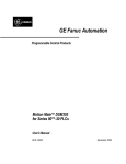
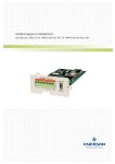
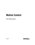
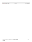
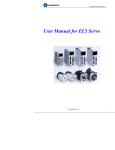
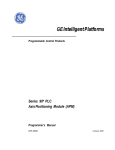
Figures 2-1and 2-2 illustrate typical Z-Series and V-Series amplifiers.
2.1
Feature Location
GE Fanuc
SL Series
Keypad / Display
(See Chapter 8)
MODE
SET
Test Points - IM, SP, G
(See Chapter 2)
IM SP G
AC Line Power
Connections
(See Chapter 4)
Regeneration
Resistor
Connections
(See Chapter 4)
Motor Power
Connections
(See Chapter 4)
R
S
T
P
B
U
V
W
Serial Connector - CN SER
(See Chapter 4)
36-pin Interface Connector - CN I/F
(See Chapter 4)
Encoder Connector - CN SIG
(See Chapter 4)
Ground
Connections
(See Chapter 4)
Hinged cover removed to
show terminals
Figure 2-1. Z-Series (30W - 750W) SL Amplifier Features
GFK-1581B
2-1
2
GE Fanuc
SL Series
Keypad / Display
(See Chapter 8)
MODE
SET
IM
SP
G
Test Points, IM, SP, G
(See Chapter 2)
R
AC Line Power
Connections
(See Chapter 4)
S
T
Control Power
Connections
(See Chapter 4)
r
t
No Connection
Serial Connector - CN SER
(See Chapter 4)
DL1
DL2
Regeneration
Resistor
Connections
(See Chapter 4)
No Connection
P
B
50-pin Interface Connector - CN I/F
(See Chapter 4)
N
U
Motor Power
Connections
(See Chapter 4)
V
W
E n c o d e r C o n n e c to r - C N S IG
(See Chapter 4)
Ground
Connections
(See Chapter 4)
Hinged cover removed to
show terminals
Figure 2-2. V-Series (1,000W – 5,000W) SL Amplifier Features
2-2
SL Series Servo User's Manual – August 2001
GFK-1581B
SL Amplifier Feature Overview
2.2
2
Rotational Direction Conventions
The direction of rotation of an SL Series motor is determined by the polarity of the command
signal and several user parameters used to reverse direction for a set mode of operation. The
operating modes shown below are configured by Parameter No. 02 (see Chapter 6-Parameters).
The SL Series servos use the following directional conventions:
•
Position Control Mode – The directional convention for the position control mode is
determined by Parameter No. 28. This applies to input signals PULS1, PULS2, SIGN1 and
SIGN2 on connector CN I/F pins 3-6 of the V-Series and pins 5-8 of the Z-Series. Directional
conventions for these signals are described in the Parameter No. 29 section of Chapter 6.
•
Velocity Control Mode - A positive velocity command input (SPR) is defined as a positive
voltage applied to connector CN I/F pin 14 with respect to pin 15 (ground). When a positive
command is applied and Parameter No. 14 -Speed Command Polarity is set to the default value
(1), the motor will rotate counter-clockwise when viewed looking into the motor shaft.
Changing Parameter No. 14 to 0 will reverse the direction of rotation for a positive command
input.
•
Torque Control Mode – A positive torque command input (TRQR) is defined as a positive
voltage applied to connector CN I/F pin 34 with respect to pin 35 (ground) in the Z-Series, and
pins 16 and 17, respectively, for the V-Series. When a positive command is applied and
Parameter No. 1B-Torque Command Polarity is set to the default value (1), the motor will
rotate counter-clockwise when viewed looking into the motor shaft. Changing Parameter No.
1B to 0 will reverse the direction of rotation for positive command input.
•
Rotational Convention for LED Display – The directional convention on the amplifier LED
display is fixed and cannot be changed by the user. Note that a positive value represents
counter-clockwise motion, and a negative value represents clockwise motion, when viewed
looking into the motor shaft.
Caution
When using the SL Series servos with an external position controller, such as the GE Fanuc
APM300 or DSM300 series, it may be necessary to change Parameter No. 0D to invert the encoder
output signal polarity when the command polarity is reversed in order to keep the command and
feedback signals in synch. If these two signals are not in phase, a runaway condition can be created
where the motor will accelerate to full speed and will not be under servo control. In that case,
removing AC power or the Servo Enable signal must be used to stop the motor. It is recommended
you use the Parameters to change signal polarity rather than reversing the physical wiring. As an
alternative, the APM and DSM controllers have an Axis Direction configuration parameter that can
be used to reverse motor direction for a given programmed move direction without inverting any of
the SL amplifier signals. The default for this parameter in the APM/DSM is positive.
GFK-1581B
Chapter 2 SL Amplifier Feature Overview
2-3
2
2.3
Specifications
Table 2-1. Z-Series Amplifier Specifications
Specification
Model Number
Continuous
Current
Peak Current
Amplifier Rating @ 20oC
Units
30 W
50 W
100 W
200 W
400 W
750 W
x = see Bus Power
Supply, below
SLA003x
SLA005x
SLA010x
SLA020x
SLA040x
SLA075x
115VAC Model
Arms
1.0
1.0
1.6
2.5
4.4
230VAC Model
Arms
1.0
1.0
1.0
1.6
2.5
115VAC Model
A0-p
4.3
4.3
6.9
10.5
18.3
230VAC Model
A0-p
4.3
4.3
4.3
6.9
10.5
Bus Power
Supply
x=1
x=2
170 – 253 VAC, 50/60 Hz, Single* or Three Phase
I/O Power
Supply
Voltage
12 to 24VDC ± 10%
Current
200 mA
Position Loop
0.25 ms
Loop Update
Time
Weight
Velocity Loop
0.25 ms
0.0417 ms
(Section 4.1.2)
0.0833 ms
Pulse Command
1 µs
Velocity Command
50 µs
Torque Command
50 µs
115 VAC Model
lb. [kg]
1.98 [0.9]
1.98 [0.9]
1.98 [0.9]
2.2 [1.0]
2.64 [1.2]
230 VAC Model
lb. [kg]
1.98 [0.9]
1.98 [0.9]
1.98 [0.9]
1.98 [0.9]
2.2 [1.0]
Turn On Voltage
External
Regenerative
Resistor Options
18.3
Single Phase 85 – 126 VAC, 50/60 Hz
Current Loop
Command Input
Filter Time
Constant
4.3
115 VAC Models: 195 VDC
2.64 [1.2]
230 VAC Models: 380 VDC
Continuous Power
115 VAC Models: 100 W
230 VAC Models: 225 W
Resistance
(GE Fanuc kit)
115 VAC Models: 50 Ω
230VAC Models: 100 Ω
Maximum Current
115VAC Models
8A
8A
8A
8A
12 A
N/A
230VAC Models
8A
8A
8A
8A
12 A
24 A
Environmental Data
Humidity (noncondensing)
Altitude
Ambient
Temperature
RH
90%
Feet [Meters]
3300 [1000]
o
C
0 to 50 operating
o
C
-20 to 80
Shock
G
15 (non-operating)
Vibration
G
0.5 @ 10-150 Hz
Storage
Temperature
* Single-phase operation of 230 VAC models rated 200 W and larger require derating of the motor torque by 2.5% per oC above 40oC up to 50oC
maximum.
2-4
SL Series Servo User's Manual – August 2001
GFK-1581B
SL Amplifier Feature Overview
2
Table 2-2. V-Series Amplifier Specifications
Specification
Amplifier Rating @ 20oC
Units
Model Number
Continuous Current
Arms
1000 W
2500 W
3500 W
5000 W
SLA1002
SLA2502
SLA3502
SLA5002
7.2
15.9
21.6
28.5
30
68
92
120
Peak Current
A0-p
Bus Power Supply
VAC
170 – 253 VAC, 50/60 Hz, Single* or Three Phase
Control Power
Supply
VAC
170-253VAC, 1φ, 50/60 Hz
Voltage
12 to 24VDC ± 10%
I/O Power Supply
Current
Position Loop
Loop Update Time
500 mA
0.26 ms
0.26 ms
0.26 ms
Velocity Loop
0.26 ms
0.26 ms
0.26 ms
0.26 ms
Current Loop
0.0868 ms
0.0868 ms
0.0868 ms
0.0868 ms
Pulse Command
1 µs
Velocity
Command
50 µs
Torque
Command
50 µs
Command Input
Filter Time
Constant
Weight
lb. [kg]
8.58 [3.9]
Turn On Voltage
External
Regenerative
Resistor Options
0.26 ms
9.46 [4.3]
21.8 [9.9]
21.8 [9.9]
380 VDC
Continuous
Power
300 W
1000 W
Resistance
(GE Fanuc kit)
20 Ω
15 Ω
Maximum
Current
40 A
40 A
40 A
40 A
Environmental Data
Humidity (noncondensing)
Altitude
Ambient
Temperature
RH
90%
Feet [Meters]
3300 [1000]
o
C
0 to 50 operating
o
C
-20 to 80
Shock
G
15 (non-operating)
Vibration
G
0.5 @ 10-150 Hz
Storage
Temperature
* Single-phase operation of 230 VAC models rated 200 W and larger require derating of the
motor torque by 2.5% per oC above 40oC up to 50oC maximum
.
GFK-1581B
Chapter 2 SL Amplifier Feature Overview
2-5
2
Table 2-3. Z-Series Motor Specifications
Motor Rating @ 20oC
SLM003
SLM005
115/230V
115/230V
W
30
50
100
200
400
750
Continuous Stall
Torque1
in-lb
[Nm]
0.84
[0.095]
1.42
[0.16]
2.83
[0.32]
5.66
[0.64]
11.5
[1.3]
21.2
[2.4]
Peak Torque
in-lb
[Nm]
2.48
[0.28]
4.25
[0.48]
8.4
[0.95]
16.9
[1.91]
33.6
[3.8]
62.8
[7.1]
Rated Speed
RPM
3000
3000
3000
3000
3000
3000
Maximum Speed
RPM
5000
5000
5000
5000
5000
4500
lb
[kg]
0.59
[0.27]
0.75
[0.34]
1.23
[0.56]
2.2
[1.0]
3.52
[1.6]
7.0
[3.2]
in-lb-s2 x 10-4
[kg-m2 x 10-4]
0.139
[0.016]
0.225
[0.025]
0.546
[0.062]
1.474
[0.17]
3.208
[0.36]
11.62
[1.31]
Shaft Thrust Load
lb
[kg]
6.6
[3]
13.2
[6]
13.2
[6]
22
[10]
22
[10]
33
[15]
Shaft Radial Load2
lb
[kg]
11
[5]
15.4
[7]
15.4
[7]
55
[25]
55
[25]
88
[40]
Mechanical Time
Constant
ms
1.8
1.2
0.8
0.77
0.62
0.63
0.48
0.54
0.45
Torque Constant
in-lb/A(rms)
[Nm/A(rms)]
0.91
[0.103]
1.42
[0.16]
1.86
[0.21]
3.28
[0.37]
2.39
[0.27]
3.72
[0.42]
2.66
[0.30]
4.78
[0.54]
5.4
[0.61]
Resistance (phase)
Ohms
4.0
4.2
1.9
5.7
0.91
2.3
0.41
1.46
0.43
Inductance (phase)
mH
2.4
2.8
1.7
5.0
3.2
7.8
1.9
5.1
3.2
Electrical Time
Constant
ms
0.6
0.67
0.89
0.88
3.5
3.4
4.6
3.5
7.4
1.0
1.0
1.6
1.0
2.5
1.6
4.4
2.5
4.3
Units
Specification
Output Power
Feedback
SLM010
115V
SLM020
230V
115V
230V
SLM040
115V
230V
SLM075
230V
2500 lines (10,000 counts/rev) Incremental Encoder (5 VDC±5% @ 0.3A; 250 kHz max.)
Weight
Rotor Inertia
Continuous Current
A(rms)
Optional Brake Data @ 20 C (backlash = ±0.1 )
o
o
Inertia Adder
in-lb-s2 x 10-4
[kg-m2 x10-4]
0.026
[0.003]
0.026
[0.003]
0.026
[0.003]
0.26
[0.03]
0.26
[0.03]
0.78
[0.09]
Weight Adder
lb
[kg]
0.44
[0.2]
0.42
[0.19]
0.44
[0.2]
0.88
[0.4]
0.88
[0.4]
1.54
[0.7]
Voltage
VDC± 10%
24
24
24
24
24
24
Current
A
0.26
0.26
0.26
0.36
0.36
0.43
Engage Time
ms
≤ 25
≤ 25
≤ 25
≤ 50
≤ 50
≤ 60
Release Time
ms
≤ 20
≤ 20
≤ 20
≤ 15
≤ 15
≤ 15
in-lb
[Nm]
2.6
[0.29]
2.6
[0.29]
2.6
[0.29]
10.8
[1.3]
10.8
[1.3]
21.7
[2.5]
Torque
Environmental Data
Humidity (noncondensing)
Ambient Temperature
(operating)
Storage Temperature
Vibration3
Shock
RH
85%
o
C
0 to 40
o
C
-20 to 80
G
5
G
10
1
Torque shown is available up to a certain Ambient Temp. See Speed/Torque curve notes.
Radial shaft loads are specified at a position centered along the length of the shaft.
3
Vibration tests are described in the section “Motor Vibration Testing.”
2
2-6
SL Series Servo User's Manual – August 2001
GFK-1581B
SL Amplifier Feature Overview
2
Table 2-4. V-Series Motor Specifications
Motor Rating @ 20oC
Specification
Output Power
Units
SLM100
SLM250
SLM350
SLM500
W
1000
2500
3500
5000
Continuous Stall Torque1
in-lb
[Nm]
28
[3.18]
70
[7.94]
97
[11]
140
[15.8]
Peak Torque
in-lb
[Nm]
84
[9.5]
210
[23.8]
294
[33.2]
421
[47.6]
Rated Speed
RPM
3000
3000
3000
3000
Maximum Speed
RPM
5000
5000
5000
4500
2500 lines (10,000 counts/rev) Incremental Encoder
(5 VDC±5% @ 0.3A; 250 kHz max.)
9.9
16.5
24
38
[4.5]
[7.5]
[10.9]
[17.3]
Feedback
Weight
lb
[kg]
in-lb-s2 x 10-4
[kg-m2 x 10-4]
14.91
[1.69]
38.14
[4.31]
69.92
[7.90]
157.5
[17.8]
Shaft Thrust Load
lb
[kg]
33
[15]
44
[20]
44
[20]
77
[35]
Shaft Radial Load2
lb
[kg]
88
[40]
110
[50]
110
[50]
176
[80]
Mechanical Time Constant
ms
0.78
0.52
0.45
0.46
in-lb/A(rms)
[Nm/A(rms)]
3.9
[0.44]
4.34
[0.49]
4.51
[0.51]
5.04
[0.57]
Resistance (phase)
Ohms
0.27
0.1
0.05
0.028
Inductance (phase)
mH
1.8
1.1
1
0.56
Electrical Time Constant
ms
6.7
11
20
20
A(rms)
7.2
15.9
21.6
28.5
Rotor Inertia
Torque Constant
Continuous Current
Optional Brake Data @ 20oC (backlash = ± 0.1o)
Inertia Adder
in-lb-s2 x 10-4
[kg-m2 x10-4]
2.25
[0.26]
3.81
[0.43]
6.99
[0.79]
16.82
[1.9]
Weight Adder
lb
[kg]
1.32
[0.6]
3.08
[1.4]
3.74
[1.7]
4.18
[1.9]
Voltage
VDC± 10%
24
24
24
24
Current
A
0.74
0.81
0.81
0.90
Engage Time
ms
≤ 50
≤ 50
≤ 80
≤ 110
Release Time
ms
≤ 15
≤ 15
≤ 15
≤ 50
in-lb
[Nm]
43.3
[4.9]
69
[7.8]
104
[11.8]
143
[16.2]
Torque
Environmental Data
Humidity (non-condensing)
Ambient Temperature
(operating)
Storage Temperature
Vibration 3
Shock
RH
85%
o
0 to 40
o
C
G
-20 to 80
5
G
10
C
1
Torque shown is available up to a certain Ambient Temp. See Speed/Torque curve notes.
Radial shaft loads are specified at a position centered along the length of the shaft.
3
Vibration tests are described in the next section “Motor Vibration Testing.”
2
GFK-1581B
Chapter 2 SL Amplifier Feature Overview
2-7
2
Motor Vibration Testing
There are two vibration tests for the SL series motors:
2-8
•
Sweep Test. The motor is subjected to a 5G variable frequency test for eight hours in each of
three axes (X, Y, Z). For the purpose of these tests, X axis is parallel with the motor shaft, Y
axis is parallel with the encoder connector, and Z axis is at a 90 degree angle to X and Y. In
this test, the vibration frequency increases from 20 to 3000 Hz. over a two minutes span, then
decreases from 3000 to 20 Hz over a two minutes span. This pattern is repeated for a period
of eight hours.
•
Resonance Point Test. First, the resonant frequency having the highest vibration is identified
while testing the motor with a 5G variable frequency (20 to 3000 Hz.) in three directions (X,
Y, Z). Then, the motor is vibrated 10 million times in each direction (X, Y, Z) at the
identified resonant frequency.
SL Series Servo User's Manual – August 2001
GFK-1581B
SL Amplifier Feature Overview
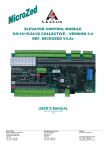
2.4
Motor Speed/Torque Curves
2.4.1
Z-Series Performance Curves
SLM005 (50 Watt)
3.0 (0.34)
6 (0.68)
2.5 (0.28)
5 (0.56)
Torque in- b (Nm)
Torque in- lb (Nm)
SLM003 (30 Watt)
2.0 (0.23)
1.5 (0.17)
1.0 (0.11)
0.5 (0.05)
0
4 (0.45)
3 (0.34)
2 (0.23)
1 (0.11)
0
1000 2000 3000 4000 5000 6000
Speed (RPM)
SLM020 (200 Watt)
18 (2.03)
8 (0.90)
15 (1.69)
Torque in- lb (Nm)
orque in- lb (Nm)
SLM010 (100 Watt)
6 (0.68)
4 (0.45)
2 (0.23)
12 (1.36)
230 VAC
6 (0.68)
3 (0.34)
0
1000 2000 3000 4000 5000 6000
SLM040 (400 Watt)
SLM075 (750 Watt)
66 (7.46)
30 (3.39)
24 (2.71)
N
115 VAC
230 VAC
18 (2.03)
12 (1.36)
(
lb
To
rq
ue
in-
55 (6.21)
44 (4.97)
33 (3.73)
22 (2.48)
11 (1.24)
6 (0.68)
0
1000 2000 3000 4000 5000 6000
Speed (RPM)
36 (4.07)
(
lb
To
rq
ue
in-
115 VAC
9 (1.02)
Speed (RPM)
N
1000 2000 3000 4000 5000 6000
Speed (RPM)
10 (1.13)
0
2
1000 2000 3000 4000 5000 6000
Speed (RPM)
0
1000 2000 3000 4000 5000 6000
Speed (RPM)
Continuous Torque
Intermittent Torque
Note: Continuous torque available for each motor model depends on the ambient temperature. These curves depict the
maximum continuous torque available for each model up to the following ambient temperatures:
• SLM003, SLM075 = 40 oC
• SLM005, SLM040 = 20oC
• SLM010, SLM020 = 30oC
Higher ambient temperatures require motor derating as shown in the temperature derating curves later in this chapter.
GFK-1581B
Chapter 2 SL Amplifier Feature Overview
2-9
2
2.4.2
V-Series Performance Curves
SLM250 (2500 Watt)
SLM100 (1000 Watt)
T o rqu e in -lb ( N m )
T o rqu e in -lb ( N m )
90 (10.2)
75 (8.47)
60 (6.78)
45 (5.08)
30 (3.39)
200 (22.6)
160 (18.1)
120 (13.6)
80 (9.04)
40 (4.52)
15 (1.69)
0
240 (27.1)
0
1000 2000 3000 4000 5000 6000
SLM0350 (3500 Watt)
SLM0500 (5000 Watt)
450 (50.8)
T o rqu e in -lb ( N m )
T o rqu e in -lb ( N m )
300 (33.9)
240 (27.1)
180 (20.3)
120 (13.6)
60 (6.78)
0
1000 2000 3000 4000 5000 6000
Speed (RPM)
Speed (RPM)
1000 2000 3000 4000 5000 6000
Speed (RPM)
375 (42.4)
300 (33.9)
225 (25.4)
150 (16.9)
75 (8.47)
0
1000 2000 3000 4000 5000 6000
Speed (RPM)
Continuous Torque
Intermittent Torque
Note: Continuous torque available for each motor model depends on the ambient temperature. These
curves depict the maximum continuous torque available for each model up to the following ambient
temperatures:
• SLM100 = 40 oC
• SLM250, SLM500 = 20oC
• SLM350 = 30oC
Higher ambient temperatures require motor derating as shown in the temperature derating curves
2-10
SL Series Servo User's Manual – August 2001
GFK-1581B
2
SL Amplifier Feature Overview
2.4.3
Derating Based on Ambient Temperature
The SL Series motors produce the continuous torque shown in the speed/torque curves (Section
2.4), up to certain ambient temperature limits depending on the motor model. The following curves
depict the continuous torque derating required for operation in higher ambient temperatures. The
intermittent torque available does not need to be derated.
Motor Derating Based on Ambient Temperature
SLM010
100
90
0
10
20
30
40
50
Motor Rated Torque Output (%)
Motor Rated Torque Output (%)
SLM005 / SLM040
100
95
0
Motor Ambient Temperature ( oC)
90
20
30
40
50
Motor Rated Torque Output (%)
Motor Rated Torque Output (%)
100
10
0
Motor Rated Torque Output (%)
Motor Rated Torque Output (%)
70
30
50
10
40
20
30
40
50
SLM350
100
20
40
Motor Ambient Temperature ( oC)
SLM250 / SLM500
10
30
100
95
90
Motor Ambient Temperature ( oC)
0
20
SLM003 / SLM075 / SLM100
SLM020
0
10
Motor Ambient Temperature ( oC)
50
Motor Ambient Temperature ( oC)
100
70
0
10
20
30
40
50
Motor Ambient Temperature ( oC)
Amplifier Derating for 230 VAC Single Phase Operation
Although the 230 VAC amplifiers can be operated with a single-phase input, they must be derated
at ambient temperatures above 40°C, as shown in the following graph. This derating is concurrent
with any derating of the motor output due to the motor ambient temperature, so the worst-case
derating should be used. For example, lets examine the application of a 3500 Watt motor and
amplifier where the amplifier is run on single phase in a 50oC ambient and the motor is run in a
GFK-1581B
Chapter 2 SL Amplifier Feature Overview
2-11
2
Motor Rated Torque Output (%)
40oC ambient. Comparing the graph for the SLM350 motor to the graph below, we see that the
motor derating required for 40oC operation (30%) is higher than the motor derating required for
50oC single-phase amplifier operation (25%). So the 30% derating figure is used, which protects
both motor and amplifier from thermal overload.
100
75
0
10
20
30
Amplifier Ambient Temperature
2.5
40
50
( oC)
Motor Sealing
The SL series motors are designed to comply with an IP65 protection rating excluding the cable
connector and shaft. The V-Series motors include a shaft oil seal as a standard feature while the ZSeries motors do not include a shaft seal. Adequate precautions should be taken when mounting
the motors to ensure proper protection against excessive exposure to fluids and spray.
2.6
Motor Holding Brakes
As an option the SL Series motors are available with an integral parking brake. The brakes are
designed for failsafe operation and must be energized to release the brake.
Note
The brake should only be used to hold motor position once the axis is
stopped. Using the brake to stop a moving load may result in damage or
premature failure of the brake mechanism. Use the dynamic brake function
(see Section 2.8) or an external mechanical brake to stop moving loads
during an emergency stop or loss of power.
The brakes require a finite time to engage and release the load as shown in the brake specifications
in Tables 2-3 and 2-4. These times must be considered in the brake sequencing logic when
employing brake motors on vertical axes to prevent the load from falling. The servo amplifier must
remain enabled until the brake is fully engaged or the load will not be adequately restrained.
The SL amplifiers include a brake control output (BRK-OFF) that may be used to indirectly control
brake activation. This output must be connected to an interposing relay (coil rated for 12-24 VDC;
50mA maximum) in the brake power supply. For Z-Series amplifiers the BRK-OFF output shares
a terminal on the CN I/F interface connector with the servo ready (S-RDY) and zero speed detected
(ZSP) functions. These functions are mutually exclusive and are selected by Parameter 3F.
Parameter Nos. 0E and 0F determine the timing of the BRK-OFF output under various operating
conditions. See Chapters 5 and 6 for more details on these parameters. See Chapter 4, Section
4.1.2 for brake wiring details and diagrams.
The brake power supply is the user’s responsibility and must comply with the brake specifications
shown in Tables 2-3 and 2-4. GE Fanuc offers a 24VDC, 5 amp DIN-rail mounted power supply
(IC690PWR024) that may be appropriate as a brake supply on multi-axis systems. A panel
mounting conversion kit is also available (IC690PAC001). Brake power cables are available from
GE Fanuc in several pre-finished lengths as shown in Table 4-4.
2-12
SL Series Servo User's Manual – August 2001
GFK-1581B
SL Amplifier Feature Overview
2.7
2
NEMA Motor Mounting
The SL Series servo motors with ratings up to 1000 Watt are designed with standard NEMA shaft
and flange sizes as shown in Table 2-5 to facilitate mounting to readily available gear reducers and
actuators. Motor models larger than 1kW have metric mounting configurations. For dimensional
information on these motors (including mounting dimensions), please see the mechanical drawings
in Chapter 3.
Table 2-5. NEMA Mounting Sizes for SL Motors (30 to 1000 W only)
NEMA Size
NEMA 23
NEMA 34
NEMA 42
Motor Model
SLM003
X
SLM005
X
SLM010
X
SLM020
X
SLM040 SLM075* SLM100
X
X
X
* The SLM075 (750 Watt) model has an oversized shaft diameter for the NEMA 34 frame size.
This is required because the torque rating of this motor exceeds the capacity of the standard NEMA
34 shaft size. This condition is typical of high performance brushless servo motors that produce
high peak torque relative to their frame size. For details about motor installation and dimensions,
see Section 3-3.
2.8
Dynamic Brake Function
SL Series servos have a built-in dynamic brake for emergency stops. The dynamic brake uses the
stored kinetic energy in the motor to generate braking torque. Since the braking torque is
proportional to motor speed, the motor decelerates along an exponential velocity profile to a stop.
The dynamic brake is activated in the following cases:
•
When you turn off the main AC line power.
•
When you disable the amplifier by removing the SRV-ON signal (see Section 5.7.2) the
dynamic braking action is determined by the setting of Parameter No.0A (V-Series) or
Parameter No.3E (Z-Series) as described in Section 6.3.
•
When a protective (alarm) function is activated you can select the dynamic brake action using
Parameter No.0A (V-Series) or Parameter No. 3D (Z-Series) as described in Section 6.3.
•
If the CW overtravel limit switch (connected to the CWL input on connector CN I/F) is opened
while the motor is running in the CW direction (viewed from the motor shaft). You can select
whether or not to activate the dynamic brake using Parameter No. 0A as described in Section
6.3 (both V-Series and Z-Series).
•
If the CCW overtravel limit switch (connected to the CCWL input on connector CN I/F) is
opened while the motor is running in the CCW direction (viewed from the motor shaft). You
can select whether or not to activate the dynamic brake using Parameter No. 0A as described in
Section 6.3 (both V-Series and Z-Series).
Note
The dynamic brake is designed for emergency stops and should not be activated repeatedly over a
short time period or the amplifier may be damaged.
GFK-1581B
Chapter 2 SL Amplifier Feature Overview
2-13
2
The dynamic brake is effective in reducing the stopping distance of the motor when compared to
allowing the motor to coast to a stop, but it is not as effective as a mechanical brake for holding
axis position. Applications using vertical axes or other axes that require the load to be locked into
position for long periods or while amplifier power is removed should use a motor with the optional
holding brake.
2.9
Configuration and Monitoring
The SL Series amplifiers offer a wide variety of configuration options, tuning and monitoring
functions. These functions are accessed using either the front panel keypad/display or the SLconfig
PC based software. For initial configuration, the SLconfig software is more efficient and provides
the ability to save the settings to a file for repeat applications or archiving. The keypad is
convenient for quick adjustments during start-up or troubleshooting. The SL amplifier keypad is a
tactile membrane type with five push buttons to navigate through the function menus.
The amplifiers also include a six-digit LED display that is used to display the menu functions,
parameter data values, and a broad range of system status information. The user can configure
motor speed, torque or position error as the default display on power-up (see Parameter No.01).
When a fault occurs, the display will flash and the most recent eight errors can be displayed and the
keypad can be used to clear the current alarm. Chapter 9 describes the protective functions of the
SL Series and Chapter 8 provides details on how to use the keypad and SLconfig functions.
The SL amplifiers also include two test points on the front panel for monitoring motor speed
feedback, position error (SP) or commanded torque (IM). These test points are bi-polar analog
signals with user defined scaling (Parameter No.08) and are also available as outputs on the CN I/F
interface connector for hardwired continuous monitoring by the machine controller or panel meter.
Other I/O available to monitor system status include a servo ready output (S-RDY), zero speed
detection output (ZSP), alarm output (ALM), At-Speed/In-Position output (COIN) and, on the VSeries amplifiers only, an In-Torque-Limit output (TLC) and 3-bit error code output
(EXOUT0,1,2).
2.10
Control Modes
The SL Series amplifiers can be configured for the following operating modes:
1.
Position Control Mode – Accepts a variety of pulse command inputs to control the position of
the motor. The user can configure the amplifier for CW/CCW pulse commands,
Pulse/Direction commands or A/B Phase (encoder follower) pulse commands. This mode
provides a convenient way to upgrade stepper systems to improve performance or for simple
master/slave applications using a fixed (user defined) follower ratio. In this mode, the user can
configure a position error limit that will trip the drive when exceeded and independent analog
inputs (CWTL and CCWTL) are available to dynamically limit torque in the CW and CCW
directions. The position error limit is user definable and can be disabled. A discrete input is
available (CL) to allow the machine control system to clear the position error counter.
Adjustments for the Position Control Mode include:
•
•
•
•
•
2-14
Position Loop Gain (Parameter No.20)
In-Position Detection Range (Parameter No.22)
Position Error Limit (Parameter No.23)
Position Error Limit Inhibit (Parameter No.24)
Pulse Command Ratio (Parameter Nos.25 and 26)
SL Series Servo User's Manual – August 2001
GFK-1581B
SL Amplifier Feature Overview
•
•
•
•
•
•
•
2.
Quadrature Pulse Input Multiplier (Parameter No.27)
Pulse Command Input Polarity (Parameter No.28)
Pulse Command Input Mode (Parameter No.29)
Second Position Loop Gain (Parameter No.32; Z-Series only)
Second Numerator of Pulse Command Ratio (Parameter No.35; Z-Series only)
Pulse Command Filter Delay (Parameter No.36; Z-Series only)
Position Error Counter Clear Mode (Parameter No.3C; Z-Series only)
Torque Control Mode – Accepts an analog torque command for motion controllers that
require a torque command interface. This mode can also be used for direct control of torque or
web tension. The SL amplifiers include an additional analog input (SPL) that can be used to
dynamically vary the speed limit for torque mode control. Alternatively, the internal speed
presets described above can be used for one or more fixed speed limits. Adjustments for
Torque Control Mode include:
•
•
•
•
3.
2
Torque Command Scaling (Parameter No.1A)
Torque Command Polarity (Parameter No.1B)
Torque Command Offset (Parameter No.1C)
Torque Command Filter (Parameter No.1D)
Velocity Control Mode (default) – This mode can be configured to accept either an analog
velocity command or multiple internal preset speed commands selected using discrete inputs.
The Z-Series amplifier supports up to four internal speed settings while the V-Series amplifiers
support two speed presets. The Z-Series also has a mode where the user can switch between
the analog command and up to three preset speeds using discrete inputs. When used with an
external position controller, such as the GE Fanuc APM300 or DSM300 Series, the SL
amplifier provides incremental encoder feedback to close the position loop. Independent
analog inputs (CWTL and CCWTL) are available to dynamically limit torque in the CW and
CCW directions. For speed control applications, the ZEROSPD clamp input can be used to
prevent servo drift when the motor is stopped for long periods of time. Adjustments for
Velocity Control Mode include:
•
•
•
•
•
•
•
•
•
•
•
•
•
•
•
Velocity Loop Gain (Parameter No.03)
Velocity Loop Integration Time Constant (Parameter No.04)
Velocity Feedback Filter (Parameter No.05)
Velocity Command Scaling (Parameter No.13)
Velocity Command Polarity (Parameter No.14)
Velocity Command Offset (Parameter No.15)
Internal/External Velocity Command Selection (Parameter No.16)
First Internal Speed (Parameter No.18)
Second Internal Speed (Parameter No.19)
Velocity Feed Forward (Parameter No.21)
Velocity Feed Forward Filter Time Constant (Parameter No.2B)
Second Velocity Loop Gain (Parameter No.30; Z-Series only)
Second Velocity Loop Integration Time Constant (Parameter No.31; Z-Series only)
Third Internal Speed (Parameter No.38; Z-Series only)
Fourth Internal Speed (Parameter No.39; Z-Series only)
The SL amplifiers can also be configured for dual control mode operation (Parameter No.02) where
any two of these control modes can be selected using the C-MODE discrete input. Chapter 6
provides detailed descriptions of the parameters used to configure these modes.
GFK-1581B
Chapter 2 SL Amplifier Feature Overview
2-15
2
2.11
Gain Switching
The Z-Series amplifiers allow the user to configure two different gain setting for the Position and
Velocity Control Modes. The gains are configured by various parameter settings and Parameter
No.33 determines the event that initiates the gain switch. The gain switch can be disabled,
automatic (Position Control Mode only) or initiated by activating the GAIN input. For the
automatic gain switching mode, Parameter No.34 configures a delay time used to initiate the
second gain values. This time delay is referenced to the falling edge of the final pulse of the move
command. For more information on gain switching, refer to the descriptions for the following
parameters in Chapter 6:
•
•
•
•
•
2-16
2nd Velocity Loop Gain (Parameter No.30)
2nd Velocity Loop Integration Time Constant (Parameter No.31)
2nd Position Loop Gain (Parameter No.32)
Second Gain Switching Mode (Parameter No.33)
Automatic Gain Switching Delay Time (Parameter No.34)
SL Series Servo User's Manual – August 2001
GFK-1581B
SL Amplifier Feature Overview
2.12
2
Agency Compliance
The table below lists the compliance status of each SL series product for the following standards:
•
UL: Refers to United States UL listing, UL508C (File Number E164620).
•
C-UL: Refers to Canadian UL listing.
•
CE: Refers to European Community’s Low Voltage and EMC Directives (see Appendix B
for application details to ensure compliance).
Table 2-6. SL Series Products Agency Compliance
Product
UL
C-UL
CE
SLA003x* Amplifier
Yes
Yes
Yes
SLA005x* Amplifier
Yes
Yes
Yes
SLA010x* Amplifier
Yes
Yes
Yes
SLA020x* Amplifier
Yes
Yes
Yes
SLA040x* Amplifier
Yes
Yes
Yes
SLA075x* Amplifier
Yes
Yes
Yes
SLA1002 Amplifier
Yes
Yes
Yes
SLA2502 Amplifier
No
No
Yes
SLA3502 Amplifier
No
No
Yes
SLA5002 Amplifier
No
No
Yes
SLM003 Motor
Yes
No
Yes
SLM005 Motor
Yes
No
Yes
SLM010 Motor
Yes
No
Yes
SLM040 Motor
Yes
Yes
Yes
SLM075 Motor
Yes
Yes
Yes
SLM100 Motor
Yes
Yes
Yes
SLM250 Motor
No
No
Yes
SLM350 Motor
No
No
Yes
SLM500 Motor
No
No
Yes
*Note: For amplifier model numbers shown with an x suffix, such as SLA003x, the x is a
placeholder for a number that specifies the amplifier’s bus power supply voltage. If the
suffix is 1, the voltage is 115VAC; if the suffix is 2, the voltage is 230VAC. For example,
SLA0031 specifies an SLA003-size (30-watt) amplifier with a 115VAC bus power supply
voltage rating. SLA0032 specifies the same size amplifier, but with a 230VAC bus power
supply voltage rating. See Table 2-1 for more details.
GFK-1581B
Chapter 2 SL Amplifier Feature Overview
2-17
Installation Guidelines
Chapter
3
3.1
Amplifier Mounting Guidelines and Environmental
Conditions
It is the user’s responsibility to install the components in a suitable location. The servo amplifier must
be installed in a location that satisfies the following environmental conditions:
1.
Atmosphere: The circuitry and cooling fans must not be exposed to any corrosive or conductive
contaminants.
2.
Ambient temperature:
0°C to +50°C (operating)
-20°C to 80°C (storage)
Install the amplifier into ambient temperature conditions within the range of 0° C to +50° C. If the
temperature exceeds this range, it may cause malfunction or damage to the amplifier. For
230VAC models using a single phase power supply it is necessary to limit the maximum ambient
temperature to 40oC for full rated output.
The servo amplifier heatsink and motor generate high temperatures. If the amplifier is housed in
an enclosed control cabinet this heat load must be considered when evaluating the enclosure
cooling requirements (see Section 3.6-Power Dissipation for details on amplifier losses). Use heat
exchangers or cooling devices to maintain an ambient temperature of 50° C or less.
3.
Humidity: 90% relative humidity or less (non-condensing)
4.
Vibration: Less than 0.5 G at 10-150Hz
5.
Shock:
6.
No more than 1000m (3300 ft) above sea level for full rating. Contact GE Fanuc
Altitude:
Applications Engineering for derating at higher elevations.
7.
Ventilation: This amplifier is designed for vertical installation to ensure proper cooling. Install
the amplifier with sufficient space for ventilation. Avoid mounting wireways and other adjacent
components too close to the heatsink, top or bottom of the amplifier.
8.
Location:
amplifier:
•
GFK-1581B
Less than 15 G (non-operating)
Keep the following location guidelines in mind when selecting a site for the
Do not install in places with high temperature, high humidity, dust, dirt, conductive powder or
particulate, combustible gasses, or metal chips.
3-1
3
3.2
•
Avoid places exposed to direct sunlight.
•
Mount only to noncombustible materials such as metal.
•
Do not stand/step on or put heavy articles on the amplifier or motor.
•
The amplifier housing is rated IP20 and is not a waterproof enclosure. Do not use outdoors or
in any unprotected environment.
•
Avoid locations where there is exposure to radiation such as microwave, ultraviolet, laser
light or X-rays.
•
Do not block the inlet/exhaust ports, and prevent foreign objects from getting into the ports.
•
Do not apply excessive stress, put heavy articles on, or pinch the cables.
•
Do not install the amplifier near heating elements such as cabinet heaters or large wire wound
resistors. When such installation is unavoidable, provide a thermal shield between the servo
amplifier and the heating elements.
•
Mount amplifiers and other heat producing components higher in the enclosure to avoid
overheating other sensitive electronics installed in the same cabinet.
•
The V-Series amplifier has mounting tabs that allows mounting either flush to a panel or
through a cutout in the panel. When mounting through a panel, make sure the panel is of
sufficient gauge to support the weight of the amplifier.
Installing the Amplifier
The SL Series Amplifiers are designed for panel mounting in electrical enclosures designed for
industrial applications. Enclosure cooling or ventilation must be adequate to maintain the ambient
temperature to within the component’s specifications. Mount amplifiers vertically for proper cooling.
1.
Firmly install the amplifier with screws and bolts without applying stress such as bending and
twisting to the amplifier main unit.
2.
Use M4 (#8) or M5 (#12) mounting screws or bolts.
3.
Allow reasonable mounting clearance between adjacent units to ensure proper ventilation.
Cautions and Warnings for
Installation and Operation
Since a misuse of the amplifier may lead to improper operation, or may damage
the amplifier, carefully read the following cautions and warnings:
3-2
•
Be sure to ground the amplifier properly using the ground terminals on the front of the amplifier.
Proper grounding includes conforming to applicable national and local electrical codes. Refer to
Chapter 4 for instructions.
•
Do not apply higher than rated voltage to the power input terminals (R, S, and T).
•
Do not apply the main input power to terminals other than terminals R, S, and T or damage will
occur. Refer to Section 5-1-1 for wiring information.
SL Series Servo User's Manual – August 2001
GFK-1581B
3
Installation Guidelines
3.3
•
The power supply uses a capacitor filter. When you turn on power, a high charging current flows
and you may see a large voltage drop. We recommend that you use an independent power supply
for the amplifier(s) or install line reactors to limit the charging current.
•
Do not perform a dielectric strength test or megger test on the amplifier or damage may occur.
(When you perform a dielectric strength test or megger test to an external circuit, please
disconnect all terminals to the amplifier so that no test voltage is applied to the amplifier.)
•
Do not operate the amplifier under overload conditions (such as continuous overcurrent
operation).
•
When power is turned off, allow about 11 seconds before re-applying power. If this interval is too
short, the system may not start up normally because its internal circuit is not properly initialized.
•
If you use a ground fault breaker, use one rated for "Inverter," to withstand high frequency leakage
current.
•
Use the motor and amplifiers only in the designated combinations (Table 1-1 and Table 1-2).
•
When transporting, use caution to prevent damage to the servo components. Do not grasp the
cables when carrying.
•
Do not apply excessive force to the amplifier front panel and side plates.
Installing the Motor
The SL Series servo motors are designed for either vertical or horizontal mounting and have a
protection rating of IP65 (not including the connectors and shaft). The motors should be mounted in a
location where the environmental conditions are within the specifications stated in Table 2-3 and Table
2-4. Use the following guidelines when mounting the motors:
GFK-1581B
•
Observe the shaft radial and thrust load limits shown in Table 2-3 and Table 2-4. Loads exceeding
these limits will cause premature failure of the motor. Excessive belt tension could cause bearing
or shaft failure.
•
Be sure to ground the motor using the ground wire in the motor power cable.
•
Ensure that the motor cables are free from excessive stress, stretching, pinching or bending.
•
To avoid damage, do not carry a motor by holding the cables or shaft.
•
Do not apply excessive axial force or impact loads when installing the motor coupling or shaft
pulley or the encoder may be damaged. See axial load limit ratings in tables 2-3 and 2-4.
•
Install the motor in a location free from corrosive contaminants, dust, excessive water spray, or
combustible gas.
•
The shaft of the motor is treated with grease (Shell Oil Alvania No. 2) for corrosion protection
during storage. Consider the effect of the grease on any plastic parts that are mated with the shaft.
•
The optional motor brake should be used for holding stationary loads only. Do not use this brake
to stop a moving load or reduced life or damage to the brake may occur. Apply this brake only
after the motor is stopped. Use the dynamic braking feature of the amplifier to stop moving loads
more quickly when power is removed from the amplifier (see Section 2.6).
Chapter 3 Installation Guidelines
3-3
3
3.4
Mounting Dimensions
3.4.1
Z-Series Amplifier Dimensions
φ 0.205 (5.2)
GE Fanuc
MODE
SL Series
SET
IM SP G
GE Fanuc
SL Series Amplifier
IC800SLA0402
R
S
T
6.61
(168)
6.3
(160)
5.91
(150)
P
B
U
C
UL
US
V
W
0.205 (5.2)
0.99 (25)
A
1.98 (50)
Model
30-100 Watt
200 Watt
400 Watt
750 Watt
0.16 (4)
B
Diminensions in inches (mm)
120V Versions
A
B
0
5.12 (130)
0.59 (15)
5.12 (130)
0.59 (15)
6.69 (170)
N/A
N/A
230V Versions
A
B
0
5.12 (130)
0
5.12 (130)
0.59 (15)
5.12 (130)
0.59 (15)
6.69 (170)
Figure 3-1. Z-Series Amplifier Dimensions
3-4
SL Series Servo User's Manual – August 2001
GFK-1581B
3
Installation Guidelines
3.4.2
V-Series Amplifier Dimensions
φ 0.205 (5.2)
Alternate Mounting
Tab Locations
GE Fanuc
MODE
SL Series
SET
IM
SP
G
R
GE Fanuc
SL Series Amplifier
S
IC800SLAxxxx
T
9.84
(250)
r
t
9.25
(235)
8.66
(220)
DL1
DL2
C
UL
US
8.90
(226)
P
B
N
U
For 2,500
Watt
Amplifier
V
W
For 1,000
Watt
Amplifier
0.79
(20)
0.205 (5.2)
1.38 (35)
0.04 (1)
8.08 (205)
1.97 (50)
2.76 (70)
3.74 (95)
Diminensions in inches (mm)
4.72 (120)
Figure 3-2. V-Series Amplifier Dimensions for 1,000 and 2,500 Watt Sizes
φ 0.205 (5.2)
Alternate Mounting Plate Locations
GE
SL
MODE
SET
IM SP G
GE Fanuc
SL Series Amplifier
R
IC800SLAxxxx
S
9.84
(250)
T
C
9.25
(235)
8.66
(220)
r
t
DL1
UL
US
8.90
(226)
P
B
U
V
W
0.205 (5.2)
0.98 (25)
0.79
(20)
0.394 (10)
1.38
(35)
12.8 (325)
2.95 (75)
3.937 (100)
5.906 (150)
Diminensions in inches
Figure 3-3. V-Series Amplifier Dimensions for 3,000 and 5,000 Watt Sizes
GFK-1581B
Chapter 3 Installation Guidelines
3-5
3
3.5
Motor Mounting Dimensions
Lead Lengths
C1 (encoder cable) = 9.055 inches (230 mm)
C2 (both motor and brake cables) = 7.874 inches (200 mm)
L1
C1
AH
L2
BB
C
2
4 x H dia on
Bolt circle AJ
AJ
U AK
G
A
L
Model
Units
A
AH
AJ
AK
BB
G
SLM003
(30 Watts)
inches
2.27 ± 0.024
0.7874 ± 0.028
2.625 ± 0.024
1.502+−00.001
0.118 ± 0.008
0.236 ± 0.012
mm
57.658 ± 0.6
20 ± 0.7
66.675 ± 0.6
38.1508+−00.025
SLM005
(50 Watts)
inches
2.27 ± 0.024
0.7874 ± 0.028
2.625 ± 0.024
1.502+−00.001
mm
57.658 ± 0.6
20 ± 0.7
66.675 ± 0.6
38.1508+−00.025
SLM010
(100 Watts)
inches
2.27 ± 0.024
0.7874 ± 0.028
2.625 ± 0.024
1.502+−00.001
66.675 ± 0.6
38.1508+−00.025
mm
57.658 ± 0.6
20 ± 0.7
3 ± 0.2
0.118 ± 0.008
3 ± 0.2
0.118 ± 0.008
3 ± 0.2
6 ± 0.3
0.236 ± 0.012
6 ± 0.3
0.236 ± 0.012
6 ± 0.3
Model
Units
H
U
L
L
(With
Brake)
L1
L1
(With
Brake)
L2 (With or
Without Brake)
SLM003
(30 Watts)
inches
0.1968 ± 0.010
0.25+−00.0004
2.559
3.819
1.772
3.031
0.709
mm
5 ± 0.25
6.35+−00.009
65
97
45
77
18
SLM005
(50 Watts)
inches
0.1968 ± 0.010
0.25+−00.0004
2.874
4.134
2.087
3.346
1.024
mm
5 ± 0.25
6.35+−00.009
73
105
53
85
26
SLM010
(100 Watts)
inches
0.1968 ± 0.010
0.25+−00.0004
4.055
5.315
3.268
4.528
2.205
5 ± 0.25
6.35+−00.009
103
135
83
115
56
mm
Figure 3-4. Dimensions for 30-100 Watt SL Series Motors
3-6
SL Series Servo User's Manual – August 2001
GFK-1581B
3
Installation Guidelines
L1
C1
AH
L2
4 x H dia on
Bolt circle AJ
C
2
BB
AJ
XD
S
U
R
R
AK
G
A
L
Model
SLM020
(200 Watt)
Units
A
AH
AJ
AK
BB
G
inch
3.42 ± 0.024
1.181 ± 0.028
3.875 ± 0.024
2.877+−00.0012
0.118 ± 0.008
0.315 ± 0.012
mm
86.868 ± 0.6
30 ± 0.7
98.425 ± 0.6
73.0758+−00.030
3 ± 0.2
8 ± 0.3
H
0.2165 ± 0.010
5.5 ± 0.25
Model
Units
C1
C2
L1
L1 (With Brake)
L2 (With or Without
Brake)
SLM020
(200 Watt)
inch
8.662
7.874
2.854
4.154
1.535
mm
220
200
72.5
105.5
39
Model
Units
U
L
L
(With Brake)
R
S
XD
inch
0.375+−00.0004
3.701
5.000
0.3018+−00.015
0.125+−00.002
0.75+−00.016
mm
9.5250+−00.009
94
127
7.666+−00.381
3.175+−00.051
19.050+−00.4
SLM020
(200 Watt)
Figure 3-5. Dimensions for 200 Watt SL Series Motor
GFK-1581B
Chapter 3 Installation Guidelines
3-7
3
L1
C1
AH
L2
4 x H dia on
Bolt circle AJ
C
2
BB
AJ
XD
S
U
R
R
AK
G
A
L
Model
SLM040
(400 Watt)
Units
A
AH
AJ
AK
BB
G
H
0.118 ± 0.008
0.315 ± 0.012
0.2165 ± 0.010
3 ± 0.2
8 ± 0.3
5.5 ± 0.25
inch
3.42 ± 0.024
1.181 ± 0.028
3.875 ± 0.024
2.877+−00.0012
mm
86.868 ± 0.6
30 ± 0.7
98.425 ± 0.6
73.0758+−00.030
Model
Units
C1
C2
L1
L1 (With Brake)
L2 (With or Without
Brake)
SLM040
(400 Watt)
inch
8.662
7.874
4.016
5.315
2.697
mm
220
200
102
135
68.5
Model
SLM040
(400 Watt)
Units
U
L (Without
Brake)
L
(With Brake)
R
S
XD
inch
0.375+−00.0004
4.862
6.161
0.3018+−00.015
0.125+−00.002
0.75+−00.016
mm
9.5250+−00.009
123.5
156.5
7.666+−00.381
3.175+−00.051
19.050+−00.4
Figure 3-6. Dimensions for 400 Watt SL Series Motor
3-8
SL Series Servo User's Manual – August 2001
GFK-1581B
3
Installation Guidelines
L1
C1
AH
L2
4 x H dia on
Bolt circle AJ
C
2
BB
AJ
XD
S
U
R
R
AK
G
A
L
Model
SLM075
(750 Watt)
Units
A
AH
AJ
AK
BB
G
H
inch
3.42 ± 0.024
1.181 ± 0.028
3.875 ± 0.024
2.877+−00.0012
0.118 ± 0.008
0.315 ± 0.012
0.2165 ± 0.010
mm
86.868 ± 0.6
30 ± 0.7
98.425 ± 0.6
73.0758+−00.030
3 ± 0.2
8 ± 0.3
5.5 ± 0.25
Model
Units
C1
C2
L1
L1 (With Brake)
L2 (With or Without
Brake)
SLM075
(750 Watt)
inch
8.662
7.874
4.764
6.142
3.346
mm
220
200
121
156
85
Model
SLM075
(750 Watt)
Units
U
L (Without
Brake)
L
(With Brake)
R
S
XD
inch
0.625+−00.0004
5.610
6.988
0.5165+−00.015
0.1885+−00.002
0.952+−00.016
mm
15.875+−00.011
142.5
177.5
13.120+−00.383
4.788+−00.051
24.200+−00.4
Figure 3-7. Dimensions for 750 Watt SL Series Motor
GFK-1581B
Chapter 3 Installation Guidelines
3-9
3
L1
L2
AH
BB
C2
4 x H dia on
Bolt Circle AJ
C1
AJ
S
XD
U
AK
R
T
AL
G
L
A
Note: Shaft end play (axial) = 0.0118” (0.3 mm) or less
Model
Units
A
AH
AJ
AK
AL
BB
G
inch
4.38
1.378
4.95
2.188+−00.004
5.512
0.118
0.394
mm
111.25
35
125.73
55.575+−00.1
140
3
10
SLM250
mm
100
55
115
95+−00.035
135
3
10
SLM350
mm
120
55
130/145*
110+−00.035
162
3
12
SLM500
mm
130
65
145
110+−00.035
165
6
12
Model
Units
C1
C2
L1
L1 (W/Brake)
L2
L2 (W/Brake)
inch
3.31
3.62
6.012
7.087
3.858
4.843
mm
84
92
155
180
98
123
SLM250
mm
84
97
207
232
153
178
SLM350
mm
84
111
214
239
160
185
SLM500
mm
84
119
257
282
202
227
Model
Units
H
U
L
L (W/Brake)
R
S
T
XD
inch
0.2600
0.625+−00.0005
6.890
7.874
0.5165+−00.015
0.1885+−00.002
0.1885
1.000
mm
6.6
15.875+−00.013
175
200
13.120+−00.383
4.788+−00.051
4.788
25.4
SLM250
mm
9
19+−00.013
227
252
15.5
6+−00.036
6
42
SLM350
mm
9
22+−00.013
234
259
18
8+−00.036
7
41
SLM500
mm
9
24+−00.013
277
302
20
8+−00.036
7
51
SLM100
SLM100
SLM100
*Mounting holes on SLM350 are slotted to accommodate bolt circles (dimension AJ) from 130 through 145 mm.
Figure 3-8. Dimensions for 1000 Watt to 5000 W SL Series Motors
3-10
SL Series Servo User's Manual – August 2001
GFK-1581B
3
Installation Guidelines
3.6
Power Dissipation
Each SL Series Amplifier dissipates power that results in some enclosure heating. The table below
shows the approximate power dissipation for each amplifier operating at rated outputs for use in
determining enclosure size and cooling requirements. Values in the table do not include dissipation
from an optional regeneration resistor.
Table 3-1. Power Dissipation
GFK-1581B
Amplifier Model
Number
Description
Power Loss of
Amplifier (W)
IC800SLA0031
IC800SLA0051
30 Watt, 115 VAC
50 Watt, 115 VAC
14.5
17.0
IC800SLA0101
100 Watt, 115 VAC
21.4
IC800SLA0201
IC800SLA0401
IC800SLA0032
IC800SLA0052
200 Watt, 115 VAC
400 Watt, 115 VAC
30 Watt, 230 VAC
50 Watt, 230 VAC
29.8
42.1
19.0
19.5
IC800SLA0102
IC800SLA0202
IC800SLA0402
100 Watt, 230 VAC
200 Watt, 230 VAC
400 Watt, 230 VAC
20.7
25
27
IC800SLA0752
IC800SLA1002
IC800SLA2502
IC800SLA3502
750 Watt, 230 VAC
1000 Watt, 230 VAC
2500 Watt, 230 VAC
3500 Watt, 230 VAC
44
77
170
280
IC800SLA5002
5000 Watt, 230 VAC
280
Chapter 3 Installation Guidelines
3-11
Chapter Wiring
4
This chapter provides wiring guidelines for the SL amplifier power terminals, I/O and command
interface connector (CN I/F), encoder connector (CN SIG), and serial connector (CN SER). It also
describes installing the optional regeneration resistor and selecting AC incoming power wiring.
4.1
Wiring to the Amplifier Power Terminals
Use the following guidelines when connecting wires to the amplifier power terminals. Refer to
Figure 4-1 for example wiring diagrams.
1.
The cover of the power terminal block is secured with a screw. When wiring to the terminal
block, remove the screw and gently pull open the cover to release the snap detent.
2.
Tighten screw terminals to 7 lb-in. (0.79 Nm) maximum. Applying excessive torque to the
screws may break the terminals.
3.
Use wire that meets the following characteristics:
4.
•
Use 60/75°C or higher rated wire only
•
Use copper conductors only
For the main power supply and control power supply, apply voltage as indicated below:
Supply
Model
Line
AC Line
230 VAC
115 VAC
170 to 253 VAC
85 to 126 VAC
Control Power
GFK-1581B
230 VAC +10% –15% single phase (V-Series amplifiers only)
5.
The direction of rotation of the AC servo motor cannot be changed by exchanging the 3-phase
power wiring as with an induction motor. Be sure to correctly match the amplifier motor output
terminals with the motor power terminals. The direction of the motor can be changed using
configuration parameters on the SL amplifier (see Parameter No.14 in Chapter 6) or on a GE
Fanuc APM300 or DSM300 Series motion controllers.
6.
Use insulated spring spade terminals for connecting the lead wires to each terminal. The
terminals for amplifier models up to 2500 Watts use an M4 size screw (4 mm or 0.1575 inch
diameter) and can accommodate terminal connectors up to 0.25 inches (6.35mm) wide.
Amplifiers larger than 2500 Watts use M5 terminal screws (5mm or 0.1969 inch diameter).
7.
Firmly connect the terminal for motor ground and terminal for amplifier ground to a low
impedance earth connection at a single location. If an optional AC line filter is used, its ground
4-1
4
terminal should also be connected to this same point. Grounding the machine main unit is
recommended using Class 3 Grounding [grounding resistance 100Ω or under, and wire diameter
of 14 AWG (1.6mm2) or larger for Z-Series amplifiers and 12 AWG (3.5 mm2) or larger for VSeries amplifiers. The AWG sizes given are rounded to the sizes closest (on the larger side) to
the given Metric sizes.].
8.
After completing the wiring to the power terminals, close the terminal block cover and secure the
cover with the screw to prevent accidental contact.
9.
Install a surge absorber across all contact points of any electromagnetic contactors and relays
used in the system to prevent erroneous operation due to noise spikes.
10. An electronic circuit breaker to shut off power to the amplifier in an emergency is recommended.
When using a ground fault interrupter, use one rated for inverter duty to prevent high-frequency
leakage current flowing to ground through stray capacitance from causing breaker malfunction.
Also, the amplifiers draw a high inrush current when power is first applied in order to charge the
DC link filter capacitors. Select AC line protection with this in mind.
11. An AC line filter for reducing RF noise and preventing erroneous operation is recommended. GE
Fanuc does not provide line filters small enough for a single SL Series servo but does supply a
5.4kW unit (A81L-0001-0083#3C) that may be appropriate for multi-axis applications. Check
with your local distributor for assistance.
12. After wiring, and before applying power to the amplifier, check for wiring errors once again.
13. The following table outlines the wiring requirements for the incoming AC power and motor
wiring:
Table 4-1. AC Incoming Power Wiring
Applicable Model
Rated
Voltage
Rated
Output
30 -50 W
115 VAC
(1-Phase)
230 VAC
(3-Phase)
4-2
Power
Consumption
Circuit Breaker Main Circuit & Motor
(rated current)
Wire Gauge
(At rated power)
0.3 kVA
(R, S, T, U, V, W, P, B)
10A
Control Power
Wire Gauge
(r, t)
2
N/A
2
16 AWG (1.25 mm )
100 W
0.4 kVA
15A
16 AWG (1.25 mm )
N/A
200 W
0.5 kVA
15A
14 AWG (2 mm2)
N/A
2
400 W
1.0 kVA
15A
14 AWG (2 mm )
N/A
30 - 100 W
0.3 kVA
5A
16 AWG (1.25 mm2)
N/A
200 W
0.5 kVA
10A
16 AWG (1.25 mm2)
N/A
400 W
0.9 kVA
10A
16 AWG (1.25 mm2)
N/A
2
750 W
1.3 kVA
15A
14 AWG (2 mm )
N/A
1000 W
1.8 kVA
15A
12AWG (3.5 mm2)
16 AWG (1.25 mm2)
2500 W
3.8 kVA
30A
12AWG (3.5 mm2)
16 AWG (1.25 mm2)
3500 W
5.3 kVA
50A
12AWG (3.5 mm )
16 AWG (1.25 mm2)
5000 W
7.5 kVA
50A
12AWG (3.5 mm2)
16 AWG (1.25 mm2)
SL Series Servo User's Manual – August 2001
2
GFK-1581B
4
Wiring
4.1.1
Wiring Cautions
Cautions and Warnings
Observe the following cautions when applying voltage:
•
Be careful not to cross connect the wiring for the main power supply input terminals (R,
S, T) and the output terminals for motor (U, V, W) or the amplifier may be damaged.
•
Do not earth or short-circuit the output terminals for motor (U, V, W) while the system
is energized or the amplifier may be damaged.
•
On the V-Series amplifier, do not connect any wire to terminals N, DL1, and DL2.
•
Terminals P and B are for connecting an optional external regenerative discharge
resistor and are connected to high-voltage (see Section 4.1.2). To prevent electric shock,
never touch terminals P and B or any of the other power terminals.
AC supply voltage
depends on model
NFB
Optional AC
Line Filter
mc
R
Single phase 115VAC
S
3-phase 230VAC or
* Single phase 230VAC
AC Supply
T
r
* Note: For Single phase
230VAC operation, use
amplifier terminals R and T
230VAC, 1φ control
power (V-Series only)
t
NC
DL2
NC
DL1
P
Optional regenerative
discharge resistor
B
NC
Red
White or Yellow
Black
Green
Motor power
cable
E
No connection
(V-Series only)
No connection
(V-Series only)
N
*
U
*
V
*
W
Motor power
*
Motor Terminal
Connector (* see
Section 4.4)
Ground
SL Series Motor
SL Series Amplifier
Figure 4-1. Example of Wiring to Power Terminal Block for V-Series and Z-Series Amplifiers
GFK-1581B
Chapter 4 Wiring
4-3
4
4.1.2
Wiring the Optional Motor Holding Brake
The next figure shows a wiring overview for the optional motor holding brake. The three following
figures show motor holding brake wiring using the GE Fanuc terminal boards. Note that for the ZSeries amplifiers, parameter 3F must be set to a value of 1 to select the Brake Off (BRK-OFF)
function on pin 27 of connector CN I/F. See Chapters 5 and 6 for information on setting Parameter
3F on the Z-Series amplifiers. On the V-Series amplifiers, pin 27 is dedicated to the BRK-OFF signal
only, so no parameter change is necessary to activate this function. Parameter 0E controls timing of
the BRK-OFF output on both the V-Series and Z-Series amplifiers, and Parameter 0F provides
additional timing options for the Z-Series only; these can be used to configure a delay to compensate
for the physical engagement time of the brake. These parameter settings are detailed in Chapters 5
and 6. Chapter 2 contains motor brake specifications, including engagement time values.
120 VAC
SL Series Amplifier
L
CN I/F
24 VDC Power Supply
GE Fanuc IC690PWR024
+
BRK-OFF
*
N
-
CR1
D1
CR1
Motor Brake Coil
24 VDC
D2
COM - * *
* BRK-OFF
Z-Series, pin 27
V-Series, pin 11
* * COM Z-Series, pin 28
V-Series, pin 41
CR1 – Control relay, Coil: 24 VDC/50mA or less,
Contact: rated for 1Amp DC continuous and break
D1 – Diode, 1A, 100 VDC, 1N4002 or equivalent
D2 – Diode, 3A, 100 VDC, 1N5401 or equivalent
Note: On the Z-Series, Pin 27 has to be configured for Brake Output using parameter 3F. See Chapters 5 and 6.
Figure 4-2. Wiring Overview for Optional Motor Brake
4-4
SL Series Servo User's Manual – August 2001
GFK-1581B
4
Wiring
Z-Series Brake Wiring Using the IC800SLT001 Terminal Board
The IC800SLT001 terminal board is specifically designed to interface the SL-Series amplifiers to the
GE Fanuc Series 90-30 APM or DSM motion control modules.
120 VAC
L
SL Z-Series
Amplifier
N
24 VDC Power Supply
GE Fanuc IC690PWR024
IC800SLT001
Terminal Board
+
-
CN I/F
*BRK-OFF
27
CR1
13
**Cable Number
IC800SLCIZxxx
D1
COM −
28
33
Motor Brake Coil
24 VDC
CR1
Notes:
* To enable the BRK-OFF signal on pin
27, parameter 3F must be set to 1.
Customer Supplied Components:
D2
CR1 – Control relay, coil: 24 VDC/50mA or less,
contacts: rated for 1Amp DC continuous and break
D1 – Diode, 1A, 100 VDC, 1N4002 or equivalent
** The last three digits of the Cable
Number refer to cable length
Figure 4-3. Z-Series Motor Brake Circuit for APM or DSM Applications
Z-Series Brake Wiring Using the IC800SLT004 Terminal Board
The IC800SLT004 is a general-purpose breakout terminal board used to interface to a wide variety of
third-party controllers.
120 VAC
L
SL Z-Series
Amplifier
24 VDC Power Supply
GE Fanuc IC690PWR024
IC800SLT004
Terminal Board
+
CN I/F
*BRK-OFF
27
11
N
-
CR1
**Cable Number
IC800SLCIZxxx
D1
COM −
28
30
CR1
Motor Brake Coil
24 VDC
Notes:
* To enable the BRK-OFF signal on pin
27, parameter 3F must be set to 1.
Customer Supplied Components:
** The last three digits of the Cable
Number refer to cable length
CR1 – Control relay, coil: 24 VDC/50mA or less,
contacts: rated for 1Amp DC continuous and break
D1 – Diode, 1A, 100 VDC, 1N4002 or equivalent
D2
D2 – Diode, 3A, 100 VDC, 1N5401 or equivalent
Figure 4-4. Z-Series Motor Brake Circuit for Third-Party Controllers
GFK-1581B
Chapter 4 Wiring
4-5
4
V-Series Brake Wiring Using the IC800SLT004 Terminal Board
The IC800SLT001 terminal board does not provide a BRK-OFF brake control output signal from the
SL V-Series amplifiers due to lack of pin count on this terminal board. If using a motor brake with a
GE Fanuc Series 90-30 APM or DSM motion control module, you can use the IC800SLT001 terminal
board, but you must program brake control logic in the PLC ladder.
The IC800SLT004 terminal board is a general-purpose breakout terminal board used to interface to a
wide variety of third-party controllers. As shown below, it does provide BRK-OFF signal
connections for the SL V-Series amplifiers.
120 VAC
L
SL V-Series
Amplifier
24 VDC Power Supply
GE Fanuc IC690PWR024
IC800SLT004
Terminal Board
+
CN I/F
BRK-OFF
11
10
N
-
CR1
**Cable Number
IC800SLCIVxxx
D1
COM−
41
30
Motor Brake Coil
CR1
24 VDC
Note:
** The last three digits of the Cable
Number refer to cable length
Customer Supplied Components:
D2
CR1 – Control relay, coil: 24 VDC/50mA or less,
contacts: rated for 1Amp DC continuous and break
D1 – Diode, 1A, 100 VDC, 1N4002 or equivalent
D2 – Diode, 3A, 100 VDC, 1N5401 or equivalent
Figure 4-5. V-Series Motor Brake Circuit for Third-Party Controllers
4-6
SL Series Servo User's Manual – August 2001
GFK-1581B
4
Wiring
4.1.3
Regenerative Discharge Resistor Selection and Wiring
Regenerative energy is normally created in applications with a high load inertia, high speed, vertical
axes and/or frequent acceleration and deceleration. When decelerating a load, the stored kinetic
energy of the load creates generator action in the motor causing energy to be returned to the servo
amplifier. For light loads and low acceleration rates, the amplifier may be able to absorb and store this
energy in the DC link filter capacitors. Otherwise, an optional external regenerative discharge unit
must be installed.
The SL Series amplifiers do not include an internal regenerative discharge resistor. When an
Overvoltage Error (Error Code 12) occurs during deceleration, the cause is usually excessive
regeneration and requires an optional external regenerative resistor kit. GE Fanuc offers several
different resistor kits (all kits include resistor mounting brackets) for the different SL amplifier
models as shown in Table 4-2. Wiring between the resistor and the amplifier’s P and B power
terminals is not included in the kit and is the user’s responsibility. Connections to the resistor can be
made by soldering, using a fast-on type terminal of appropriate size or using a ring terminal bolted
through the hole in the resistor terminal tab shown in Figure 4-6.
Caution
Under normal operation the regenerative discharge resistor may become very
hot. To prevent being burned, never touch the resistor. Mount the resistor
well away from heat sensitive components or wiring to prevent damage. Also,
the terminals of this resistor are at a high voltage potential. Either insulate the
connections or provide adequate shielding to prevent a shock hazard.
Table 4-2. Regenerative Discharge Resistor Kits
Amplifier Specifications
GE Fanuc
Regenerative
Discharge
Resistor Kits
Amplifier
Model
Recommended Resistor Kit
Specifications
Maximum Maximum Minimum
Motor
Average Intermittent Allowable Regenerative Regenerative Peak
Rated
Resistance Capacity * Power
Regen
Regen
Regen.
Output
Current
Current Resistance
IC800SLA0031 30 W
5.1 A
8 Ao-p
20 Ω
50 Ω
100 W
760 W
IC800SLA0051 50 W
5.1 A
8 Ao-p
20 Ω
50 Ω
100 W
760 W
IC800SLR001 IC800SLA0101 100 W
5.1 A
8 Ao-p
20 Ω
50 Ω
100 W
760 W
IC800SLA0201 200 W
5.1 A
8 Ao-p
20 Ω
50 Ω
100 W
760 W
IC800SLR002
IC800SLA0401 400 W
8.2 A
12 Ao-p
16 Ω
50 Ω
100 W
760 W
IC800SLA0032 30 W
5.1 A
8 Ao-p
47 Ω
100 Ω
225 W
1444 W
IC800SLA0052 50 W
5.1 A
8 Ao-p
47 Ω
100 Ω
225 W
1444 W
IC800SLA0102 100 W
5.1 A
8 Ao-p
47 Ω
100 Ω
225 W
1444 W
IC800SLA0202 200 W
5.1 A
8 Ao-p
47 Ω
100 Ω
225 W
1444 W
IC800SLA0402 400 W
8.2 A
12 Ao-p
32 Ω
100 Ω
225 W
1444 W
IC800SLA0752 750 W
7.5 A
24 Ao-p
16 Ω
100 Ω
225 W
1444 W
IC800SLR003 IC800SLA1002 1000 W
10.2 A
40 Ao-p
10 Ω
20 Ω
300 W
7220 W
IC800SLA2502 2500 W
10.2 A
40 Ao-p
10 Ω
15 Ω
1000 W
9627 W
IC800SLR004 IC800SLA3502 3500 W
10.2 A
40 Ao-p
10 Ω
15 Ω
1000 W
9627 W
IC800SLA5002 5000 W
10.2 A
40 Ao-p
10 Ω
15 Ω
1000 W
9627 W
* Resistor continuous power rating are at 25oC ambient temperature. Derate power linearly at 0.3% per oC above 25oC.
GFK-1581B
Chapter 4 Wiring
4-7
4
The resistor values included with the kits are average values for a variety of conditions. Smaller
capacity (wattage) resistors may work in some applications and larger resistors may be required in
others. For example, the IC800SLR003 kit (20 ohm, 300 W) could be used with the IC800SLA0031
through IC800SLA0201 amplifiers if the recommended IC800SLR001 kit (50 ohm, 100 W) is
insufficient. The lower the resistance value, the faster the regenerative energy can be dissipated.
Applications with large inertial loads, high speeds, and high acceleration rates regenerate more energy
and may require a resistor with a lower resistance and/or larger capacity (wattage). As an alternative,
when the capacity or resistance of the standard external regenerative resistor is insufficient for the
application, reducing load inertia, maximum speed, deceleration rate, increasing vertical axis
counterbalance or some combination of these measures can decrease the regenerative energy. See
Section 4.1.4 for details on selecting the proper resistor based on application requirements.
The wiring between the amplifier and the regenerative resistor should be kept as short as possible
(less than 20 inches or 50cm) to prevent possible damage to the switching transistor from voltage
transients due to cable inductance. The regenerative resistor may become very hot during normal
operation. Therefore, route all wiring away from the resistor so that the wiring does not touch the
resistor and has a minimum clearance of 3 inches (76mm).
Connect one terminal of the resistor to the amplifier’s “P” power terminal and the other resistor
terminal to the “B” amplifier power terminal. See Figures 4-1 and 4-6.
When mounting the resistor, tighten the lock nut sufficiently to compress the lock washer. Although
the lock nut should be tightened securely, avoid over-tightening so as not to strip the bolt threads.
LOCK
WASHER
THREADED
BOLT
MICA WASHER
(2 REQ.)
Connect
tabs to
“P” and “B” on
amplifier
terminal
CENTERING WASHER
(2 REQ.)
D
H
LOCK
NUT
SLOT SIZE
SS
TERM. HOLE DIA
TD
CH
L
TERMINAL
THICKNESS
TT
TH
TW
LL
TERMINAL DETAIL
CC
Dimensions (in inches)
Part
Number
Resistor
Bracket
Terminal
L
+/-.062
D
Max.
H
CH
CC
LL
SS
TH
TW
TT
TD
IC800SLR001
6.50
.910
1.75
1.25
7.562
.750
.218 X.437
.562
.250
.020
.166
IC800SLR002
10.5
1.312
2.13
1.5
11.562
.875
.281 X.562
.625
.375
.020
.173
IC800SLR003
8.5
1.125
1.75
1.25
9.562
.750
.218 X.437
.625
.375
.020
.173
IC800SLR004
15
2.50
4.25
3.0
17.0
1.25
.281 X.562
.625
.500
.025
.188
Figure 4-6. Regenerative Discharge Resistor Mounting and Wiring
4-8
SL Series Servo User's Manual – August 2001
GFK-1581B
4
Wiring
4.1.4
Calculating Regenerative Energy and Selecting a Discharge Resistor
Use the following calculation to determine the average regenerative energy that will be released in
your application. This calculation ignores any losses due to resistance in the motor armature and lead
wires since these are typically negligible compared to the other factors. Based on the calculations,
select the appropriate regeneration resistor kit from Table 4-2. The regenerative capacity (wattage
rating) of the selected resistor must exceed the average calculated regenerative energy from the
equation below:
Average
Regenerative
Energy
(Joules)
Rotational Energy
to be Released
=
during
Deceleration
–
Energy to be
Consumed
Through Axis
Friction
(STEP 1)
(only in vertical axis operation)
+
Vertical Energy to be Released
During Downward Motion
(STEP 2)
(STEP 3)
STEP 1: Rotational Energy to be Released During Deceleration (Ed)
(
−4
Ed = 6.19×10
)× (J
+ JL )× (ωi −ωf ) Joules
2
m
2
Where:
(lb-in-s2)
Motor rotor inertia
Jm
SLM003 = 0.0000139
SLM005 = 0.0000225
SLM010 = 0.0000546
SLM020 = 0.0001474
SLM040 = 0.0003208
SLM075 = 0.001162
SLM100 = 0.001491
SLM250 = 0.003814
SLM350 = 0.006992
SLM500 = 0.015750
JL
Load inertia reflected to motor shaft
(lb-in-s2)
ωi
Initial motor speed at the beginning of deceleration
(RPM)
ωf
Final motor speed at the end of deceleration
(RPM)
STEP 2: Energy to be Consumed Through Axis Friction (Ef)
(
Ef = 5.91 × 10
−3
)× t
a
× (ω i − ω f ) × Tf Joules
Where:
GFK-1581B
ωi
Initial motor speed at the beginning of deceleration
(RPM)
ωf
Final motor speed at the end of deceleration
(RPM)
ta
Deceleration time (worst case)
(sec)
Tf
Axis friction torque (as seen by the motor)
(in-lb)
Chapter 4 Wiring
4-9
4
STEP 3: Vertical Energy to be Released During Downward Motion (Ev)
(This term applies only in vertical axis operation)
(
Ev = 1.182 × 10
−2
)×T
h
×ω m ×
D
Joules
100
where:
Th
Upward supporting torque applied by the motor during
downward rapid traverse to hold the load against gravity
(in-lb)
ωm
Motor speed during downward rapid traverse
(RPM)
D
Duty cycle of downward vertical operation relative to the
total cycle time. (Note: the maximum value of D is 50%)
(%)
STEP 4: Determine if a Regenerative Discharge Resistor Is Required
Determine the Average Regenerative Energy using the equation in the beginning of this section.
When the average regenerative energy produced never exceeds the maximum regenerative energy
that is indicated in Table 4-3 below for the appropriate amplifier, a regenerative discharge resistor is
not required:
Table 4-3. Maximum Allowable Regenerative Energy for Amplifiers
Amplifier Model
Rating
Max. Regenerative Energy Without
an External Resistor Kit *
IC800SLA0031
30 Watt, 115 VAC
3.7 Joules
IC800SLA0032
IC800SLA0051
IC800SLA0052
30 Watt, 230 VAC
50 Watt, 115 VAC
50 Watt, 230 VAC
5.2 Joules
3.7 Joules
5.2 Joules
IC800SLA0101
IC800SLA0102
IC800SLA0201
IC800SLA0202
100 Watt, 115 VAC
100 Watt, 230 VAC
200 Watt, 115 VAC
200 Watt, 230 VAC
7.5 Joules
5.2 Joules
7.5 Joules
5.2 Joules
IC800SLA0401
400 Watt, 115 VAC
11.2 Joules
IC800SLA0402
IC800SLA0752
400 Watt, 230 VAC
750 Watt, 230 VAC
10.5 Joules
15.7 Joules
IC800SLA1002
IC800SLA2502
IC800SLA3502
1000 Watt, 230 VAC
2500 Watt, 230 VAC
3500 Watt, 230 VAC
31.4 Joules
98.8 Joules
150.5 Joules
IC800SLA5002
5000 Watt, 230 VAC
150.5 Joules
* Assumes nominal AC line voltage of 115 or 230 VAC. High line voltage will dramatically reduce the amount
of regenerated energy the amplifier can absorb (for example, a 10% high line voltage will reduce the
maximum regenerated energy to 43% of the values shown for 230 VAC models, and 89% for 115 VAC
models).
If the calculated value exceeds the storage capability of the amplifier, then an external regenerative
resistor is required (see Step 5).
4-10
SL Series Servo User's Manual – August 2001
GFK-1581B
4
Wiring
STEP 5: Selecting a Regenerative Discharge Unit
If an external regenerative resistor kit is required, the following calculation will determine the
appropriate resistor kit:
Average Regenerative Power (W) = Average Regenerative Energy (Joules) x
1
T
where:
T = Total cycle time (seconds)
Select a regenerative resistor with a rating that exceeds the average regenerative power as calculated
above. If this value is greater than the regenerative capacity for the resistor kit shown in Table 4-2 a
larger capacity resistor may be substituted. The larger resistor must have a resistance greater than the
Minimum Allowable Regen Resistance shown in Table 4-2. Contact GE Fanuc if you require
assistance in selecting the appropriate value.
STEP 6: Determine the Peak Power Requirements for the Resistor
The peak power determines the maximum rate at which the regenerated energy must be dissipated to
prevent overvoltage faults on the amplifier. The peak power must be calculated for each period of the
cycle where regeneration occurs by dividing the regenerated energy for that period by the time over
which the energy is released.
Peak Power = Regenerated Energy/ Regeneration Time
This value must be lower than the peak power for the resistor selected (see Table 4-2). If a nonstandard resistor is substituted, its peak power can be calculated as follows:
Peak Power = 3802 / R
Peak Power = 1952 / R
230 VAC Amplifiers:
115 VAC Amplifiers:
Watts
Watts
where R is the resistance value for the selected resistor.
_________________________________________________________________________________
Application Example:
Assume a vertical axis using an SLM100 motor (Jm = 0.001491 lb-in-s2) with a load inertia (JL) of
0.0139 lb-in-s2. The friction torque in the axis (Tf) is 10 in-lb and the torque that is required to
support the load against gravity (Th) is 10 in-lb. The axis requires the following compound velocity
profile:
Up
2000 RPM
1000 RPM
Total Cycle Time = 2 seconds
t1
t3
0
t2
Down
t1 = 0.2 seconds
t2 = 0.2 seconds
t3 = 1.0 seconds
2000 RPM
Since the example machine cycle involves a number of periods where regeneration occurs, the
determination of the regenerated energy is more complicated. Regeneration occurs for each
deceleration period when the axis is moving in the upward direction (against gravity) and during the
GFK-1581B
Chapter 4 Wiring
4-11
4
period when the axis is moving in the downward direction. The regeneration for each of these periods
must be calculated as follows:
STEP 1a: Calculate the rotational energy during period t1:
Ed1 = (6.19x10-4) x (0.001491+0.0139) x (20002 – 10002)= 28.58 Joules
STEP 1b: Calculate the rotational energy during period t2:
Ed2 = (6.19x10-4) x (0.001491+0.0139) x 10002 = 9.53 Joules
STEP 2a: Calculate the energy absorbed by friction during period t1:
Ef1 = (5.91x10-3) x 0.2 sec x (2000 RPM-1000 RPM) x 10 in-lb = 11.82 Joules
STEP 2b: Calculate the energy absorbed by friction during period t2:
Ef2 = (5.91x10-3) x 0.2 sec x 1000 RPM x 10 in-lb = 11.82 Joules
STEP 3: Calculate the regenerative energy for downward motion during period t3:
The duty cycle of the downward motion (D) is 50% since this part of the cycle is 1 second
out of a total cycle time of 2 seconds or:
D = (1 sec/2 sec) x 100% = 50% Therefore:
Ev = (1.182x10-2) x 10 in-lb x 2000 RPM x 50%/100% = 118.2 Joules
STEP 4: Calculate the average regenerative energy for the cycle (Eavg):
Eavg = 28.58 + 9.53 – 11.28 – 11.82 + 118.2 = 132.67 Joules
Because the 132.67 Joules required is more than the 31.4 Joules allowed by the SLM100 amplifier, a
regenerative resistor is required.
STEP 5: Determine the proper regeneration resistor size:
Since the total cycle time for the axis is 2 seconds the average regenerative power is:
Average Regenerative Power = 132.67 Joules/2 seconds = 66.3 Watts
Therefore, the standard 300 W resistor kit (IC800SLR003) shown in Table 4-2 has sufficient capacity
for this application.
STEP 6: Check the peak power (Ppk) requirements for each regeneration period:
For period t1: Ppk1 = 28.58 Joules / 0.2 seconds = 142.9 Watts
For period t2: Ppk2 = 9.53 Joules / 0.2 seconds = 47.65 Watts
For period t3: Ppk3 = 118.2 Joules / 1 second = 118.2 Watts
The largest of these values is still less than the 7220-Watt rating of the IC800SLR003 resistor kit so
the standard resistor can be used.
4-12
SL Series Servo User's Manual – August 2001
GFK-1581B
4
Wiring
4.2
Wiring to Interface Connector CN I/F
Wiring to the interface connector CN I/F is different for the Z-Series and V-Series amplifiers. The ZSeries amplifiers have a 36-pin connector and the V-Series amplifiers have a 50-pin connector. Since
the Z-Series amplifiers have fewer terminals, it is possible to reassign the input/output function
available on some of the pins by using Parameter No.3F to select one of six different I/O
configurations. Generally, the default setting (3F=0) will be best for most applications using the GE
Fanuc APM300 or DSM300 Series motion controllers or other third-party position controllers. See
Chapter 6 for more information on parameter settings.
All signal connectors on the SL Series amplifiers are a Mini-D style and require special tooling to
properly manufacture the cable. Cables in several lengths are available from GE Fanuc for all of the
amplifier connections, as shown in Table 4-4. Figures 4-7 and 4-8 show an overview of the
connections to the CN I/F interface connector for each amplifier series. Chapter 5 provides more
detailed information on the individual signal wiring and specifications.
AM26LS31
(or equivalent)
11
Servo enabled with switch CLOSED
12
Zero speed clamp with switch OPEN
10
Second mode selected with switch CLOSED
32
Clear alarm with switch CLOSED
31
Inhibit CCW travel with switch OPEN
30
Inhibit CW travel with switch OPEN
29
Clear pos. err. counter with switch CLOSED
13
Inhibit pulse commands with switch OPEN
Servo ready output
9
COM+
PULS2
5
PULS1
6
PULS
SRV-ON
C-MODE
SIGN2
7
SIGN1
8
SIGN
A-CLR
CCWL
CWL
AM26LS32
(or equivalent)
CL
INH
OA+
19
OA-
20
OB+
27
26
ALM
In-position / At-speed output
25
28
12 - 24 VDC
18
OB
22
1
OZ-
2
Encoder
output
OZ
GND
COM-
GND
4
21
OZ+
COIN
SPR/SPL
(50mA maximum)
OA
S-RDY
OB-
Servo alarm output
Command pulse
input
ZEROSPD
CCWTL/
TRQR
CZ
GND
FG
3
14
Velocity command analog input SPR+ (Zin=10k Ω min.)
15
Velocity command analog input SPR-
34
CCW-torque limit analog input CCWTL/TRQR
(Zin=10k Ω min.)
35
CWTL
33
CW -torque limit analog input CWTL (Zin=10k Ω min.)
IM
36
Torque monitor analog output (Zout=10k Ω)
16
Speed monitor analog output (Zout=10k Ω)
1 MΩ
SP
GND
17
CN I/F
Twisted pair
Figure 4-7. Interface Connector CN I/F for Z-Series Amplifiers with Parameter No.3F=0
GFK-1581B
Chapter 4 Wiring
4-13
4
AM26LS31
(or equivalent)
7
Servo enabled with switch CLOSED
29
Proportional gain with switch CLOSED
27
Second speed selected with switch CLOSED
28
Zero speed clamp with switch OPEN
26
Second mode selected with switch CLOSED
32
Clear alarm with switch CLOSED
31
Inhibit CCW travel with switch OPEN
Inhibit CW travel with switch OPEN
Clear pos. err. counter with switch CLOSED
Inhibit pulse commands with switch OPEN
Servo ready output
Servo alarm output
In-position / At-speed output
In-torque limit output
Zero speed detection output
2
1
30
33
37
39
40
12
11
Alarm code output - 2
10
Alarm code output - 1
9
+12V output (Zout=33Ω) (20mA Max.)
(50 mA maximum)
PULS
8
20
INTSPD
SIGN2
6
SIGN1
5
SIGN
ZEROSPD
C-MODE
A-CLR
AM26LS32
(or equivalent)
CCWL
CWL
CL
OA+
21
OA-
22
OA
INH
48
OB
S-RDY
ALM
TLC
ZSP
23
OZ-
24
GND
SPR/SPL
GND
BRK-OFF
EXOUT2
CCWTL/
TRQR
EXOUT1
49
OZ+
COIN
Encoder
output
OZ
13
14
Velocity command analog input SPR+ (Zin=10kΩ min.)
15
Velocity command analog input SPR-
16
CCW-torque limit analog input CCWTL/TRQR
(Zin=10kΩ min.)
17
CWTL
18
CW -torque limit analog input CWTL (Zin=10kΩ min.)
IM
42
Torque monitor analog output (Zout=10kΩ)
43
Speed monitor analog output (Zout=10kΩ)
EXOUT0
COM+12V
SP
GND
47
-12V
19
CZ
25
FG
50
Command pulse
input
P-CON
GND
46
-12V output (Zout 33Ω) (20mA Max.)
PULS1
3
OB-
41
12 - 24 VDC
PULS2
SRV-ON
OB+
35
External brake release output
Alarm code output - 0
COM+
4
GND
GND
45
44
1 MΩ
Twisted pair
FG
CN I/F
Figure 4-8. Interface Connector CN I/F for V-Series Amplifiers
Use the following guidelines when wiring to the interface connector:
1.
Connect a power supply rated 12-24 VDC ± 10% between pins COM + and COM -.
Note
This 24 VDC power must be connected to each SL series amplifier for the
amplifier to operate. The current requirements are shown in the amplifier
specification tables in Chapter 2.
It is good practice to keep the wiring to the amplifier and other equipment as short as possible.
10 ft (3 meters) or shorter is recommended.
4-14
SL Series Servo User's Manual – August 2001
GFK-1581B
4
Wiring
2.
For best noise immunity, separate signal wiring from the power lines (R, S, T, U, V, W, P, B) as
much as possible (12 inches or more). Avoid installing both signal and power wires in the same
duct or binding them together.
3.
To prevent amplifier damage, do not apply more than 24 VDC or 50 mA and avoid applying
reverse polarity to any of the control output terminals on connector CN I/F shown in the table
below:
Output
Amplifier Series
S-RDY
Both
ALM
Both
COIN
Both
BRK-OFF
TLC
Both
V-Series only
ZSP
EXOUT 0
Both
V-Series only
EXOUT 1
EXOUT 2
V-Series only
V-Series only
4.
If you directly drive a relay with any of the control output terminals, install a reverse-biased
diode in parallel with the relay as shown in Figures 4-7 and 4-8. If you do not install a diode, or
install it in the wrong direction, damage to the amplifier may occur.
5.
Use shielded, twisted-pair wires for the following signal lines on connector CN I/F: analog
command input (SPR or TRQR), pulse command input (PULS and SIGN) or encoder output
signals (OA, OB and OZ). Ground the cable shield to the signal ground (GND) of the amplifier.
(Though the shield at the load end is normally left floating, in cases of extreme noise, connecting
the shield at both ends to frame ground may provide better operation.)
The frame ground terminal (FG) on connector CN I/F is connected to the earth screw terminal
inside the amplifier.
4.3
Wiring to Encoder Connector CN SIG
The encoder feedback from the SL Series motor connects to the 20 pin Mini-D type CN SIG
connector. GE Fanuc offers five and ten meter pre-finished cables for the encoder connections, as
shown in Table 4-4. Special tooling is required to properly manufacture the Mini-D connector so it is
strongly recommended that you use the cables available from GE Fanuc. Otherwise, follow the
recommendations below when connecting the encoder signals from the motor:
1. For the encoder cable, use stranded twisted-pair wire at least 24 AWG (0.18mm2) with an overall
shield. [The AWG size is rounded to the size closest (on the larger side) to the given Metric
size.]
GFK-1581B
2.
The maximum cable length is 65 feet (20m). To minimize voltage drop, we recommend using
two conductors for each of the two encoder power connections (see Figure 4-5).
3.
Make sure the wiring between the motor encoder connector and the CN SIG connector is correct.
Although the connections at the CN SIG connector are identical for the Z-Series and V-Series
Chapter 4 Wiring
4-15
4
amplifiers, the encoder connector on the motor is different. For the pin arrangement of the SIG
connector for each amplifier series, refer to Figure 4-9.
4.
To minimize effect of noise, be sure to connect the shield on the amplifier side of the cable to the
frame ground (pin 20) of the CN SIG connector. The frame ground terminal is connected to the
earth screw terminals inside the amplifier
5.
Connect the shield wire on the motor side of the cable to the shield wire from the encoder as
shown in Figure 4-9.
6.
To prevent erroneous operation due to noise, separate encoder wiring from the power lines (R, S,
T, U, V, W, P, B for both series and terminals r and t for the V-Series) as much as possible (12
inches or more is recommended). Do not pass them through the same duct or bind them together.
7.
Do not make connections to pins 5, 6, 13, 14, 15, 16, and 19 of the CN SIG connector.
Caution
When using the SL Series servos with an external position controller, such as the GE Fanuc APM300
or DSM300 series, it may be necessary to change Parameter No. 0D to invert the encoder output
signal polarity when the command polarity is reversed in order to keep the command and feedback
signals in synch. If these two signals are not in phase, a runaway condition can be created where the
motor will accelerate to full speed and will not be under servo control. In that case, removing AC
power or the Servo Enable signal must be used to stop the motor. It is recommended you use the
Parameters to change signal polarity rather than reversing the physical wiring. As an alternative, the
APM and DSM controllers have a Motor Direction axis configuration parameter that can be used to
reverse motor direction for a given programmed move direction without inverting any of the SL
amplifier signals. The default for this parameter in the APM/DSM is positive.
4-16
SL Series Servo User's Manual – August 2001
GFK-1581B
4
Wiring
5
6
5 (E)* Note
11
6 (F)
12
3 (C)
9
4 (D)
10
1 (A)
7
2 (B)
8
Z
Z
B
B
A
A
14
13
16
15
12 (R)
18
11 (P)
17
14 (G)
1
**Note
13 (H)
2
RX
RX
0V
0V
0V
19
3
4
15 (J)
20
+5V
+5V
Re
gul
ato
+5V
FG
CN SIG
Motor side
Connecting cable
Amplifier side
SL Series Motor
A
B
M
1
6
2
7
3
8
4
5
9 10
11 12 13 14 15
L
C
T
P
N
Twisted pair
D
K
E
J
S R
H
F
G
V-Series Motor-Mounted
Z-Series Motor
Encoder Connector Encoder Connector
(Pin-End View)
(Pin-End View)
Notes:
* Numbers are for Z-Series connector; letters in parentheses
are for V-Series connector.
** Dual wires recommended for encoder power to minimize
voltage drop.
Figure 4-9. Example of Wiring to Encoder Connector CN SIG for V-Series and Z-Series
Note
To minimize the effects of noise be sure to connect the shield on the encoder cable
to the CN SIG connector frame ground (pin 20) and connect the shield on the motor
side to pin 15 for Z-Series or pin J for V-Series of the motor encoder connector.
GFK-1581B
Chapter 4 Wiring
4-17
4
4.4
Motor Power and Brake Connector Pin-Outs
On the Z-Series motors (30 – 750 Watt), the connectors shown below are wired to the motors with
short leads. On the V-Series motors (1.0 – 5.0 kW), the connectors shown are mounted on the
motors. These designs are illustrated in the motor drawings in Chapter 3.
G
H
F
1
2
3
4
E
1
2
D
A
Wiring Side
B
D
3
4
Front
Side
Connector View Definition
4-18
C
B
Without Brake
C
H
F
D
A
C
B
I
With Brake
Z-Series Motor
A
C
E
G
2
D
V-Series 1.0 – 2.5 KW (Front View)
Z-Series (Front View)
1
B
With Brake
Brake
Motor
A
I
Without Brake
V-Series 3.5 – 5.0 KW (Front View)
Z-Series Brake
V-Series with
Brake
1.0 – 2.5 KW
V-Series with
Brake
3.0 – 5.0 KW
Pin No.
Signal
Pin No.
Signal
Pin No.
Signal
Pin No.
Signal
1
2
3
4
U
V
W
E
1
2
Brake
Brake
G
H
C
F
I
B
D
E
A
Brake
Brake
NC
U
V
W
E
E
NC
A
B
C
D
E
F
G
H
I
Brake
Brake
NC
U
V
W
E
E
NC
SL Series Servo User's Manual – August 2001
V-Series
Without
Brake
Pin
Signal
No.
A
B
C
D
U
V
W
E
GFK-1581B
4
Wiring
4.5
Wiring to Serial Connector CN SER
With an IBM compatible personal computer (PC) and SLconfig software (IC641SWP800), you can
operate the SL Series amplifiers with the following functions: (see Section 8.2 for details)
•
•
•
•
•
•
•
•
•
•
View/change each user parameter
Upload/download parameter configurations between PC and amplifier
Export and import parameter settings to and from computer files.
View/change control mode (position/velocity/torque)
View alarm conditions
View/clear alarm history
Monitor I/O status, motor speed, torque or position error
Execute automatic or manual gain tuning
Capture and view graphical waveform displays of various signals
Save parameter data to non-volatile memory.
For connecting the personal computer to the amplifier, use the 2-meter long serial cable
(IC800SLCS020) available from GE Fanuc. Only insert/remove the connector when power is
removed from both the personal computer and the amplifier.
1.
Insert the serial cable connector into the serial port connector (COM1 or COM2) on the personal
computer and the CN SER connector of the amplifier (see Figure 2.1 or 2.2 and the figure
below). The cable has a 9-pin female D-shell PC serial port connector, but includes an adapter
for 25-pin PC serial port connectors.
2.
After inserting, firmly tighten the screws to hold the connectors in place.
Personal
Computer
RD
TD
SG
DCD
DSR
CTS
RTS
DTR
RI
SL Amplifier
2
3
5
4
6
7
8
1
9
9-Pin COMM
Connector
Jumpers
Shell
2 TD
3 RD
5 0V
6 EN
1 0V
7 CTS
Internally shorted
8 RTS
4
9 +12V Internal Power Supply
(Do not use)
CN SER
Connector
EIA232 (RS232) Signals
RD: Received Data
TD: Transmitted Data
SG: Signal Ground
DCD: Data Carrier Detect
DSR: Data Set Ready
CTS: Clear to Send
RTS: Ready to Send
DTR: Data Terminal Ready
RI: Ring Indicator
GFK-1581B
Chapter 4 Wiring
4-19
4
4.6
Cables and Connector Mates
All signal connectors on the SL Series amplifiers are Mini-D style and are available in solder type
mates for customers who want to make their own cables. Cables in several lengths are available from
GE Fanuc for all of the amplifier connections. It is strongly recommended that you use the cables
available from GE Fanuc as shown in Table 4-4. GE Fanuc does not provide mating connectors for
the SL Series amplifiers or motors; however, Tables 4-5 and 4-6 show details for the amplifier and
motor connector parts available directly from the manufacturer.
Table 4-4. Cables Available from GE Fanuc
SL Series Cable
Amplifier
Amplifier Series Connector
Z-Series
CN I/F
Servo Interface Cable For Connection of
Terminal Block Assemblies
V-Series
CN I/F
Z-Series
CN I/F
V-Series
CN I/F
Servo Interface Cable with Flying Leads For
Connection of OCS or 3rd Party Controllers
APM300 Controller to IC800SLT00x Terminal
Block Control Cable
Both
DSM300 Controller to IC800SLT00x Terminal
Block Control Cable
Both
Serial Cable
Both
Z-Series Only
IC800SLCIV030
3 Meter
IC800SLCFLYZ010
6 Meters
IC800SLCFLYZ030
N/A
3 Meters
IC800SLCAPM030
N/A
1 Meter
IC693CBL324
N/A
3 Meters
IC693CBL325
CN SER
2 Meters
IC800SLCS020
5 Meters
IC800SLCEZ050
10 Meters
IC800SLCEZ100
N/A
N/A
N/A
Motor Power/Brake Power Cable
Brake Power Cable
3 Meters
IC800SLCAPM010
N/A
V-Series w/ Brake*
> 2.5kW
IC800SLCIV010
IC800SLCFLYV030
Z-Series
V-Series w/ Brake*
1kW to 2.5kW
IC800SLCIZ030
1 Meter
1 Meter
CN SIG
> 2.5kW
3 Meters
N/A
V-Series
V-Series*
IC800SLCIZ010
IC800SLCFLYV010
CN SIG
V-Series*
1 Meter
3 Meter
Z-Series
1kW to 2.5kW
GE Fanuc
Catalog Number
6 Meters
Motor Encoder Cable
Motor Power Cable
Cable
Length
N/A
N/A
* The V-Series motors include the brake power connections in the power cable when required.
5 Meters
IC800SLCEV050
10 Meters
IC800SLCEV100
5 Meters
IC800SLCPZ050
10 Meters
IC800SLCPZ100
5 Meters
IC800SLCPV050
10 Meters
IC800SLCPV100
5 Meters
IC800SLCPVL050
10 Meters
IC800SLCPVL100
5 Meters
IC800SLCBV050
10 Meters
IC800SLCBVL100
5 Meters
IC800SLCBVL050
10 Meters
IC800SLCBVL100
5 Meters
IC800SLCBZ050
10 Meters
IC800SLCBZ100
Only one type of power cable is
required. Z-Series motors use a separate brake power cable.
4-20
SL Series Servo User's Manual – August 2001
GFK-1581B
4
Wiring
Table 4-5. Amplifier Mating Connectors
Amplifier Connector
Connector
Name
Series
Sumitomo 3M, Ltd
(MDR Series)
Part Number
Z-Series
10236-52A2JL
V-Series
10250-52A2JL
CN I/F*
CN SIG
Both
10220-52A2JL
Applicable Mating Connector
Sumitomo 3M, Ltd
(MDR Series)
Part Number
Amp (CHAMP
.050 Series 2)
Plug (Solder type)
10136-3000VE
2-175677-7
Shell
10336-52A0-008
2-176293-7
Plug (Solder type)
10150-3000VE
2-175677-5
Shell
10350-52A0-008
2-178793-5
1
Plug (Solder type)
10120-3000VE
N/A
1
Shell
10320-52A0-008
N/A
Qty
Description
1
1
1
1
* Equivalent parts also available from Fujitsu (240R Series)
GFK-1581B
Connector
Name
Series
Part Number
Qty
Description
Daiichi Denshi
Kogyo, Ltd. (DDK)
Part Number
Amp (CHAMP
.050 Series 2)
CN SER
Both
DHF-RAA10-122ND
1
Connector
DHF-PDA10-2-A01
N/A
Chapter 4 Wiring
4-21
4
Table 4-6. Motor Mating Connectors
Connector Kit
IC800SLMCONKITZ
Connector
Function
Qty
Connector
Description
Connector Part Number
Encoder
1
15
Socket
Contact
172163-1
794058-3 or 770834-3
Power
1
4
Socket
Contact
172159-1
170366-1 or 170362-1
Brake
Encoder
IC800SLMCONKITV
Power
(No Brake)
Encoder
IC800SLMCONKITVB
Power &
Brake
Encoder
IC800SLMCONKITVL
Power (No
Brake)
Encoder
IC800SLMCONKITVLB
Power &
Brake
1
Socket
172157-1
2
1
1
Contact
MS-Shell*
Cable Clamp
170366-1 or 170362-1
MS3106B20-29S
MS3057-12A (97-3057-1012)
1
Bushing
1
MS-Shell*
1
Cable Clamp
1
Bushing
1
1
MS-Shell*
Cable Clamp
1
Bushing
1
1
MS-Shell*
Cable Clamp
1
Bushing
1
1
MS-Shell*
Cable Clamp
1
Bushing
1
1
MS-Shell*
Cable Clamp
1
Bushing
1
MS-Shell*
1
Cable Clamp
1
Bushing
1
1
MS-Shell*
Cable Clamp
1
Bushing
3420-12
(9779-513-12)
MS3106B20-4S
MS3057-12A
Manufacturer
AMP, Inc.
or
equivalent
Amphenol
or
equivalent
(97-3057-1012)
3420-12
(9779-513-12)
MS3106B20-29S
MS3057-12A (97-3057-1012)
3420-12
(9779-513-12)
MS3106B20-18S
MS3057-12A (97-3057-1012)
3420-12
(9779-513-12)
MS3106B20-29S
MS3057-12A (97-3057-1012)
3420-12
(9779-513-12)
MS3106B22-22S
MS3057-12A (97-3057-1012)
Amphenol
or
equivalent
Amphenol
or
equivalent
3420-12
(9779-513-12)
MS3106B20-29S
MS3057-12A (97-3057-1012)
3420-12
(9779-513-12)
MS3106B24-11S
MS3057-16A (97-3057-1016)
Amphenol
or
equivalent
3420-16
(9779-513-16)
* The connector shells shown for the 1-5 kW model servo motors are for straight mating connectors. For
right angle connectors, substitute MS3108 for MS3106 in the part number.
NOTE: Equivalent parts from other vendors may be used for any of the connectors shown in Tables 4-5 and 4-6.
4-22
SL Series Servo User's Manual – August 2001
GFK-1581B
Chapter
I/O Circuit Configuration and Function
5
The following sections illustrate the configuration and functional detail for the various types of I/O
circuits:
•
Control inputs and outputs
•
Analog inputs and outputs
•
Pulse command
•
Counter clear
•
Command pulse inhibit input
•
Motor encoder feedback interface
These I/O are located on connector CN I/F. On the Z-Series amplifiers, CN I/F is a 36 pin Mini-D
type connector; on the V-Series amplifiers, CN I/F is a 50 pin Mini-D type connector. Observe the
correct connections for each amplifier type. GE Fanuc offers prefinished cables and interface
terminal block assemblies for an easy connection to the amplifier control signals (see Appendix A
for more information). All connection diagrams in this chapter for Z-Series amplifiers are shown
with default (Parameter 3F set to “0”) signal functions. For other configurations of CN I/F
functions, see Section 5.7.1. Take special note of any cautions and warnings provided with the
configuration descriptions.
The control inputs and control outputs require an external DC power supply. Minimum
requirements are specified in the following table. GE Fanuc’s stand-alone power supply
IC690PWR024 would be suitable for this application.
Control I/O Power Supply Specifications
Z-Series Amplifiers
12 – 24 Vdc ± 10 % at 0.2A minimum
V-Series Amplifiers
12 – 24 Vdc ± 10 % at 0.5A minimum
Caution
Reversing polarity on the Control I/O supply will damage the amplifier.
This power supply is required for proper amplifier operation.
When you directly drive a relay with an output signal, install a reversebiased diode in parallel with the relay as shown in Figures 5-3 and 5-4. If
you do not install a diode or install it in the wrong direction, the amplifier
may be damaged.
GFK-1581B
5-1
5
5.1
Control Inputs
COM+
11
4 . 7 kΩ
Servo Enable
SRV-ON
12
Zero-speed clamp
ZEROSPD
10
Control mode select
C-MODE
32
Alarm clear
12 - 24 VDC
I/O Power Supply
(Supplied by user)
A-CLR
CCWL
CWL
CL
INH
COM-
31
CCW inhibit
(End-of-travel limit)
30
CW inhibit
(End-of-travel limit)
29
Position error
counter clear
13
Pulse command
input inhibit
9
28
Amplifier side
CN I/F
Figure 5-1. Control Inputs for Z-Series Amplifiers (30-750W) for Parameter 3F=0 (default)
5-2
SL Series Servo User's Manual – August 2001
GFK-1581B
I/O Circuit Configuration and Function
COM+
7
5
4 . 7 kΩ
Servo Enable
SRV-ON
29
Proportional gain select
P-CON
27
INTSPD
Internal speed command
selection
28
Zero-speed clamp
12 - 24 VDC
I/O Power Supply
(Supplied by user)
ZEROSPD
26
Control mode select
C-MODE
32
Alarm clear
A-CLR
31
CCW inhibit
(End-of-travel limit)
CCWL
2
CW inhibit
(End-of-travel limit)
CWL
1
Position error
counter clear
CL
30
Pulse command
input inhibit
INH
33
COM-
Amplifier side
41
CN I/F
Figure 5-2. Control Inputs for V-Series Amplifiers (1000-5000W)
5.2
Control Outputs
COM+
Relay
S-RDY
11
27
(5 0 m A o r le s s )
Servo ready
Relay
ALM
26
(5 0 m A o r le s s )
Servo alarm
Relay
COIN
25
(5 0 m A o r le s s )
In position/at speed
12 - 24 VDC
COM-
28
Amplifier side
CN I/F
Figure 5-3. Control Outputs for Z-Series Amplifiers (30-750W) for Parameter 3F=0 (default)
GFK-1581B
Chapter 5 I/O Circuit Configuration and Function
5-3
5
COM+
Relay
S-RDY
(50mA or less)
7
35
Servo ready
(COM-)
Relay
ALM
(50mA or less)
36
37
Servo alarm
Relay
COIN
(50mA or less)
39
In position/at speed
Relay
TLC
(50mA or less)
40
Torque limit
Relay
ZSP
(50mA or less)
12
Zero-speed detection
Relay
BRK-OFF
(50mA or less)
11
Brake release
Relay
EXOUT2
(50mA or less)
Relay
EXOUT1
(50mA or less)
10
9
Error code (3 bit)
Relay
EXOUT0
(50mA or less)
8
12 - 24 VDC
COM-
41
Amplifier side
CN I/F
Figure 5-4. Control Outputs for V-Series Amplifiers (1000-5000W)
5-4
SL Series Servo User's Manual – August 2001
GFK-1581B
I/O Circuit Configuration and Function
5.3
5
Analog Inputs
SPR/SPL
20k Ω
14
Speed command
GND
15
10k Ω
CCWTL/TRQR
34
CCW torque limit command
6.8k Ω
GND
CWTL
GND
33
35
Shield
10k Ω
CW torque limit command
6.8k Ω
Amplifier side
Twisted pair
CN I/F
Figure 5-5. Analog Inputs for Z-Series Amplifiers (30-750W)
GFK-1581B
Chapter 5 I/O Circuit Configuration and Function
5-5
5
SPR/SPL
20k Ω
14
Speed command
GND
15
10k Ω
CCWTL/TRQR
16
CCW torque limit command
6.8k Ω
GND
CWTL
GND
10k Ω
18
CW torque limit command
6.8k Ω
17
Shield
Twisted pair
+12VDC
20
46
47
-12VDC
Amplifier side
CN I/F
Figure 5-6. Analog Inputs for V-Series Amplifiers (1000-5000W)
The function of the SPR/SPL and CCWTL/TRQR inputs depend on the control mode selected by
Parameter No.02, as shown below:
SPR/SPL Input
For Velocity Control Mode..........................Speed command input (SPR)
For Torque Control Mode ............................Speed limit input (absolute value) (SPL)
For Position Control Mode .........................Inactive
CCWTL/TRQR Input
For Velocity or Position Control Mode......... CCW torque limit input (CCWTL)
For Torque Control Mode ............................ Torque command input (TRQR)
See Chapter 6 for more detail on parameters.
5-6
SL Series Servo User's Manual – August 2001
GFK-1581B
I/O Circuit Configuration and Function
5.4
5
Analog Outputs (Monitor Outputs)
IM
Torque monitor
signal
SP
Measuring
instrument
external circuits
Speed monitor
signal
GND
10k Ω
36
10k Ω
16
17
Amplifier side
CN I/F
Figure 5-7. Analog Outputs for Z-Series Amplifiers (30-750W)
IM
Torque monitor
signal
SP
Measuring
instrument
external circuits
Speed monitor
signal
GND
10k Ω
42
10k Ω
43
45
Amplifier side
CN I/F
Figure 5-8. Analog Outputs for V-Series Amplifiers (1000-5000W)
Both IM and SP have output impedance of 10KΩ . When you connect a measuring instrument or
an external circuit to the IM or SP outputs, they should have high input impedance (1 MΩ or
higher) in order to minimize signal error (such as a multimeter, oscilloscope, high impedance
display meter, etc.).
The IM and SP outputs are also available as test points on the front of the amplifier. Both the front
panel test point and the terminal output of the SP signal can be scaled by the user using Parameter
No.08. The Function of the SP output signal can be configured as either motor speed or position
error using Parameter No. 3B (Z-Series) or Parameter No. 08 (V-Series). See Chapter 6 for more
details on configuration parameters.
GFK-1581B
Chapter 5 I/O Circuit Configuration and Function
5-7
5
5.5
Pulse Command, Counter Clear, Command Pulse Inhibit
Inputs
The pulse command input can respond to either a line driver or an open collector interface,
however, we recommend you use a line driver interface as shown in the following figure for
greatest noise immunity. In the figures, the letters in parenthesis next to the command pulse input
signals refer to whether the signal is on the supply side (A) or the amplifier side (B). The table near
the end of this section lists the command pulse input logic levels for both the supply side and
amplifier side for the two interface types (line drive or open collector).
Line Driver Interface
2 2 0Ω
PULS2
5
PULS
PULS1
Command pulse
input (A)*
6
Command pulse
input (B)*
2 2 0Ω
SIGN2
7
SIGN
SIGN1
8
Twisted
pair
3
COM+
11
4 . 7 kΩ
4 . 7 kΩ
Position error counter clear
12 - 24 VDC
Position error
counter clear
CL
Command pulse
inhibit input
INH
COM-
13
Command pulse input inhibit
9
28
Amplifier side
* See table at end of this section
CN I/F
Open Collector Interface
Command pulse
input (B)*
6,8
12-24 VDC
Command pulse
input (A)*
2 2 0Ω
R
5,7
Twisted
pair
3
Amplifier side
* See table at end of this section
CN I/F
Figure 5-9. Line Driver and Open Collector Interface for Z-Series Amplifier (30-750W)
5-8
SL Series Servo User's Manual – August 2001
GFK-1581B
I/O Circuit Configuration and Function
5
Line Driver Interface
2 2 0Ω
PULS2
4
PULS
PULS1
Command pulse
input (A)*
3
Command pulse
input (B)*
2 2 0Ω
SIGN2
6
SIGN
SIGN1
5
Twisted
pair
13
COM+
7
4 . 7 kΩ
4 . 7 kΩ
Position error counter clear
12 - 24 VDC
Position error
counter clear
CL
Command pulse
inhibit input
INH
COM-
30
Command pulse input inhibit
33
41
Amplifier side
* See table at end of this section
CN I/F
Open Collector Interface
Command pulse
input (B)*
3,5
12-24 VDC
Command pulse
input (A)*
2 2 0Ω
R
4,6
Twisted
pair
13
Amplifier side
* See table at end of this section
CN I/F
Figure 5-10. Line Driver and Open Collector Interface for V-Series Amplifier (1000-5000W)
GFK-1581B
Chapter 5 I/O Circuit Configuration and Function
5-9
5
Cautions
Keep the wiring for the pulse command input as short as possible (3 feet/1
meter or shorter recommended).
The maximum input pulse frequency is 200 kHz when using an open
collector interface and 500 kHz when using a line driver interface.
When using the command pulse input with an open collector interface, you
need to install a separate I/O power supply (12–24VDC) for pull-up. The
higher the power supply voltage used (must not exceed the 24VDC
maximum), the greater the signal noise immunity. Set the value of the series
resistor “R” in the following formula (see Figures 5-9 and 5-10) so that the
primary current of the opto-coupler is approximately 11mA.
Vp − 1.5
− 220 (Ohms )
R =
0
.
011
Amps
Where:
Vp = I/O power supply DC voltage (between 12 and 24VDC)
R = Series resistance (Ω)
Examples:
Vp = 24VDC; R = 1.8 kΩ
Vp = 12VDC; R = 750 Ω
Note
On the amplifier side, the logical sense of the command pulse input of the line
driver interface is the inverse of the open collector interface, as shown in the
table below. See Section 5.7.2 for more information on the pulse command
signals. The command pulse input logic sense can be inverted inside the
amplifier by changing Parameter No. 28.
Command Pulse Input (Figures 5-9 & 5-10)
Pulse Command
Interface Type
(A)
(B)
(Supply Side)
(Amplifier Side)
High
High
Line driver interface
Open collector interface
Low
Low
High
Low
Low
High
If faults occur due to the influence of noise, it may be corrected by connecting signal GND on the
pulse command input and signal GND on the amplifier (CN I/F pin 3 on the Z-Series or pin 13 on
the V-Series). The dashed line in the open collector interface diagram in Figures 5-9 and 5-10
shows this connection.
5-10
SL Series Servo User's Manual – August 2001
GFK-1581B
I/O Circuit Configuration and Function
5
Note
An open Command Pulse Inhibit (INH) input prevents the use of pulse command
inputs. When the pulse command mode is used, it is necessary to connect the
INH input to COM-. This can be accomplished by placing a wire jumper
between the following pins on the CN I/F connector:
Z-Series Amplifiers: Jumper CN I/F pin 9 to pin 28
V-Series Amplifiers: Jumper CN I/F pin 33 to pin 41
5.6
Motor Encoder Output Interface
The SL Series amplifiers provide encoder output signals that can be used to provide motor position
feedback to an encoder based motion controller. The encoder feedback from the SL series motor is
processed through a scaling circuit that can be used to reduce the resolution of the encoder output
in order to achieve higher speeds on motion controllers with a fixed frequency limit on the encoder
interface circuit.
The standard 2500 PPR encoder resolution is reduced using the Encoder Output Ratio configured
by Parameter Nos. 0B (numerator) and 0C (denominator). When using a scaling ratio other than 1
observe the cautions defined in the ratio parameter descriptions. See Chapter 6 for details on
configuration parameters.
AM26LS31
(or equivalent)
AM26LS32
(or equivalent)
OA+
19
OA
OB+
20
21
OB
B
OB-
OZ+
Resolution
Scaling Circuit
A
OA-
22
1
OZ
Z
OZ-
GND
2
3
Twisted pair
CZ
4
Amplifier side
CN I/F
Figure 5-11. Encoder Output Interface Circuit for Z-Series Amplifiers (30-750W)
GFK-1581B
Chapter 5 I/O Circuit Configuration and Function
5-11
5
AM26LS31
(or equivalent)
AM26LS32
(or equivalent)
OA+
21
OA
OB+
22
48
OB
B
OB-
OZ+
Resolution
Scaling Circuit
A
OA-
49
23
OZ
Z
OZ-
GND
24
13
Twisted pair
CZ
19
Amplifier side
CN I/F
Figure 5-12. Encoder Output Interface Circuit for V-Series Amplifiers (1000-5000W)
The output pulses (A/B-phase) of the motor encoder are processed through the resolution scaling
circuit and are then fed out through the line amplifier (AM26LS31) at the interface connector CN
I/F. The marker pulse (Z-phase) is also fed out through connector CN I/F pin 4 (CZ) as an open
collector output. If using the CZ signal, be sure to take proper precautions to minimize the
influence of noise.
The encoder output signals should interface with a line receiver (AM26LS32 or equivalent). In this
case, install an appropriate resistor (approximately 330 Ohms) between the line receiver inputs as
shown in Figures 5-11and 5-12.
Note
For the marker pulse (Z-phase signal), the logic is reversed for the line receiver
output (OZ) and the open collector output (CZ). See Parameter No. 0D in
Chapter 6 for more information on the encoder output signal logic.
When you use the resolution scaling function for the encoder output signals, note the following:
5-12
•
Pulse width of the marker (Z-phase) becomes relatively small, depending on the scaling ratio,
compared to the width of the A or B phase signals after scaling. (See Chapter 6, Configuration
Parameters, for more information.)
•
When the scaling ratio is “1”, the marker pulse is synchronized with the A-phase signal, and
when the scaling ratio is not “1”, they are unsynchronized.
•
The scaling ratio must always be ≤ 1. The ratio cannot be used to increase the base resolution
of the motor encoder.
SL Series Servo User's Manual – August 2001
GFK-1581B
I/O Circuit Configuration and Function
5
Note
The scaling ratio set by Parameters 0B and 0C should be in the range of 1/32 to
1. For ratios other than 1, the duty cycles of the A and B phase output signals
may not be 50%. (For a detailed description of these features, please see Chapter
6, Configuration Parameters.)
5.7
Input/Output Signal Function Descriptions
This section describes the operation of the various input and output signals on the SL Amplifier
interface connector (CN I/F). The functional operation of many of the input and output signals is
determined by the configuration of various parameters described in detail in Chapter 6,
“Configuration Parameters.”
5.7.1
I/O Reconfiguration for Z-Series Amplifiers Only
Since the Z-Series amplifiers have fewer terminals on the CN I/F connector, software
reconfiguration of the I/O functions allows for greater application flexibility with limited I/O
points. The Input/Output functions for some of the terminals can be selected by the user according
to the setting of Parameter No. 3F.
Table 5-1 shows the interface connections for each of the six possible settings for Parameter 3F. An
arrow in a cell of the table indicates the same function as the preceding cell in the table. Section
5.7.2 provides an in-depth description of each I/O function on connector CN I/F and Chapter 6,
Configuration Parameters, provides detailed descriptions of parameters that affect these signal.
GFK-1581B
Chapter 5 I/O Circuit Configuration and Function
5-13
5
Table 5-1. Interface Connector Settings for Parameter 3F (Z-Series Amplifiers Only)
CN
I/F
Pin #
Settings for Parameter 3F (Z-Series Amplifiers Only)
0
(Default Setting)
5-14
1
(Configuration 1)
2
3
4
5
(Configuration 2)
(Configuration 3)
(Configuration 4)
(Configuration 5)
1
OZ+
Encoder Z-Phase Output
←
←
←
←
←
2
OZEncoder Z-Phase Output
←
←
←
←
←
3
GND
Signal Ground
←
←
←
←
←
4
CZ
Z-Phase Output
(Open Collector)
←
←
←
←
←
5
PULS2
Pulse Command Input (+)
←
←
←
←
←
6
PULS1
Pulse Command Input (-)
←
←
←
←
←
7
SIGN2
Pulse Direction Input (+)
←
←
←
←
←
8
SIGN1
Pulse Direction Input (-)
←
←
←
←
←
9
INH
Pulse Command Inhibit
Input
←
←
←
INTSPD1
1st Internal
Speed
Command
Select Input
←
10
ZEROSPD
Zero Speed Clamp Input
DIV
Pulse
Command
Ratio Selection
Input
Not Used
DIV
Pulse
Command
Ratio Selection
Input
ZEROSPD
Zero Speed
Clamp Input
←
11
COM+
Control Signal Power
Supply
←
←
←
←
←
12
SRV-ON
Servo-Enable Input
←
←
←
←
←
13
CL
Position Error Counter
Clear Input
←
←
←
INTSPD2
2nd Internal
Speed
Command
Select Input
←
14
SPR/SPL
Velocity Command Input
←
←
←
←
←
15
GND
Signal Ground
←
←
←
←
←
16
SP
Speed Feedback Monitor
Output
←
←
←
←
←
17
GND
Signal Ground
←
←
←
←
←
SL Series Servo User's Manual – August 2001
GFK-1581B
5
I/O Circuit Configuration and Function
CN
I/F
Pin #
Settings for Parameter 3F (Z-Series Amplifiers Only)
0
(Default Setting)
1
(Configuration 1)
2
3
4
5
(Configuration 2)
(Configuration 3)
(Configuration 4)
(Configuration 5)
18
FG
Frame Ground
←
←
←
←
←
19
OA+
Encoder A-Phase Output
←
←
←
←
←
20
OAEncoder A-Phase Output
←
←
←
←
←
21
OB+
Encoder B-Phase Output
←
←
←
←
←
22
OBEncoder B-Phase Output
←
←
←
←
←
23
Not Used
Not Used
Not Used
Not Used
Not Used
Not Used
24
Not Used
Not Used
Not Used
Not Used
Not Used
Not Used
25
COIN
In-Position or
At-Speed Output
←
←
←
←
←
26
ALM
Alarm Output
←
←
←
←
←
27
S-RDY
Servo-Ready Output
BRK-OFF
External Brake
Release Output
←
←
←
ZSP
Zero Speed
Detected
Output
28
COMControl Signal Power
Supply Ground
←
←
←
←
←
29
CWL
CW Overtravel Limit Input
←
←
←
←
←
30
CCWL
CCW Overtravel Limit
Input
←
←
←
←
←
31
A-CLR
Alarm Clear Input
←
←
←
←
←
32
C-MODE
Control Mode Selection
Input
GAIN
Gain Selection
Input
←
P-CON
Velocity Loop
Gain Type
Selection Input
←
←
33
CWTL
CW Torque Limit Input
←
←
←
←
←
34
CCWTL/TRQR
CCW Torque Limit Input
or
Torque Command Input
←
←
←
←
←
35
GND
Signal Ground
←
←
←
←
←
36
IM
Torque Command Monitor
Output
←
←
←
←
←
← Indicates the same function as the preceding block in the table.
GFK-1581B
Chapter 5 I/O Circuit Configuration and Function
5-15
5
5.7.2
I/O Functional Description
This section provides details for each function available on interface connector CN/IF. The
“Parameter No. 3F” column in the table shows the appropriate setting(s) for this parameter in
which each function is active. Functions labeled “All” are active for all values of Parameter No.
3F. The “I/O Signal Interface Diagram” column refers to I/O connection and specification details
located in Section 5.7.3.
Note: The letters in parenthesis in the Title column refer to the control mode that the signal applies
to. P = Position, V = Velocity, and T = Torque. Unless noted, these apply to both V-Series and ZSeries.
Table 5-2. Input/Output Signal Functional Descriptions
Title
Symbol
Par. 3F
Z-Series
COM +
All
CN I/F CN I/F
Pin #
Pin #
V-Series Z-Series
7
COM -
All
41
Description
11
Connect (+) of the control signal power supply (12–
24Vdc) to COM+, and (-) to COM-.
28
Power supply capacity requirements vary depending
on configuration and loading of the control output
circuits. (See Section 5.7.3 for more information.)
Control Signal
Power Supply
I/O
Signal
Interface
Diagram
N/A
Note: Allow extra capacity for future requirements.
When the enable signal is connected to COM- of the
control signal power supply, the dynamic brake will be
released (see Parameter Nos. 0A and 3E) and the
amplifier is enabled.
Servo Enable
Input
(P, V, T)
SRV-ON
All
29
12
When you open the connection to COM-, the amplifier
is disabled, inhibiting current flow to the motor and, if
applicable, the dynamic brake is activated and/or the
position error counter is cleared. The V-Series
amplifiers always clear the position error counter when
the servo is disabled. The Z-Series amplifiers allow
the user to select this option using Parameter No.3E.
(See Section 2.3 for more information on the dynamic
brake function and Chapter 9 on protective functions).
I-1
NOTES:
1) When you enable the servo, make sure that the
motor is stopped.
2) Allow at least a 50 ms delay after the amplifier is
enabled before any command input is applied.
Related Parameters: 0A, 3E, 0F, 0E
Pulse Command
Inhibit Input
(P)
This input enables pulse command input (PULS and
SIGN inputs active) when connected to COM-. When
not connected to COM- pulse command input is
inhibited.
INH
0, 1, 2, 3
33
9
When used with an external position controller such as
the APM 300 or DSM300 Series or when the amplifier
is configured for Velocity or Torque Control Mode
(see Parameter No. 02) this input should be left OPEN.
I-1
Related Parameters: 29, 02
5-16
SL Series Servo User's Manual – August 2001
GFK-1581B
I/O Circuit Configuration and Function
Title
Symbol
Par. 3F
Z-Series
CN I/F CN I/F
Pin #
Pin #
V-Series Z-Series
5
I/O
Signal
Interface
Diagram
Description
Z-Series amplifiers:
The INTSPD1 and INTSPD2 inputs are used to select
from four fixed internal speed commands preset by the
user using Parameter Nos. 18, 19, 38, and 39.
Parameter No. 16 also allows the user to configure
these inputs to select between three fixed speed
commands and the analog velocity command (SPR).
V-Series amplifiers:
Only one input (INTSPD) is available and can be used
to select between two preset speeds instead of four.
•
1st Internal Speed
Command Select
Input
INTSPD1
(Z-Series)
(V, T)
INTSPD
(V-Series)
4, 5
28
When the internal speed command is enabled by
Parameter No.16 the analog speed command
(SPR) is ignored and the internal speed presets
are enabled.
9
•
I–1
The table below indicates how to select among
the different speed settings. Connection to COMis indicated as “L” and open to COM- is indicated
as “H”.
Z-Series
V-Series
Speed
Speed 1
(Para. No.18)
Speed 2
(Para. No.19)
Speed 3
(Para. No.38)
Speed 4
(Para. No.39)
INTSPD1
INTSPD2
INTSPD
H
H
H
L
H
L
H
L
N/A
L
L
N/A
Related Parameters: 16, 18, 19, 38, 39
nd
2 Internal Speed
Command Select
Input
(V-Series = N/A)
(Z-Series = V, T)
Position Error
Counter Clear
Input
(P)
INTSPD2
(Z-Series
only)
4, 5
N/A
13
See description for INTSPD1 above.
I-1
When in Position Control Mode (see Parameter No.
02) you can clear the position error counter by
connecting this input to COM-. You also inhibit
command pulse input (PULS/SIGN) and motor
encoder feedback pulse input by activating this input.
CL
0, 1, 2, 3
30
13
NOTE: For Z-Series amplifier, the clear signal must
be at least 30µs long. For V-Series amplifiers, the
clear signal must be at least 100µs long. This will
ensure that the SL servo will capture any state
transition.
I–1
Related Parameter: 3C
GFK-1581B
Chapter 5 I/O Circuit Configuration and Function
5-17
5
Title
Symbol
Par. 3F
Z-Series
CN I/F CN I/F
Pin #
Pin #
V-Series Z-Series
Zero-Speed
Clamp Input
ZEROSPD
0, 4, 5
26
10
DIV
1, 3
N/A
10
(V-Series = V)
(Z-Series = P, V, T)
Pulse Command
Ratio Selection
(V-Series = N/A)
(Z-Series = P, V, T)
I/O
Signal
Interface
Diagram
Description
This input can be used to prevent servo drift at zero
speed caused by command signal offset or drift in the
command signal A/D converter. When not connected
to COM- a zero-speed command is set, forcing the
motor to stop while maintaining holding torque.
NOTES:
1) Parameter No. 17 will inhibit the Zero Speed Clamp
function when set to 1 (default).
2) The Zero Speed Clamp input is not active when the
amplifier is configured for Position Control Mode (see
Parameter No. 02 in Chapter 6 for details).
3) This input is connected to COM- on the
IC800SLT001 terminal board when the SL Servo is
used with GE Fanuc DSM or APM controllers.
Related Parameters: 02, 17
This input allows the user to select between two
different numerator values for the Pulse Command
Ratio used to scale the motor speed to the pulse
command input frequency. The two numerator values
are set by Parameters 25 and 35 (see Chapter 6).
When this signal is connected to COM-, the 2nd
numerator value (Parameter No.35) is used to calculate
the ratio. When this input is OPEN, the 1st numerator
value (Parameter No.25) is used.
NOTES:
(1) Parameter No.26 sets the denominator of this ratio.
(2) You must wait at least 10ms after changing the
state of the DIV input before command pulses will be
recognized:
10ms
I–1
I–1
10ms
DIV
Prohibited
Prohibited
Related Parameters: 25, 26, 27, 28, 29, 35.
C-MODE is used to select between two operating
modes when the amplifier is configured for one of the
three dual-mode control settings (Parameter No. 02 set
to 3, 4, or 5):
Control Mode
Selection Input
(P, V, T)
C-MODE
0
32
32
Par. No.
02 Setting
4
5
6
C-MODE
Input OPEN
Position
Position
Velocity
Mode
C-MODE Input
Connected to COMVelocity
Torque
Torque
I–1
Example: If Parameter 02 is set to 5, you can select
between Position and Torque modes by switching the
C-MODE input. When C-MODE is OPEN, Position is
selected. When C-MODE is connected to COM-,
Torque is selected.
Related Parameter: 02
5-18
SL Series Servo User's Manual – August 2001
GFK-1581B
I/O Circuit Configuration and Function
Title
Symbol
Par. 3F
Z-Series
CN I/F CN I/F
Pin #
Pin #
V-Series Z-Series
Description
5
I/O
Signal
Interface
Diagram
For the Z-Series amplifiers this input allows you to
select between two different position or velocity loop
gains on-the-fly depending on which of these control
modes is active. The gain values for each control mode
are selected by the GAIN input as shown in the
following table:
GAIN
Input
H
L
Position Cont.
Mode
(Para. No.02=0)
Velocity Control Mode
(Para. No.02=1)
1st Velocity 1st Vel. Int.
1st Position Gain
Gain
Time Const.
(Par. No. 20) (Par. No. 03) (Par. No. 04)
2nd Position
Gain
(Par. No. 32)
2nd Velocity 2nd Vel. Int.
Gain
Time Const.
(Par. No. 30) (Par. No. 31)
Gain Selection
Input
GAIN
1, 2
N/A
32
(V-Series = N/A)
(Z-Series = P, V, T)
When the GAIN input is connected to COM- (L) the
second values for position loop or velocity loop gain
are used instead of the primary gain values. Primary
values are selected when GAIN input is OPEN (H).
I–1
This input shares a terminal on connector CN I/F with
the P-CON and C-MODE functions and is active only
when Parameter No. 3F is set to 1 or 2.
Parameter No.33- 2nd Gain Switching Mode is a
permissive to using this input and must be set to “2” to
activate the GAIN input.
NOTE:
This function should not be used when using SL servos
with an external position controller and is not available
on V-Series amplifiers.
Related Parameters: 03, 20, 30, 32, 33, 34
For Z-Series amplifiers this input selects between
Proportional (P) or Proportional/Integral (PI) gain for
the velocity loop. This input shares a terminal on
connector CN I/F with the GAIN and C-MODE
functions and is active only when Parameter No. 3F is
set to 3, 4 or 5.
Velocity Loop
Gain Type
Selection Input
(P, V, T)
P-CON
3, 4, 5
27
32
For Z-Series only, when connected to COM- only
proportional velocity loop gain (set by Parameter Nos.
03 and 30) is used; when OPEN, the integral gain set
by Parameter Nos. 4 and 31 is also used.
I–1
NOTE:
This input should not be used when using the SL
servos with an external position controller.
Related Parameters: 03, 30, 31
GFK-1581B
Chapter 5 I/O Circuit Configuration and Function
5-19
5
Title
Symbol
Par. 3F
Z-Series
CN I/F CN I/F
Pin #
Pin #
V-Series Z-Series
I/O
Signal
Interface
Diagram
Description
This input clears the alarm status for most errors when
connected to COM- (reset signal width must be at least
120ms or more to ensure that it is captured). At the
same time, the position error counter will also be
cleared.
NOTE: You cannot clear the following errors with
the A-CLR input. You must first correct the source of
the error, then cycle AC line power on the amplifier to
reset these errors.
• Overcurrent (code 14)
Alarm Clear Input
A-CLR
All
31
31
(P, V, T)
• Encoder error (code 22)
I–1
• DSP watchdog error (code 23; V-Series only)
• CPU watchdog error (code 30)
• EEPROM Check-sum error (code 36)
• Parameter range error (code 84; V-Series only)
• CPU Stack error (code 97; Z-Series only)
• System error (code 98)
• Other error (code 99)
(See Chapter 9 for more details on error protection).
For axes driving linear mechanisms with a finite range
of travel, the end of travel limits may be used to
prevent overtravel.
Connect this input to the limit switch for motion in the
CCW direction looking into the motor shaft (see
Section 2.2 for details on directional conventions). If
the switch opens, the motor will generate no CCW
torque (motion).
CCW Overtravel
Limit Input
CCWL
All
2
30
(P, V, T)
When you do not require overtravel limits, you can
inhibit this input using Parameter No.09, or connect a
wire jumper from this terminal to COM-.
Since this signal must be connected to COM- to enable
CCW motion, the limit switch contact must be
normally closed for normal range of travel.
I–1
When this input is activated (open), you can select
whether the motor coasts to a stop or activates the
dynamic brake to slow the motor more quickly.
Parameter No.0A is used to define this action. (See
also Chapter 6 for details on configuration parameters).
Related Parameters: 0A, 09
CW Overtravel
Limit Input
CWL
All
1
29
You can inhibit CW motion of the motor with this
input. Refer to the CCW overtravel limit input
description above for the functional description of this
input.
I–1
(P, V, T)
5-20
SL Series Servo User's Manual – August 2001
GFK-1581B
I/O Circuit Configuration and Function
Title
Symbol
Par. 3F
Z-Series
CN I/F CN I/F
Pin #
Pin #
V-Series Z-Series
Description
5
I/O
Signal
Interface
Diagram
This output will turn ON, when the main power is on
and no alarm is active on the amplifier.
Servo-Ready
Output
S-RDY
0
35
27
(P, V, T)
External Brake
Release Output
NOTES:
1) When you turn off the power but the main capacitor
is still charged, the Servo-ready output remains ON
until the capacitor discharges.
2) On the Z-Series amplifiers S-RDY (default) uses the
same CN I/F pin as the BRK-OFF and ZSP output
functions. These functions are selected by Parameter
No. 3F and are mutually exclusive.
O–1
3) When the amplifier is used with a GE Fanuc DSM
Series controller the IC800SLT001 interface terminal
block includes an opto-coupled interface to the IN4
(Servo Ready) input on the DSM. The APM Series
controllers do not have a Servo Ready input so this
input must be incorporated into the machine control
logic via a discrete input on the PLC.
Related Parameters: 3F
BRK-OFF
1, 2, 3, 4
11
27
(P, V, T)
This output signal can be used to control a mechanical
brake on the motor. This output is not designed to
directly control the motor brake. An interposing relay
(with a coil voltage of 12-24V and 50mA max.) must
be used. The brake circuit should be designed so that
the brake is released when this output is activated
(transistor turned on). Parameter Nos. 0E and 0F
determine the timing of the BRK-OFF output under
various operating conditions.
O–1
NOTE: On the Z-Series amplifiers BRK-OFF uses the
same CN I/F pin as the S-RDY and ZSP output
functions. These functions are selected by Parameter
3F and are mutually exclusive.
Related Parameters: 0E, 0F, 3F
Zero Speed
Detection Output
When the motor reaches a speed less than the speed set
by Parameter No. 11 (the minimum detectable motor
speed is 20 RPM or higher) the output is activated
(transistor turns on).
ZSP
5
12
27
(P, V, T)
NOTE: On the Z-Series Amplifiers ZSP uses the same
CN I/F pin as the S-RDY and BRK-OFF output
functions. These functions are selected by Parameter
3F and are mutually exclusive.
O–1
Related Parameters: 02, 11
Servo-Alarm
Output
(P, V, T)
ALM
All
37
26
This output turns OFF when the amplifier detects an
error and activates a protective function. Parameter
No. 3D (Z-Series) or 0A (V-Series) selects action
taken by the appropriate amplifier series when an
alarm occurs.
NOTE: V-Series amplifiers also output additional
fault information on the three EXOUT signals defined
later in this section.
O–1
(See Chapter 9 for more information on protective
functions)
Related Parameters: 0A, 3D
GFK-1581B
Chapter 5 I/O Circuit Configuration and Function
5-21
5
Title
Symbol
Par. 3F
Z-Series
CN I/F CN I/F
Pin #
Pin #
V-Series Z-Series
In-Position Output
Description
When in Position Control Mode: If the pulse count
of the position error counter is within the In-Position
parameter range (set using Parameter No.22) the COIN
output is activated (transistor turns ON).
(P)
or
I/O
Signal
Interface
Diagram
COIN
All
39
25
At-Speed Output
When in Velocity or Torque Control Mode:
This signal becomes an At-Speed signal. The COIN
output is activated (transistor turns ON) when the
motor reaches the speed preset by Parameter No.12
(see Chapter 6).
Related Parameters: 02, 12, 22
O–1
(V, T)
In-Torque-Limit
Output
(V-Series only)
TLC
N/A
40
N/A
(V-Series = V, T)
(Z-Series = N/A)
For V-Series amplifiers configured for Velocity or
Position Control Mode (see Parameter No.02) the TLC
output turns ON when the torque limit function is
operating. Parameter No. 06 or the CWTL/CCWTL
analog inputs can be used to set the value for the
amplifier torque limit. Parameter No.07 can be used to
disable the CWTL/CCWTL analog torque limit inputs.
NOTE: When the CWTL/CCWTL limit inputs are
enabled the SL amplifier will use the smaller torque
limit value set by either the CWTL/CCWTL inputs or
Parameter No.06.
O–1
Related Parameters: 02, 06, 07
EXOUT2
N/A
10
N/A
When a V-Series amplifier protective function
operates, the ALM output is activated and an error
code is output as a 3-bit signal for each error code.
The relation of error codes and EXOUT signal output
pattern is shown below.
Error Code Output
Alarm Code
Output
(V-Series only)
EXOUT1
N/A
9
N/A
(V-Series = P, V, T)
(Z-Series = N/A)
EXOUT0
N/A
8
N/A
EXOUT2
EXOUT1
EXOUT0
CN I/F
Pin 10
CN I/F
Pin 9
CN I/F
Pin 8
0
0
0
Error
Description
Normal Operation (no errors)
System error (98)
DSP Watchdog error (23)
CPU Watchdog error (30)
EEPROM Check-sum error (36)
Parameter Download error (84)
Command Pulse Ratio error (27)
0
0
1
0
1
0
0
1
1
1
0
0
1
0
1
1
1
0
Overload error (16)
Over Current error (14)
1
1
1
Other errors (99)
O–1
Encoder error (22)
Drive Inhibit error (38)
Excessive position error (29)
Position Error Limit (24)
Over speed error (26)
Under Voltage error (13)
Over Voltage error (12)
0 = Output transistor ON; 1 = Output transistor OFF
5-22
SL Series Servo User's Manual – August 2001
GFK-1581B
I/O Circuit Configuration and Function
Title
Symbol
Par. 3F
Z-Series
CN I/F CN I/F
Pin #
Pin #
V-Series Z-Series
Description
5
I/O
Signal
Interface
Diagram
When in Velocity Control Mode:
SPR is used as an analog velocity command input.
You can set the velocity command input scaling
(relation between the motor speed and the command
input voltage level), and the polarity of the velocity
command input using Parameter Nos.13 or 14
respectively (see Chapter 6).
SPR/SPL
All
14
14
Velocity
Command Input
(V-Series = V)
(Z-Series = V, T)
When in Torque Control Mode:
When operating the SL amplifiers in Torque Control
Mode a speed limit must be set before the servo can be
operated. Varying the voltage level of this input uses
this signal as a speed limit input (SPL) that can
dynamically vary the motor speed limit.
The relation between the speed limit and the input
voltage level is determined by the value set in
Parameter No.13 (see Chapter 6).
or
AI–1
When in Position Control mode:
This input is inactive.
Speed Limit Input
(V-Series = T)
(Z-Series = V, T)
GND
All
15
15
NOTES:
1) The speed limit input is a bipolar signal and can
limit both CCW and CW speed depending on the
signal polarity.
2) The required speed limit for the Torque Control
Mode can also be configured using the one or more of
the internal speed settings (INTSPD inputs) instead of
the analog SPL input (see Parameter No.18)
Related Parameters: 13, 14, 15, 18
GFK-1581B
Chapter 5 I/O Circuit Configuration and Function
5-23
5
Title
Symbol
Para.
3F
CN I/F CN I/F
Pin #
Pin #
V-Series Z-Series
CWTL
All
18
33
GND
All
17
35
CW Torque Limit
Input
(P, V)
I/O
Signal
Interface
Diagram
Description
When in Velocity or Position Control Mode:
The CWTL and CCWTL inputs are used to
individually limit (respectively) the CW and CCW
torque (current) of the motor.
Apply negative command voltage (0 to -10Vdc) to
CWTL with respect to GND to limit the CW torque,
and positive command voltage (0 to +10Vdc) to
CCWTL with respect to GND to limit the CCW
torque.
The relationship between the input voltage and the
torque limit (relative to rated torque) is approximately
3V/100% rated torque as follows:
300%
200
100
CCWTL
All
16
CW command
CCW command
CCW Torque
Limit Input
(P, V)
GND
All
17
AI–2
34
35
-3
+3
-6
+6
-9 (V)
+9 (V)
NOTES:
1) The CCWTL and CWTL inputs are inhibited
through Parameter No.07-Torque Limit Inhibit as the
default setting. To use these inputs Parameter No.07
must be reset to 0. (see Chapter 6)
2) Parameter No.06 also sets a torque limit that may
conflict with the torque limit set using these analog
inputs. When the CWTL/CCWTL limit inputs are
enabled the SL amplifier will use the smaller value set
by either the CWL/CCWL inputs or Parameter No.06.
When in Torque Control Mode:
This function is inactive.
Related Parameters: 06, 07
TRQR
All
16
34
Torque Command
Input
(T)
GND
All
17
35
When in Torque Control Mode:
This input is the analog torque command.
You can set the torque command input scaling
(relationship between command input voltage level
and generated torque of the motor), and polarity using
Parameters 1A and 1B respectively (see Chapter 6).
Any offset voltage on the input signal can be corrected
using Parameter No.1C and Parameter No.1D adjusts
the time constant on a signal noise filter.
Torque Mode requires that a velocity limit to be set
using either the analog velocity command input
(SPR/SPL) or the internal speed command (INTSPD).
The analog signal (SPL) allows a dynamic velocity
limit while the internal speed sets a fixed limit.
Parameter No.16 is used to select which limit signal
will be used.
AI–2
NOTE: This input shares the same CN I/F pin with
the CCW torque limit input (CCWTL) function.
These functions are selected using Parameter No.02
and are mutually exclusive.
Related Parameters: 02, 16, 1A, 1B, 1C, 1D
5-24
SL Series Servo User's Manual – August 2001
GFK-1581B
I/O Circuit Configuration and Function
Title
Symbol
SP
Par. 3F
Z-Series
All
CN I/F CN I/F
Pin #
Pin #
V-Series Z-Series
43
16
Description
I/O
Signal
Interface
Diagram
The SP output is an analog voltage proportional to the
actual motor speed or position error. This speed
reference is determined from the actual speed feedback
not the speed command. You can select between the
motor speed and the position error setting using
Parameter No.3B (Z-Series) or Parameter No. 08 (VSeries). The monitor output signal can also be rescaled using Parameter No.08.
Polarity of the monitor output is defined as follows:
+ signal = CCW rotation of motor viewing into the
motor shaft
Speed Monitor
Signal
5
AO–1
- signal = CW rotation of motor viewing into the motor
shaft
This polarity cannot be changed by the user.
(P, V, T)
GND
All
45
17
NOTE: Output impedance of the SP signal is 10kΩ.
Measuring instruments and circuits to which you
connect the SP signal should have high input
impedance. (1MΩ minimum)
Related Parameters: 08, 3B
IM
All
42
36
The IM signal is an analog output with voltage
proportional to the commanded torque (current) of
the motor.
Polarity of the torque monitor output is defined as
follows:
+ signal = CCW rotation of the motor
- signal = CW rotation of the motor
The user cannot change this polarity.
Scaling between output voltage of the torque
monitor signal and the commanded motor torque is:
Torque Monitor
Signal
3V = 100% Rated Continuous Torque
AO–1
(P, V, T)
GND
All
45
17
This signal is also available as a test point on the
front of the amplifier.
The torque monitor is only an approximation of
motor torque. Winding tolerances of ±10% for the
servomotors introduces a proportionate amount of
uncertainty in the torque value reported by the IM
signal. System dynamics and magnetic saturation
may also result in instantaneous differences
between actual and commanded torque values.
NOTE: Output impedance of this signal is 10kΩ.
Measuring instruments and circuits to which you
connect this signal should have high input
impedance (1MΩ minimum).
GFK-1581B
Chapter 5 I/O Circuit Configuration and Function
5-25
5
Title
Symbol
Par. 3F
Z-Series
CN I/F CN I/F
Pin #
Pin #
V-Series Z-Series
PULS1
All
3
6
PULS2
All
4
5
Pulse Command
Input
(P)
I/O
Signal
Interface
Diagram
Description
This is a pulse command input to a high-speed
photo-coupler IC for Position Control Mode. This
mode is typically used for stepper emulation or
simple encoder follower applications.
You can select from the following pulse command
types using Parameter No.29 (see Chapter 6).
•
Quadrature (2-phase) input (A/B-encoder)
•
CW (PULS)/CCW (SIGN) input
•
Pulse (PULS)/Direction (SIGN) input
You can set a multiplication factor for the
quadrature 2-phase input (multiplier of 1, 2, or 4),
and select the polarity of the pulse command input
using Parameters Nos.27 and 28 respectively. (see
Chapter 6)
SIGN1
All
5
8
SIGN2
All
6
7
OA+
All
21
19
OA-
All
22
20
OB+
All
48
21
OB-
All
49
22
OZ+
All
23
1
OZ-
All
24
2
Related Parameters: 0B, 0C, 0D
Open collector output of encoder marker pulse.
DI–1
NOTE: Input impedance of PULS and SIGN
A-phase Encoder
Output
(P, V, T)
B-phase Encoder
Output
(P, V, T)
Z-phase Encoder
Output
(P, V, T)
5-26
CZ
All
19
4
Power Supply
Output
+12V
All
20
N/A
-12V
(V-Series only)
GND
All
All
47
46
N/A
N/A
Signal Ground
GND
All
Frame Ground
FG
All
inputs is 220Ω.
Related Parameters: 20,21, 22,23, 24,25,26, 27,28,
29, 36, 3C
The SL amplifiers include an incremental encoder
output that can be used as position feedback for an
external motion controller. Input pulses from the
motor encoder are scaled by the Encoder Output
Ratio (see Parameter Nos.0B and 0C in Chapter 6)
and then fed out through the line amplifier
(AM26LS31) after the scaling operation.
You can select the logical sense of the B-phase or
Z-phase signals relative to the A-phase signal using
Parameter 0D.
DO–2
Control signal power supply output. The maximum
allowable current is 20mA each for the +12V and 12V supplies.
13, 15, 17, 3, 15, 17, I/O signal ground
44, 45, 46
35
Connected to the amplifier ground terminal through
25, 50
18
a 1 megohm resistor.
SL Series Servo User's Manual – August 2001
DO–1
N/A
N/A
N/A
GFK-1581B
5
I/O Circuit Configuration and Function
5.7.3
Input/Output Signal Interface (Circuit Diagrams)
The I/O interface diagrams shown below apply to the signals as indicated in the “I/O Signal
Interface” column in Table 5-2.
Table 5-3. I/O Interface Diagrams
Type
I/O Circuit Diagram
Z and V Series Amplifiers
COM+
4.7K
VDC
I–1
12 to 24V
Z Series Amplifiers
VDC
R
12 to 24V 50mA or less
28
COMNote: When driving a relay directly, a diode should
be installed in parallel with the relay as shown.
O–1
1. Maximum input voltage in circuit: 26.4V
2. Minimum input voltage between COM+ and input
terminal to turn the point ON: 10.2V
3. Minimum input voltage between COM+ and input
terminal to turn the point OFF: 1.0V
4. Minimum input current between COM+ and
input terminal to turn the point ON: 8mA
5. Maximum input current between COM+ and
input terminal to turn the point OFF: 80 µA
Applies to signals: SRV-ON, ZEROSP, DIV, CMODE, GAIN, P-CON, A-CLR, CCWL, CWL,
CL, INTSPD (V-Series only), INTSPD1 (Z-Series
only), INTSPD2 (Z-Series only), INH
1. Maximum voltage drop when transistor output
is: 1.5V or less at 50mA (maximum current)
2. Delay time of output transistor:
COIN output:
ON: 260 µs or less (V-Series)
500 µs or less (Z-Series)
OFF: 260 µs or less (V-Series)
500 µs or less (Z-Series)
V Series Amplifiers
VDC
Electrical Data
R
ALM and S-RDY outputs:
ON: 10 ms or less
OFF: 10 ms or less
12 to 24V 50mA or less
41
COMNote: When driving a relay directly, a diode should
be installed in parallel with the relay as shown.
Applies to signals: S-RDY, BRK-OFF, ZSP, ALM,
COIN, TLC (V-Series only)
Z and V Series Amplifiers
1. Resolution of A/D converter: 11-bit plus sign
2. Full scale: -10.2V to +10.2V
3. Accuracy (reference data): 3% of full scale
±10V Max.
SPR/SPL
4. Thermal drift: 5µV/oC
AI–1
20K
14
+
5. Input impedance: 20 kΩ
GND
15
Applies to signals: SPR/SPL
GFK-1581B
Chapter 5 I/O Circuit Configuration and Function
5-27
5
Type
I/O Circuit Diagram
Z Series Amplifiers
±10VMAX
+
10K
SP
Electrical Data
1. Resolution of A/D converter: 11-bit plus sign
2. Full scale: -12.3V to +12.3V
3. Accuracy (reference data): 5% of full scale
4. Thermal drift: 10µV/oC
5. Input impedance: 10 kΩ minimum
GND
17
AI–2
V Series Amplifiers
±10VMAX
+
10K
SP
GND
35
Applies to signals: CWTL, CCWTL, TRQR
Z Series Amplifiers
10K
+
GND
17
1. Voltage output range:
SP: -8.2V to +8.2V
IM: -10.2V to +10.2V
2. Resolution: 9-bit = 512
3. Output dynamic range:
SP: -8.2V to +8.2V
IM: -24.2V to +24.2V
4. Output impedance: 10 KΩ minimum
AO–1
5. Accuracy: ± 10% or less
V Series Amplifiers
10K
+
GND
45
5-28
SL Series Servo User's Manual – August 2001
GFK-1581B
I/O Circuit Configuration and Function
Type
I/O Circuit Diagram
Z Series Amplifiers
In case of line driver
+
MAX 500kpps
-
220
5.7
6.8
3
In case of open collector
1.
2.
3.
4.
5.
Maximum permissible input voltage: 4.3V
Minimum input voltage to turn input ON: 3.5V
Maximum input voltage to turn input OFF: 2.2V
Minimum input current to turn input ON: 9mA
Maximum input current to turn input OFF: 250
µA
R
10mA
6.8
3
GND
DI–1
Electrical Data
Vp 12 to 24V
220
5.7
MAX 200kpps
Vp-1.5
2.2k
GND
5
2.2k
GND
V Series Amplifiers
In case of line driver
+
MAX 500kpps
-
220
4.6
2.2k
3.5
13
In case of open collector
MAX 200kpps
Vp-1.5
10mA
GND
Vp 12 to 24V
220
5.7
R
2.2k
6.8
3
GND
GND
Applies to signals: PULS1, PULS2, SIGN1, SIGN2
Z Series Amplifiers
Maximum output current: 14mA
AM26LS31 or equivalent
GND
3
DO–1
V Series Amplifiers
AM26LS31 or equivalent
GND
13
GFK-1581B
Chapter 5 I/O Circuit Configuration and Function
Applies to encoder output signals: OA+, OA-, OB+,
OB-, OZ+, OZ-
5-29
5
Type
I/O Circuit Diagram
Z Series Amplifiers
VDD
DO–2
CZ
15mA MAX
4
GND
3
1. Maximum input voltage: 30V
2. Maximum voltage drop when transistor output is
ON: 7V
3. Delay time of output transistor ON/OFF: 1µs or
less
4. Maximum output current: 15mA
V Series Amplifiers
VDD
5-30
30V MAX
Electrical Data
30V MAX
CZ
15mA MAX
19
GND
17
SL Series Servo User's Manual – August 2001
Applies to encoder marker open collector output
signal CZ
GFK-1581B
Chapter
Configuration Parameters
6
6.1
Overview of Configuration Parameters and Default
Settings
The SL Series amplifiers have parameters which may be used to set/adjust various features and
functions. You can view or adjust these parameters using either the keypad/display on the front of
the amplifier or using the Slconfig software on a personal computer. The Z-Series amplifiers
support parameters through 3F while the V-Series amplifiers support parameters through 2F.
Parameters above that range are system parameters that are for factory use only. System
parameters are read only and cannot be changed.
6.2
Parameter Overview Table and Default Values
The following table is a condensed listing of the parameters. Please refer to section 6.3 for more
detailed information about each parameter. Some of the parameters are applicable to only one
series (Z-Series or V-Series) and the adjustment range and factory default settings may vary by
amplifier series.
Table 6-1. Configuration Parameters
Para.
No.
Z-Series Amplifiers
(30-750 Watt Models)
V-Series Amplifiers
(1 – 5 kW Models)
Range
Default
Range
Default
00
01
Axis Address
Power-up Display Options
T/V/P
T/V/P
0-31
0-3
0
1
0–9
0–2
0
1
02
03
Control Mode Selection
Velocity Loop Gain
T/V/P
V/P
0-5
25-3500 Hz
1
100
0-5
25 – 3500 Hz
1
100
V/P
1-1000 [ms]
50
1 – 1000 [ms]
50
T/V/P
T/V/P
0-7
0 – 400
4
300
0-4
0 – 400
4
300
04
05
06
GFK-1581B
Parameter Description
Control
Mode
(Note 1)
Velocity Loop Integration Time
Constant
Velocity Feedback Filter
Torque Limit (%)
6-1
6
Para.
No.
07
Torque Limit Inhibit
08
Speed Monitor Scaling
Z-Series Amplifiers
(30-750 Watt Models)
Range
Default
V-Series Amplifiers
(1 – 5 kW Models)
Range
Default
V/P
0-1
1
0-1
1
T/V/P
0-1
0
0-3
0
09
Overtravel Input Inhibit
T/V/P
0-1
1
0-1
1
0A
Dynamic Brake Mode Selection
T/V/P
0-1
0
0-3
0
0B
Numerator of Encoder Output
Ratio
T/V/P
1-10000
2500
1 - 10000
2500
0C
Denominator of Encoder Output
Ratio
T/V/P
1-10000
2500
1 – 10000
2500
0D
Encoder Output Signal Inversion
T/V/P
0-3
3
0-3
3
T/V/P
0-100
0
0-100
0
T/V/P
0-100
0
N/A
N/A
V
0-5000
0
0 – 5000
0
T/V
0-10000
[RPM]
50
0-10000
[RPM]
50
0E
0F
10
11
Brake Output Delay TimeStopped Motor
Brake Output Delay TimeMoving Motor
Acceleration Rate Limit
Zero Speed Detection Level
13
14
At-Speed Output Detection
Level
Velocity Command Scaling
Velocity Command Polarity
T/V
T/V
0-10000
[RPM]
10-2600
0-1
15
Velocity Command Offset
T/V
T/V
12
16
17
T/V
Internal/External Velocity
Command Selection
Zero-Speed Clamp Inhibit
T/V
18
1st Internal Speed
T/V
19
2nd Internal Speed
T/V
1A
Torque Command Scaling
1B
Torque Command Polarity
1C
1D
Torque Command Offset
Torque Command Filter
T
500
1
0 – 10000
RPM
10 – 2600
0-1
-127 to 127
0
-127 to 127
0
0-2
0
0-1
0
0-1
1
0-1
1
0
-7000 to 7000
0
0
-7000 to 7000
0
225
25 – 2500
225
-7000 to
7000
-7000 to
7000
25 – 2500
1000
1000
225
1
T
0-1
1
0-1
1
T
T/V/P
-127 to 127
0 – 2500
0
0
-127 to 127
0 – 2500
0
0
1E
not used
-
-
-
-
-
1F
Deceleration Rate Limit
(Z-Series only)
V
0-5000
0
N/A
N/A
20
Position Loop Gain
P
10-1000
[rad/s]
50
10-1000
[rad/s]
20
21
Velocity Feed Forward
P
0-100 [%]
0
0-100 [%]
0
23
In-Position Output Detection
Range
Position Error Limit
24
Position Error Limit Inhibit
P
0-1
0
0-1
0
25
Numerator of Pulse Command
Ratio
P
1-10000
10000
1-10000
10000
22
6-2
Parameter Description
Control
Mode
(Note 1)
SL Series Servo User's Manual – August 2001
P
0-32766
[Pulses]
1-32766
P
30000
0-32766
[Pulses]
1-32766
30000
10
10
GFK-1581B
6
Configuration Parameters
Para.
No.
Parameter Description
Control
Mode
(Note 1)
Z-Series Amplifiers
(30-750 Watt Models)
V-Series Amplifiers
(1 – 5 kW Models)
Range
Default
Range
Default
P
1-10000
10000
1-10000
10000
P
1-4
4
1-4
4
Pulse Command Input Polarity
Pulse Command Input Mode
P
P
0-3
0-3
0
1
0-3
0-3
0
1
2A
not used
-
-
-
-
-
2B
Velocity Feedforward Filter
Time Constant
P
0-6400
0
0-6400
0
2C
not used
-
-
-
-
-
2D
2E
(internal use)
(internal use)
-
-
-
-
-
2F
30
(internal use)
2nd Velocity Loop Gain
2nd Velocity Loop Integration
Time Constant
V/P
25 – 3500
100
N/A
N/A
V/P
1 – 1000
50
N/A
N/A
26
27
28
29
31
Denominator of Pulse Command
Ratio
Quadrature Pulse Input
Multiplier
32
33
2nd Position Loop Gain
2nd Gain Switching Mode
P
V/P
10 – 1000
0–2
50
0
N/A
N/A
N/A
N/A
34
Automatic Gain Switching Delay
Time
V/P
0 – 10000
10000
N/A
N/A
P
1 – 10000
10000
N/A
N/A
P
T/V/P
0–5
0-500
3
300
N/A
N/A
N/A
N/A
0
N/A
N/A
0
N/A
N/A
-
-
-
35
36
37
2nd Numerator of Pulse
Command Ratio
Pulse Command Filter Delay
Jog Speed
3A
3rd Internal Speed (Z-Series
only)
4th Internal Speed (Z-Series
only)
(internal use)
3B
Analog Monitor Mode Selection
38
39
-
-7000 to
7000
-7000 to
7000
-
T/V/P
0-1
0
N/A
N/A
T/V
T/V
P
0-1
0
N/A
N/A
3D
Position Error Counter Clear
Mode
Alarm Action Selection
T/V/P
0-3
0
N/A
N/A
3E
3F
Servo Disable Action Selection
CN I/F Function Selection
T/V/P
T/V/P
0-7
0-5
0
0
N/A
N/A
N/A
N/A
3C
Notes:
1. Symbols used in the Control Mode column refer to the amplifier control mode configured using Parameter
No. 02 and are defined as follows:
T = Torque control mode
V = Velocity control mode
P = Position control mode
GFK-1581B
Chapter 6 Configuration Parameters
6-3
6
6.3
Details of User Parameters
The following table provides detailed descriptions of the functions of each user parameter.
Parameters may be viewed or changed using either the amplifier keypad/display or with a personal
computer running the SLconfig software.
Note
When using a PC with the V-Series amplifiers the serial connection must be made before
the amplifier is energized or the PC connection will not be recognized. Also, once
connected to a PC the front panel keypad/display on the amplifier becomes inoperative
and the display indicates “H-232C”. Neither of these restrictions applies to the Z-Series
amplifiers.
Default parameter options are shown in bold or are listed at the bottom of each parameter
description.
Table 6-2. User Parameters
Parameter
No.
Parameter Adjustment
Description
Z-Series:
0-31
0 0
Function
Range
Axis Address
This parameter is a future provision to allow the user to set a node
address for each SL Series amplifier on a multi-drop serial network
when using a PC to configure multiple axes.
This setting does not affect any servo operation and is not currently
used other than as a reference to the user that may be used to
differentiate multiple configuration files.
V-Series:
0-9
(Default = 0)
6-4
SL Series Servo User's Manual – August 2001
GFK-1581B
Configuration Parameters
Parameter
No.
6
Parameter Adjustment
Description
Function
Range
This parameter is used to select the type of data displayed on the
amplifier LED display when you first apply power.
0 = Displays the value of the position error counter
Range of display is –32767 to +32767 quadrature encoder pulses.
If the error counter value exceeds this range, the display holds the
respective upper or lower limit of the range.
Display Polarity:
(+) = CCW position error viewing into motor shaft
( - ) = CW position error viewing into motor shaft
1 = Displays the motor actual speed in RPM
Display Polarity:
(+) = CCW motor rotation viewing into motor shaft
( -) = CW motor rotation viewing into motor shaft
2 = Displays the commanded motor torque
Range of display is -1500 to 1500
(Displayed value)x 0.2 = Commanded Torque (% of rated cont.
torque)
0 1
Power-up
Display
Options
Z-Series:
0-3
Example: If the displayed value is "+1500", the motor generates
300% of rated continuous torque in the CCW direction.
Display Polarity:
(+) = CCW torque viewing into motor shaft
V-Series:
0-2
(-) = CW torque viewing into motor shaft
3 = Z-Series only display of Servo-On State/Error Code
(A) = Active
(-) = Not Active
A A A A - Error Code
CCW Travel Limit
CW Travel Limit
Servo-On Input
Ready Output
NOTES:
1) When the polarity of the displayed value is positive the “+”
sign will not be displayed.
2)
The polarity of the display cannot be changed. The display
will show a positive value when the motor is rotating Counter
Clockwise and a negative value when the motor is rotating
Clockwise, regardless of the setting of Parameter No. 14 –
Velocity Command Polarity or Parameter No. 1B – Torque
Command Polarity.
3)
For the V-Series amplifiers the keypad/display is disabled
when a PC is connected to the serial port at power-up
(Default = 1)
GFK-1581B
Chapter 6 Configuration Parameters
6-5
6
Parameter
No.
Parameter Adjustment
Description
Function
Range
This parameter is used to select the control mode from the
following options:
Single Mode:
0 = Position Control Mode (pulse command)
1 = Velocity Control Mode (analog command)
2 = Torque Control Mode (analog command)
Dual Mode:
3 = Position (1st.) / Velocity (2nd.) Control Mode
4 = Position (1st.) / Torque (2nd.) Control Mode
5 = Velocity (1st.) / Torque (2nd.) Control Mode
0 2
Control Mode
Selection
0-5
When one of the dual modes (option 3, 4, or 5) is selected, you can
select either the 1st. or 2nd. control mode using the Control Mode
Select input (C-MODE) as follows:
When C-MODE is not connected to COM-, the 1st control mode is
active.
When C-MODE is connected to COM-, the 2nd control mode is
active.
NOTES:
1) C-MODE should only be changed when the motor is at
complete stop. Do not change control modes on the fly (see
section 5.7.2 for more information on the C-MODE input).
2)
When using SL amplifiers with GE Fanuc motion controllers
such as the APM300 or DSM300, the default mode should be
used.
(Default = 1)
0 3
Velocity Loop
Gain
Adjusts the proportional and integral gain of the velocity amplifier.
Larger gain values provide better servo response.
Optimum value of the Velocity Loop Gain depends on the load
inertia and the motor model. A value between 125 and 1000 Hz is
25-3500 Hz typical depending on the stiffness of the machine mechanics and the
ratio of load to motor inertia. Refer to Chapter 7 for additional
details on tuning the amplifier.
(Default = 100)
Integration time constant of the speed amplifier. Smaller values
yield faster integration and lower following error. Values between
20 and 80 are typical.
0 4
Refer to Chapter 7 for details on tuning the amplifier.
Velocity Loop
Integration
1-1000 (ms) NOTE: When set to the maximum value (1000), the integration
time constant becomes infinite and the integration function is
Time Constant
disabled.
(Default = 50)
6-6
SL Series Servo User's Manual – August 2001
GFK-1581B
Configuration Parameters
Parameter
No.
6
Parameter Adjustment
Description
Function
Range
You can select the time constant of the digital low pass filter for the
velocity feedback signal. Larger values reduce noise from the
motor but reduce servo response (bandwidth) as shown in the table
below.
We recommend you to set this to "4" unless you need high servo
response.
0 5
Velocity
Feedback
Filter
Z-Series:
0-7
V-Series:
0-4
Filter Cutoff Frequency (Hz):
Series
Z-Series
V-Series
Parameter No. 05 Setting
0
1
2
3
4
5
6
7
-
1250
Hz
1200
Hz
770
Hz
740
Hz
520
Hz
550
Hz
480
Hz
460
Hz
390
Hz
n/a
370
Hz
n/a
300
Hz
n/a
-
(Default = 4)
The SL Series amplifiers are designed to output a maximum torque
of 300% of the rated continuous torque for short periods of time.
You can limit this maximum torque to a smaller value when
required by the application.
The value is set as a percentage of the rated continuous torque (i.e.
rated continuous torque = 100%).
Example: When the parameter setting is "200", permissible output
torque is 200% (2 times) of the rated continuous torque.
0 6
Torque Limit
0-400 (%)
For V-Series amplifiers the In-Torque-Limit output (TLC) is
activated when the torque command exceeds the value set by this
parameter. The TLC output is not available on Z-Series amplifiers.
NOTE: You cannot set a higher value than the factory set value
configured by System Parameter No.66 (maximum output torque
setting) for Z-Series amplifiers or System Parameter No.36 for VSeries amplifiers. Typically this value is 300%. If you set a higher
value, the maximum output torque will be automatically adjusted to
the value of the factory setting and a Parameter Range Error (Error
Code 84) will be initiated (see Chapter 9).
(Default = 300)
This parameter disables the analog torque limit inputs (CWTL and
CCWTL) on the CN I/F connector.
0 = Torque limit inputs are enabled (Position or Velocity Control
Mode must be selected by Parameter No. 02).
0 7
Torque Limit
Inhibit
0-1
1 = Torque limit inputs are disabled (Torque Control Mode
must be selected by Parameter No.02).
NOTE: On the Z-Series, the torque command input (TRQR) and
the CCWTL torque limit input share the same pin on the CN I/F
connector and are mutually exclusive functions. This parameter
determines which function is active on the connector.
NOTE: This parameter is not used in Torque Control Mode.
See Section 5.7.2 for details on the CWTL and CCWTL inputs.
(Default = 1)
GFK-1581B
Chapter 6 Configuration Parameters
6-7
6
Parameter
No.
Parameter Adjustment
Description
Function
Range
Sets the full-scale value of the Speed/ Position Error Monitor signal
(SP) connected to CN I/F pin 16 (Z-Series) or pin 43 (V-Series).
For the Z-Series amplifiers, Parameter 3B is used to select the
monitor function, while in the V-Series amplifiers, both scaling and
function of the monitor are set by this parameter.
Z-Series:
Function
Scaling
4095 RPM
Para. 08
0
Para. 3B
0
16383 RPM
1
0
255 Counts
0
1
32767 Count
1
1
Function
Scaling
Para. 08
Motor
Speed
4095 RPM
0
16383 RPM
1
255 Counts
2
32767 Counts
3
Motor
Speed
Position
Error
V-Series:
Position
Error
0 8
Speed Monitor
Scaling
Z-Series:
0-1
If the factory default setting of 4095 RPM full scale is insufficient,
set the parameter to "1" to increase the monitor range.
V-Series:
0-3
Relationship between the position error in counts (quadrature
encoder pulses) and the monitor output voltage is described in the
following diagram:
Speed Monitor Scaling:
~8.2 V
0
~6 V
1
~1.5 V
3000 4095
8191
12287
16383
RPM
Position Error Monitor Scaling:
~8.2 V
0: Z-Series
2: V-Series
255
1: Z-Series
3: V-Series
COUNTS
32767
NOTE: Counts refers to quadrature encoder pulses (10,000 PPR).
(Default = 0)
6-8
SL Series Servo User's Manual – August 2001
GFK-1581B
6
Configuration Parameters
Parameter
No.
Parameter Adjustment
Description
Function
Range
This parameter is used to disable the CW inhibit input (CWL) and
CCW inhibit input (CCWL) on the servo interface connector CN
I/F.
0 = Enable overtravel inputs
0 9
Overtravel
Input Inhibit
0-1
1 = Disable the overtravel inputs
NOTE: If both CWL and CCWL inputs are open, the amplifier
trips due to a CW/CCW overtravel input error (Error Code 38).
(Default = 1)
Enables/disables the dynamic brake function when the CW
overtravel limit input (CWL) or the CCW overtravel limit input
(CCWL) is activated. For the V-Series amplifiers this parameter
also determines the braking action when the amplifier enable input
(SRV-ON) is deactivated. Braking action when the servo is
disabled is set for the Z-Series amplifiers using Parameter No. 3E.
See Section 2.3 for more details on the dynamic brake function.
Z-Series Amplifiers:
Para. 0A
0 A
Dynamic
Brake Mode
Selection
Z-Series:
0–1
Braking Action when CWL/ CCWL Activated
0
Activate dynamic brake to stop motor
1
Motor coasts to a stop
V-Series Amplifiers:
V-Series:
0-3
Braking Action
Parameter
0A
Setting
CWL/CCWL
Input Activated
Servo Disabled or Alarm
Activated
0
Brake to a stop
1
Coast to a stop
Brake to a stop and keep
brake active after stop
2
Brake to a stop
3
Coast to a stop
Brake to a stop then disable
dynamic brake
Note: During a power loss to the amplifier the dynamic brake is
activated to stop the motor and remains active after the motor has
stopped.
(Default = 0)
0 B
Numerator of
Encoder
Output Ratio
The SL Series amplifiers allow the standard 2500 PPR encoder
resolution to be reduced by setting the numerator and denominator
of the encoder output ratio. This ratio effects only the encoder
output signals available on connector CN I/F.
1 - 10000
This parameter sets the numerator of the scaling ratio for the
encoder output signals. (See Parameter No.0C for more details on
the ratio function.)
(Default = 2500)
GFK-1581B
Chapter 6 Configuration Parameters
6-9
6
Parameter
No.
Parameter Adjustment
Description
Function
Range
This parameter sets the denominator of the scaling ratio for the
encoder output signals available on connector CN I/F. Parameter
0B sets the numerator for this ratio. The formula below shows the
general relationship between the parameters and the ratio.
Scaling Ratio =
Para. 0B
Para. 0C
≤1
NOTE: Due to the nature of the SL encoder-scaling algorithm
only certain resolutions can be realized. The table below shows
the resolutions and associated ratios that can be used.
Resolution values between those shown in the table may cause
unexpected operation and should not be used.
0 C
Denominator
of Encoder
Output Ratio
1 - 10000
Desired
Encoder Output
Resolution
(Lines)
Ratio
Numerator
(Para. No 0B)
Denominator
(Para. No. 0C)
2500 (default)
1
2500
2500
2000
0.8
2000
2500
1667
0.66
1667
2500
1429
0.572
1429
2500
1250
0.5
1250
2500
1111
0.444
1111
2500
1000
0.4
1000
2500
909
0.363
909
2500
833
0.333
833
2500
769
0.308
769
2500
714
0.286
714
2500
667
0.267
667
2500
625
0.25
625
2500
NOTES:
1) A scaling ratio less than or equal to 1 must be used. This
function can not increase encoder output signal resolution.
2) Do not set a large ratio (such as 1/10000). We recommend you
set a ratio between 1/32 and 1.
3) When you use the scaling ratio the marker pulse (Z-phase) is
only synchronized with the A-phase pulse when the ratio is equal to
1. As a result, mis-positioning may occur in applications that set
the home reference position using a logical AND function of the Aphase and Z-phase signals.
CAUTION: Scaling ratios other than 1 effect the relative duty
cycle of the A-phase and B-phase encoder output signals. GE
Fanuc Motion Mate APM300 and DSM300 series controllers
use encoder error detection that requires a minimum time
between relative transitions between the A-phase and B-phase
encoder signals to insure proper detection of all pulses. Ratio
values above 0.5 (resolutions > 1250 PPR) may result in an
“Encoder Quadrature Error” on the motion controller at high
motor speeds. The table below shows the maximum motor
speed that may be used for each controller for a given
6-10
SL Series Servo User's Manual – August 2001
GFK-1581B
Configuration Parameters
Parameter
No.
6
Parameter Adjustment
Description
Function
Range
resolution.
Desired Encoder Output Resolution (PPR)
Value
Ratio
APM300 Max.
Speed (RPM)
DSM300 Max.
Speed (RPM)
≤ 1250
1429 to 2500
≤ 0.5
0.572 to 1
5000
2285
5000
3475
(Default = 2500)
This parameter sets the phase relationship of the encoder output
signals available on connector CN I/F. The B-phase and Z-phase
(marker pulse) can be inverted relative to the fixed A-phase signal.
The table below represents each phase relation for CW and CCW
rotation of the motor as viewed looking into the shaft.
Para.0D
Encoder
Signal
CCW Motor Rotation
CW Motor Rotation
OA
OB
non-invert
0
OZ
non-invert
0 D
Encoder
Output Signal
Inversion
OB
0–3
inverted
1
OZ
non-invert
OB
non-invert
2
OZ
inverted
OB
inverted
3
OZ
inverted
NOTE: This parameter has no effect on the motor encoder
feedback signals wired to connector CN SIG.
(Default = 3)
GFK-1581B
Chapter 6 Configuration Parameters
6-11
6
Parameter
No.
Parameter Adjustment
Description
Function
Range
On axes using the optional motor brake, this parameter controls the
time (TB) used to delay removal of motor torque when the amplifier
is disabled (SRV-ON deactivated) to compensate for motor brake
response time. Since mechanical brakes have a finite response time
(armature pull-in time) to engage once power to the brake coil is
removed, the SL Series amplifiers allow you to configure this time
delay to maintain power on the motor for a short time, allowing the
brake to engage. This is particularly important on vertical axes to
prevent the axis from falling due to gravity while the brake is being
engaged. See Chapter 2 for brake engagement time values.
The SL Series amplifiers BRK-OFF output signal can be used to
control an optional mechanical brake mounted inside the motor (see
section 5.7.2 for more detail on the BRK-OFF signal). Time delay
TB is the approximate time between the deactivation of the BRKOFF output (engaging the brake) and the removal of power from
the motor as shown in the timing diagram below. This value should
be set to a value approximately 10% higher than the engagement
(armature pull-in time) for the particular motor brake.
The relationship between the parameter value and the delay time
(TB) is:
TB (ms) = 2.1 (Set Value)
Motor Stopped:
ON
SRV-ON Input
(Amplifier Disabled)
Approx. 6 ms
0E
Brake Output
Delay Time Stopped Motor
ON
0 – 100
Motor Torque
TB
ON
BRK-OFF Output
(Brake Engaged)
Motor Moving (V-Series only):
If a V-Series amplifier is disabled or a fault occurs (ALM) while
the motor is moving, the BRK-OFF output is turned OFF (Brake
engaged) either when the motor speed falls below 30 RPM or 200
ms has elapsed (whichever occurs first) as shown in the diagram
below. In this case the TB delay time is not used.
ON
SRV-ON Input
(Amplifier Disabled)
Approx. 6 ms
OR
ALM
OFF
ON
Motor Torque
ON
BRK-OFF Output
Earlier of 30 RPM
or 200 ms
(Brake Engaged)
Motor Speed
(RPM)
30
Time
6-12
SL Series Servo User's Manual – August 2001
GFK-1581B
6
Configuration Parameters
Parameter
No.
Parameter Adjustment
Description
Function
Range
NOTES:
1) This delay is used only when the motor is stopped. For Z-Series
amplifiers, Parameter 0F controls the BRK-OFF output action for a
running motor.
2) This function is available on Z-Series amplifiers only if
Parameter No. 3F is set to a value of 1, 2, 3 or 4.
3) SL motor brakes are a spring-set (fail-safe) type that must be
energized to release the brake. When the BRK-OFF output is
active, the motor brake is disengaged.
4) If a fault occurs which disables the amplifier while the motor is
stopped, the BRK-OFF signal will be immediately turned OFF
without the TB delay.
5) There is approximately a 40 ms delay from the time an amplifier
is enabled (SRV-ON activated) before torque is applied to the
motor and the BRK-OFF output is activated.
(Default = 0)
If a Z-Series amplifier is disabled (SRV-ON input deactivated) or if
a fault (ALM) occurs while the motor is moving, the amplifier will
dynamically brake the motor to a stop. (see section for Parameter
0A for more information on dynamic braking)
For axes using an optional motor brake this parameter sets a delay
time (TB) for activating the BRK-OFF output used to control the
motor brake. The BRK-OFF output will be turned OFF (brake
engaged) after a time delay of TB from the time the amplifier motor
output is disabled as long as the motor speed is below
approximately 30 RPM. If time TB has elapsed and the motor speed
is still higher than 30 RPM, the BRK-OFF output will remain ON
until the speed drops below the threshold. This prevents damage to
the motor brake.
The relationship between the parameter value and TB time delay is:
TB (ms.) = 2 (set value)
The timing diagram for this function is shown below:
Brake Output
0F
Delay Time –
(Z-Series only) Moving Motor
0 – 100
ON
SRV-ON Input
(Amplifier Disabled)
Approx. 6 ms
OR
ALM OFF
ON
Motor Torque
TB AND <30 RPM
ON
BRK-OFF Output
(Brake Engaged)
Motor Speed
(RPM)
30
Time
NOTE: This function is available on Z-Series amplifiers only if
Parameter No. 3F is set to a value of 1, 2, 3 or 4.
(Default = 0)
GFK-1581B
Chapter 6 Configuration Parameters
6-13
6
Parameter
No.
Parameter Adjustment
Description
Function
Range
You can set an acceleration rate limit (and deceleration rate limit
for V-Series amplifiers) for the Velocity Control Mode (see
Parameter No. 02) using this parameter. Deceleration rate limit for
the Z-Series amplifiers is set independently using Parameter No.
1F.
The relationship between the set value and the acceleration time is
as follows:
Set value = (Seconds/1000 RPM) x 500
Z-Series:
Acceleration
Rate Limit
1 0
V-Series:
Acceleration/
Deceleration
Rate Limit
Example: You want to accelerate from 0 RPM to 3000 RPM in 0.3
seconds.
0 – 5000
Then:
Set value = (0.3 s / 3 kRPM) x 500 = 50
NOTES:
1) The acceleration limit function is not valid for the Position
Control Mode or Torque Control Mode.
2) Do not use the acceleration limit function for the Velocity
Control Mode if you are controlling the SL servo with an external
position controller such as the GE Fanuc Motion Mate APM300 or
DSM300 or servo instability may occur. (Set this parameter to "0"
when used with an external position controller.)
(Default = 0)
Set the detection level of the Zero-Speed output (ZSP) directly in
units of motor speed (RPM).
If the motor speed is less than or equal to the set value, the ZSP
output will be turned ON. The minimum detectable motor speed is
20 RPM. (See section 5.7.2 for more information on the ZSP
1 1
Zero Speed
output.)
0 to
Detection
10000 (RPM) NOTE: The ZSP output is available on the Z-Series amplifiers only
Level
when Parameter No. 3F=5. When used with a GE Fanuc APM or
DSM motion controller this function is not available since the
Servo Ready (SRV-RDY) function is selected (Parameter No. 3F =
0).
(Default = 50)
1 2
At-Speed
Output
Detection
Level
0 – 10000
RPM
For Velocity Control Mode or Torque Control Mode (see Parameter
No. 02), this parameter sets the detection level of the At-Speed
output (COIN).
The COIN signal will be turned ON when the motor speed exceeds
the set value (RPM).
NOTE: Since the COIN output is not used as an At-Speed signal
for the Position Control Mode, this parameter is invalid for the
Position Control Mode. (See Parameter No. 22 and Section 5.7.2
for more information on the COIN output.)
(Default = 1000)
6-14
SL Series Servo User's Manual – August 2001
GFK-1581B
6
Configuration Parameters
Parameter
No.
Parameter Adjustment
Description
Function
Range
This parameter sets the analog velocity command (SPR) input gain
(relationship between the motor speed and the velocity command
voltage).
The method used to calculate the value depends on the amplifier
series as follows:
Z-Series:
Set value = (desired motor RPM/ Max. Command Volts)
V-Series:
Set value = 0.45 x (desired motor RPM/ Max. Command Volts)
1 3
Velocity
Command
Scaling
Example: Maximum motor speed of 5000 RPM using a 10V
command input for a V-Series amplifier:
10 – 2600
Parameter value = 0.45 x (5000 RPM/10 V) = 225
For Torque Control Mode (Z and V-Series):
Either the Analog Velocity Command or the Internal Speed
Commands must be used to configure a maximum speed limit for
the servo. When approaching the speed limit, the motor torque
decreases linearly to zero starting approximately 90 RPM before
the speed limit is reached. The analog command can be used to
dynamically vary the velocity limit or the different internal speed
commands may be selected as described above to provide several
discrete velocity limits.
NOTE: When using the SL amplifier in a Velocity Control Mode
with an external position controller, changing this parameter affects
the distribution of loop gains and may cause servo instability
(oscillation).
(Default = 500 for Z-Series and 225 for V-Series amplifiers)
This parameter is used to reverse the motor rotational direction for
a given polarity of the analog velocity command input (SPR).
0 = Motor rotates CW with a (+) speed command
1 = Motor rotates CCW with a (+) speed command
1 4
Velocity
Command
Polarity
0-1
NOTES:
1) When using the servo with an external position controller, be
sure to match the polarity of the speed command input to the
position controller to prevent errors.
(See section 2.2 for rotational direction conventions)
2) When using an SL Series amplifier with a GE Fanuc APM300
or DSM300 motion controller the Motor Direction configuration
parameter for these controllers MUST be set as POSITIVE in the
APM/DSM hardware configuration for the system to function
properly.
GFK-1581B
Chapter 6 Configuration Parameters
6-15
6
Parameter
No.
Parameter Adjustment
Description
Function
Range
(Default = 1)
This parameter is used to make an offset adjustment for the analog
velocity command input (SPR). This parameter is only valid for the
Velocity and Torque Control Modes.
1 5
Velocity
Command
Offset
To make the offset adjustment, apply exactly zero volts to the
velocity command input from the command source, or connect SPR
-127 to 127 to signal GND.
Adjust the value to minimize motor rotation (drift). Note that
because of the resolution of this adjustment, you may not be able to
eliminate all motor drift.
(Default = 0)
Velocity Control Mode:
This parameter selects between the analog velocity command input
(SPR) and internal preset speed commands set using other
parameters.
Torque Control Mode:
In torque mode the SL amplifiers require the user to configure a
maximum velocity using either the analog velocity limit input
(SPL) or the internal speed commands (INTSPD). When in torque
mode, this parameter determines which source will be used to set
this velocity limit (see the note below for more information).
The internal speed command function works differently between
the Z-Series and V-Series amplifiers as described below.
1 6
Internal/
External
Velocity
Command
Selection
Z-Series:
0-2
V-Series:
0-1
Z-Series Amplifiers:
Z-Series amplifiers support four internal speed presets that are set
using Parameter Nos. 18, 19, 38, 39. The four internal speed
commands are selected based on the logical state of the ZEROSPD,
INTSPD1 and INTSPD2 control inputs on the CN I/F connector as
shown in the timing diagram below. The acceleration rate for the
internal speed commands is set using Parameter No. 10 and the
deceleration rate is set using Parameter No. 1F.
The INTSPD1 and INTSPD2 inputs are active only when
Parameter 3F is set to 4 or 5 (see section 5.7.1).
The source of the speed command is selected as follows (see table):
0 = Enable analog velocity command only
1 = Enable 4 internal speed commands
2 = Enable first 3 internal speed commands and analog velocity
command
P a r a m e t er N o . 1 6 S e t V a l u e
INTSPD1 INTSPD2
0
1
2
OFF
OFF
Analog Cmd.
Int. Speed 1
Int. Speed 1
Int. Speed 2
ON
OFF
Analog Cmd.
Int. Speed 2
OFF
ON
Analog Cmd.
Int. Speed 3
Int. Speed 3
ON
ON
Analog Cmd.
Int. Speed 4
Analog Cmd.
OFF = Open to COMON = Connected to COM-
6-16
SL Series Servo User's Manual – August 2001
GFK-1581B
Configuration Parameters
Parameter
No.
6
Parameter Adjustment
Description
Function
Range
1
SRV-ON Input
0
1
ZEROSPD Input
0
1
INTSPD1 Input
0
1
INTSPD2 Input
0
2nd Speed
1st Speed
3rd
Speed
Motor Speed
4th Speed
V-Series Amplifiers:
V-Series amplifiers support two internal speed presets set using
Parameter No.18 and 19. The preset speed commands are selected
based on the logical state of the ZEROSPD and INTSPD control
inputs on the CN I/F connector as shown in the timing diagram
below.
The source of the speed command is selected as follows:
0 = Enable analog speed command
1 = Enable internal speed commands
The acceleration/deceleration rate used with internal speed
commands is set using Parameter No. 10.
1
SRV-ON Input
0
1
ZEROSPD Input
0
1
INTSPD Input
0
1
0
2nd Speed
1st Speed
Motor Speed
NOTE: When configured for Torque Control Mode (Z and VSeries), either the Analog Velocity Command or the Internal Speed
Commands must be used to configure a maximum speed limit for
the servo. When approaching the speed limit, the motor torque
decreases linearly to zero starting approximately 90 RPM before
the speed limit is reached. The analog command can be used to
dynamically vary the velocity limit while the different internal
speed commands (INTSPD) may be selected as described above to
provide several discrete velocity limits.
(Default = 0)
GFK-1581B
Chapter 6 Configuration Parameters
6-17
6
Parameter
No.
Parameter Adjustment
Description
Function
Range
This parameter enables/disables the zero speed clamp input
(ZEROSPD) as follows:
0 = ZEROSPD input is enabled
1 = ZEROSPD input is disabled
1 7
Zero Speed
Clamp Inhibit
0-1
NOTES:
1) As described in Section 5.7.2, the ZEROSPD input is active
when not connected to the COM-.
Therefore, if this parameter is set to “0” and the ZEROSPD input is
OPEN, the zero-speed clamp is active and the motor will not rotate.
A motor that is moving at the time the ZEROSPD input is activated
will decelerate under servo loop control to a stop and will be held at
zero speed. Parameter No. 10 sets the deceleration rate for the VSeries and Parameter No. 1F sets the deceleration rate for the ZSeries.
2) The ZEROSPD input is also is used to enable the internal speed
commands (INTSPD) as described in Parameter No.16.
When the Internal Speed Command becomes valid (see Parameter
No. 16), the first preset speed Internal Speed 1 is set using the
following formula:
Z-Series Amplifiers:
Set value = Internal Speed 1 (RPM)
1 8
1st Internal
Speed
-7000 to 7000
(RPM)
V-Series Amplifiers:
Set value = Internal Speed 1 (RPM)/ 2.88
NOTE: Polarity of the value indicates the following motor
direction of rotation:
(+) = Motor rotates CCW, viewing into the motor shaft
( - ) = Motor rotates CW, viewing into the motor shaft
(See section 2.2 for rotational direction conventions.)
(Default = 0)
19
2nd Internal
Speed
Set Internal Speed 2 in the same way as the first internal speed (see
-7000 to 7000 parameter No.18).
(RPM)
(Default = 0)
Sets the torque command (TRQR) input gain (relationship between
the generated motor torque and the torque command input voltage)
when operating in the Torque Control Mode (see Parameter No. 02
for control modes).
The set value is determined using the following formula:
Set value =
7.5 × Max Torque Required as a % of Rated Cont. Torque
Max. Command Input Voltage
1 A
Torque
Command
Scaling
25 to 2500
Example:
If you want to obtain peak torque (300% of rated continuous
torque) with a torque command input of 10 Volts:
Set value =
7.5 × 300%
10 Volts
= 225
NOTE: The actual value of torque generated at the motor shaft can
vary as much as +/-10% from motor to motor based on winding
variation tolerances, magnetic saturation, and temperature variances
in the motor. (Default = 225)
6-18
SL Series Servo User's Manual – August 2001
GFK-1581B
6
Configuration Parameters
Parameter
No.
1 B
Parameter Adjustment
Description
Function
Range
This parameter reverses the polarity (direction of the generated
torque) of the analog torque command signal TRQR on connector
CN I/F pin 16 (Z-Series) or pin 34 (V-Series).
Torque
Command
Polarity
0-1
0 = CW torque with a positive (+) torque command
1 = CCW torque with a positive (+) torque command
(See section 2.2 for rotational direction conventions.)
(Default = 1)
This parameter sets an offset adjustment of the analog torque
command input circuit. This parameter is only valid in the Torque
Control Mode (see Parameter No. 02).
Make the offset adjustment as follows:
1 C
Torque
Command
Offset
Apply exactly zero volts to the torque command input from the
command source (TRQR) or connect TRQR directly to one of the
-127 to 127 signal GND terminals on connector CN I/F.
Adjust this value to minimize or stop motor rotation (drift). Note
that because of the resolution of this adjustment, you may not be
able to eliminate all motor drift.
(Default = 0)
Sets the time constant of the first order lag filter for the analog
torque command input (TRQR) in order to reduce the effects of
noise on the command input signal. Larger values provide better
noise immunity but reduce the response (bandwidth) of the servo.
The time constant is set using the following formula:
1 D
Torque
Command
Filter
Filter time constant (µs) = Set value x 10
0 to 2500
NOTES:
1) Filter time constant is 0 (µs) when set value equals 0 to 49 (ZSeries) or 0-51 (V-Series).
2) When this filter is used, set Parameter No.05 = 0 (Velocity
Feedback Filter disabled).
(Default = 0)
For Z-Series amplifiers, this parameter sets the deceleration rate
limit for the Velocity Control Mode only. The relationship between
the parameter set value and deceleration time is shown as follows:
Set value = (Seconds/1000 RPM) x 500
1F
Deceleration
(Z-Series Only) Rate Limit
0 – 5000
NOTE: Do not use the deceleration limit function for the Velocity
Control Mode if you are controlling the SL servo with an external
position controller (such as the GE Fanuc Motion Mate APM300 or
DSM300) or servo instability may occur. (Set this parameter to "0"
when using an external position controller.)
(Default = 0)
GFK-1581B
Chapter 6 Configuration Parameters
6-19
6
Parameter
No.
Parameter Adjustment
Description
Function
Range
This parameter is used to set the position loop gain when the
amplifier is operating in the Position Control Mode (see Parameter
No. 02).
Larger gain values yield higher servo stiffness for greater
positioning accuracy. Values between 40 and 160 are typical.
2 0
Position Loop
Gain
10 - 1000
(rad/s)
NOTE: Values that are too large may cause oscillation or servo
instability. Start with a low value and gradually increase the gain
using small incremental adjustments.
(Default = 50 for Z-Series and 20 for V-Series amplifiers)
This parameter is used to add a velocity feed forward function for
the Position Control Mode (see Parameter No. 02) when high-speed
response is required (see Chapter 7 for more details on tuning the
amplifier). Velocity feed forward helps to reduce following error.
2 1
Velocity Feed
Forward
The velocity feed forward is set as a percentage of the position
command signal.
0 - 100 (%)
NOTE: Too large a value may cause servo instability (oscillation).
We recommend you set this parameter to "0" unless you determine
that high servo response is required.
(Default = 0)
This parameter sets the detection level for the In-Position output
(COIN) when the amplifier is configured for Position Control Mode
(see Parameter No. 02).
The amplifier will monitor a move in process. When the number of
Counts (quadrature encoder pulses) in the position error counter is
within the In-Position range (± set value), the amplifier activates the
COIN output (turns the output transistor ON).
2 2
In-Position
Output
Detection
Range
0 - 32766
(Counts)
Feedback pulses of the motor encoder are multiplied by four
(quadrature) before they are input to the position error counter, so
the In-Position range in Counts is stated as follows:
Set Value [Counts] = 4 x (motor encoder pulses for desired range)
NOTE: The SL Series motor encoders have 2500 pulses per
revolution of the motor which equates to 10,000 Counts per
revolution.
(Default = 10)
6-20
SL Series Servo User's Manual – August 2001
GFK-1581B
6
Configuration Parameters
Parameter
No.
Parameter Adjustment
Description
Function
Range
When in the Position Control Mode, this parameter sets the
detection level for the position (following) error limit fault. The
amplifier trips when the number of Counts in the position error
counter exceeds the set value and generates an Error Code 24.
Calculate the desired value using the following formula:
2 3
Position Error
Limit
0 - 32766
Set value =
Desired Position Error Limit (Counts)
16
NOTES:
1) The deceleration mode used to stop the motor when an alarm
occurs is selected using Parameter No. 3D for Z-Series amplifiers
and Parameter No. 0A for V-Series amplifiers.
2) This function can be disabled using Parameter No. 24.
(Default = 30000)
When the SL amplifier is configured for Position Control Mode
(see Parameter No. 02), this parameter inhibits the Position Error
Limit protective function set by Parameter No. 23.
When this function is disabled, the amplifier will continue
operating when the value of the position error counter exceeds the
position error limit set by Parameter No. 23.
2 4
Position Error
Limit Inhibit
0-1
0 = Enable Position Error Limit Fault
1 = Disable Position Error Limit Fault
NOTE: When the position error limit detection is disabled, the
position error counter will accumulate error counts until the
maximum value of 134,217,728 is reached. At this point, the
amplifier faults on a Position Error Counter Overflow alarm (Error
Code 29).
(Default = 0)
2 5
Numerator of
Pulse
Command
Ratio
In Position Control Mode, the SL Series amplifiers allow the user to
scale the pulse command input (PULS/SIGN) so that a specific
number of command pulses represent one revolution of the motor.
This parameter sets the numerator of this pulse command ratio.
Parameter No.26 sets the denominator of the ratio.
1-10000
NOTE: Setting extreme ratios may cause system performance
problems (see notes for Parameter No. 26).
(Default = 10000)
GFK-1581B
Chapter 6 Configuration Parameters
6-21
6
Parameter
No.
Parameter Adjustment
Description
Function
Range
In Position Control Mode, the SL Series amplifiers allow the user to
scale the pulse command input so that a specific number of
command pulses represent one revolution of the motor. This
parameter sets the denominator of this pulse command frequencyscaling ratio.
We recommend you set the scaling ratio range as indicated by the
following formula:
1
50
≤
Set value of Numerator
Set value of Denominator
≤ 20
The formula relating the scaled pulse command frequency to the
motor speed is as follows:
2 6
Denominator
of Pulse
Command
Ratio
Motor Speed [RPM]
Para. 25
=
Para. 26 0.006 × Pulse Command Frequency [PPS]
1-10000
Example: A stepper indexer outputs a maximum pulse command
frequency of 500,000 PPS and the top motor speed required is 3000
RPM. The necessary ratio is calculated as:
3000 [RPM]
Para. 25
=
= 1
Para. 26 0.006 × 500,000 [PPS]
NOTES:
1) Setting extreme ratios may cause system performance problems.
2) Set the ratio so that the pulse command frequency after
multiplication by the ratio does not exceed the maximum command
pulse frequency. (200 kHz for open collector pulse command
interface or 500 kHz for line driver interface; see Section 5.5.)
3) Z-Series amplifiers allow a second numerator value to be
specified by Parameter No. 35. The DIV input on CN I/F connector
pin 10 is used to select between the two numerator values.
(Default = 10000)
This parameter allows the user to scale the A/B pulse command
input frequency to match a particular motor speed using several
fixed ratios. This parameter is active only when the amplifier is
configured for Position Control Mode (see Parameter No. 02) and
the pulse command type is selected as Quadrature (2-phase) Pulse
Input (see Parameter No. 29). This parameter scales the A/B pulse
inputs before they are scaled by the Pulse Command Scaling Ratio
setup by Parameter No. 25 and 26 as shown below:
2 7
Quadrature
Pulse Input
Multiplier
1 to 4
Quadrature
Pulse
Command
Input
A
B
Para. No. 27
Para. No. 25
Para. No. 26
Scaled
Command
Pulses to
Position
The multiplication value is set as follows:
1 = Pulse inputs multiplied by 1
2 = Pulse inputs multiplied by 2
3 = Pulse inputs multiplied by 4
4 = Pulse inputs multiplied by 4
6-22
SL Series Servo User's Manual – August 2001
GFK-1581B
6
Configuration Parameters
Parameter
No.
Parameter Adjustment
Description
Function
Range
(Default = 4)
This allows the SL servo to act as a simple, fixed ratio encoder
follower for electronic gearing applications. The formula relating
the scaled A/B-Pulse frequency to the motor speed is as follows:
Motor Speed (RPM)
Multiplier Value =
0.006 x A/B Pulse Frequency [PPS] x (P25 ÷ P26)
The table below shows the pulse command frequency for various
motor speeds used for each of the scaling options:
A/B Pulse
Command
Frequency
[PPS]
Motor Speed [RPM]
Set
Value
1000
2000
3000
4000
5000
1
166,666
333,333
500,000
666,666
833,333
2
83,333
166,666
250,000
333,333
416,666
3 or 4
41,666
83,333
125,000
166,666
208,333
NOTE: Chart assumes that P25 ÷ P26 = 1.
(Default = 4)
When in Position Control Mode (see Parameter No. 02), you can
set the logical sense of the position command input signals (PULS
and SIGN) individually as shown below:
2 8
Pulse
Command
Input Polarity
0 = PULS signal logic non-inverting,
SIGN signal logic non-inverting
1 = PULS signal logic inverting,
SIGN signal logic non-inverting
0 to 3
2 = PULS signal logic non-inverting,
SIGN signal logic inverting
3 = PULS signal logic inverting,
SIGN signal logic inverting
NOTE: Parameter No.29 shows a diagram indicating the
directional conventions for the pulse command signals for the
default setting for this parameter.
(Default = 0)
GFK-1581B
Chapter 6 Configuration Parameters
6-23
6
Parameter
No.
Parameter Adjustment
Description
Function
Range
In Position Control Mode (see Parameter No. 02), the SL Series
amplifiers support three types of pulse commands selected as
shown below:
0 or 2 = Quadrature (2-phase) Pulse input (A/B Phase)
1 = CW/CCW Pulse command input
3 = Pulse/Direction command input
Command
Mode
Para.
Value
CN I/F
Signals
CCW-command
CW-command
t1 t1
PULS > A-ph
Quadrature Pulse
0 or 2 Command Mode
SIGN > B-ph
(A/B-phase)
t1 t1
t1 t1
t1 t1
B-phase lags
A-phase by 90°
B-phase leads
A-phase by 90°
2 9
Pulse
Command
Input Mode
PULS >
CW/CCW Pulse
Command
Mode
SIGN >
1
0 to 3
t2 t2 t2
t2 t2
PULS >
Pulse/Direction
Command
Mode
SIGN >
3
t2 t2
t2
t2 t2
High
t2 t2
Low
t2
Minimum Required Pulse Width:
t1
t2
Line Driver Interface
2µs or longer
1µs or longer
Open Collector Interface
5µs or longer
2.5µs or longer
NOTES:
1) See section 5.5 for additional details on the pulse command
signal interface.
2) Use Parameter No. 28 when the logical sense of the PULS and
SIGN signals must be changed to accommodate the signal source.
The directional conventions shown in the diagram above are for the
Parameter No.28 default setting of 0.
(Default = 1)
When the amplifier is configured for Position Control Mode (see
Parameter No. 02) this parameter sets the time constant of velocity
feed forward filter.
2B
Velocity Feed
Forward Filter
Time Constant
0 to 6400
Filter time constant (µs) = Set value x 10
For set values between 0 to 49 (Z-series) or 0 to 51 (V-series) the
time constant will be 0 µs.
(Default = 0)
6-24
SL Series Servo User's Manual – August 2001
GFK-1581B
Configuration Parameters
Parameter
No.
30
(Z-Series Only)
6
Parameter Adjustment
Description
2nd Velocity
Loop Gain
Function
Range
25 – 3500
For Z-Series amplifiers configured for Velocity Control Mode (see
Parameter No. 02), this parameter sets an alternate (2nd)
proportional gain of the velocity loop. The method used to switch
between the 1st Velocity Loop Gain (set by Parameter No. 03) and
2nd Velocity Loop Gain is dictated by the value set in parameter
No.33.
By making this value larger, the proportional gain will be increased.
The optimum value for the velocity loop gain varies with load
inertia and the motor type.
(Default = 100)
31
(Z-Series Only)
2nd Velocity
Loop
Integration
Time Constant
1 – 1000
For Z-Series amplifiers configured for Velocity Control Mode, this
parameter sets an alternate (2nd) Velocity Loop Integration Time
Constant. The method used to switch between the 1st Velocity Loop
Integration Time Constant (set by Parameter No. 04) and 2nd
Velocity Loop Integration Time Constant is dictated by the value
set in parameter No.33.
By making this value smaller, the loop integration will be faster.
NOTE: If the integration time constant is set to the maximum
value (1000), the integration function is disabled.
(Default = 50)
For Z-Series amplifiers configured for Position Control Mode, this
parameter sets the alternative (2nd) position loop gain. The method
used to switch between the 1st Position Loop Gain (set by Parameter
No. 20) and 2nd Position Loop Gain is dictated by the value set in
parameter No.33.
32
(Z-Series Only)
2nd Position
Loop Gain
10 – 1000
(rad/s)
By making the value larger, the position loop gain and the servo
stiffness will be increased.
NOTE: Too large a value may cause oscillation or servo
instability. Start with a low initial value and make small
incremental changes to optimize the gain values.
(Default = 50)
GFK-1581B
Chapter 6 Configuration Parameters
6-25
6
Parameter
No.
Parameter Adjustment
Description
Function
Range
For Z-Series amplifiers, this parameter determines the switching
mode for 2nd Velocity or Position Loop Gain values (set by
Parameter No. 30 – 32) for the appropriate Position or Velocity
Control Modes.
0 = Switching to 2nd gain is disabled
1 = Enable automatic switching to 2nd gain values (see Parameter
No. 34)
2 = Enable 2nd gain values using the GAIN input (CN I/F pin 32;
see note 1) as shown in the following diagram:
GAIN Input
33
(Z-Series Only)
2nd Gain
Switching
Mode
4 t o 8 ms
nd
2 Gain
0 –2
1st Gain
NOTES:
1) For the Z-Series amplifiers, the GAIN input function shares
connector CN I/F pin 32 with the C-MODE and P-CON
functions (see section 5.7.2), making these functions mutually
exclusive. Parameter 3F is used to select the desired function.
2) When using the SL Series amplifiers in Velocity Control
Mode with an external position controller, switching the
velocity loop gain is not recommended. Therefore, the GAIN
input is not available on the APM/DSM Interface terminal
block IC800SLT001, but is available on the breakout terminal
block IC800SLT004.
(Default = 0)
For Z-Series amplifiers configured for Position Control Mode, this
parameter configures a time delay used when switching between
the 1st and 2nd gain values. The scaling on the time delay is as
follows:
Time Delay [ms] = 2 x Set value + 2
34
(Z-Series Only)
Automatic
Gain
Switching
Delay Time
0 – 10000
The time delay starts after the pulse train input for a given move
command is complete, as shown in the following diagram. The
gain switches from the 1st gain setting to the 2nd gain setting after
the time delay. Two milliseconds after the next move command
pulse train input begins, the gain switches back to the 1st gain
value. Therefore, the 1st gain setting is used while the motor is
moving (dynamic), and the 2nd gain setting is used while the motor
is holding the load still (static).
Command
pulse trains
nd
2 gain switch delay time (setting × 2ms) +2ms
nd
2 gain
2ms
1st gain
NOTE: This function is only active when Parameter No. 33 is set
6-26
SL Series Servo User's Manual – August 2001
GFK-1581B
6
Configuration Parameters
Parameter
No.
Parameter Adjustment
Description
Function
Range
to 1. (Default = 10000)
For Z-Series amplifiers configured for Position Control Mode (see
Parameter No. 02), this parameter sets a 2nd numerator value for the
Pulse Command Frequency Ratio.
35
(Z-Series Only)
36
(Z-Series Only)
37
(Z-Series Only)
2nd Numerator
of Pulse
Command
Ratio
1 – 10000
The 1st numerator value for this ratio is set by Parameter No. 25 and
the denominator is set by Parameter No. 26 (refer to Parameter No.
26 for more details on the Pulse Command Ratio function). The
DIV input on connector CN I/F pin 10 is used to select between the
two numerator values.
NOTE: On the Z-Series amplifiers, the DIV input and the
ZEROSPD input share the CN I/F pin 10 connection point and are
mutually exclusive functions. Parameter No. 3F is used to select
which functions are active at the CN I/F connections. This function
is only valid when Parameter No. 3F is set to 1 or 3.
(Default = 10000)
Pulse
Command
Filter Delay
0 –5
JOG Speed
0 –500
(Rpm)
For Z-Series amplifiers configured for Position Control Mode (see
Parameter No. 02), this parameter sets the time constant for a
digital filter on the pulse command inputs (PULS/SIGN).
Larger set values decrease the response to the Pulse Command
inputs (i.e. more filtering) but provide better noise immunity.
(Default = 3)
For Z-Series amplifiers, this parameter sets the JOG speed in units
of RPM. The Jog function can be initiated by the SLconfig
software or from the keypad on the face of the amplifier. The Jog
function is not available on the V-Series amplifier.
(Default =300)
38
(Z-Series Only)
3rd Internal
Speed
For Z-Series amplifiers configured for Velocity Control Mode (see
-7000 to 7000 Parameter No. 02), this parameter sets the 3rd Internal Speed in the
same way as the first internal speed (see Parameter No. 18).
(Rpm)
(Default = 0)
39
(Z-Series Only)
4th Internal
Speed
For Z-Series amplifiers configured for Velocity Control Mode (see
-7000 to 7000 Parameter No. 02), this parameter sets the 4th Internal Speed in the
same way as the first internal speed (see Parameter No. 18).
(Rpm)
(Default = 0)
Analog
3B
Monitor Mode
(Z-Series Only)
Selection
SL Series amplifiers provide an analog monitor signal (SP) on the
front of the amplifier and on the interface connector CN I/F pin 16
(Z-Series) or pin 43 (V-Series). For Z-Series amplifiers only, this
parameter selects the function of this monitor output as follows:
0 –1
0 = Monitor motor speed (RPM)
1 = Monitor position error (pulses) (Position Control Mode only)
(Refer to section 5.7.2 - Speed Monitor Signal and Parameter No.
08 – Speed Monitor Scaling for more details.)
Position Error
3C
Counter Clear
(Z-Series Only)
Mode
For Z-Series amplifiers configured for Position Control Mode, this
parameter sets whether the Position Error Counter Clear input
signal (CL) on connector CN I/F pin 13 (Z-Series) is edge or level
sensitive.
0 –1
0 = Clear counter on the signal level
1 = Clear counter on the falling edge of the signal transition
NOTE: For V-Series amplifiers, the counter is cleared on signal
level only.
GFK-1581B
Chapter 6 Configuration Parameters
6-27
6
Parameter
No.
Parameter Adjustment
Description
Function
Range
For Z-Series amplifiers, this parameter determines if dynamic
braking is used to stop the motor when an amplifier fault occurs.
The options are shown in the following table:
3D
Alarm Action
Selection
(Z-Series Only)
0-3
Value
Alarm Occurs While
Motor Is Moving
Alarm Occurs While
Motor Is Stopped
0
1
2
3
DB to a stop
Coast to a stop
DB to a stop
Coast to a stop
DB to a stop
DB to a stop
Coast to a stop
Coast to a stop
(Default = 0)
For Z-Series amplifiers, this parameter determines if dynamic
braking is used to stop the motor and if the position error counter is
cleared when the amplifier is disabled by the SRV-ON input
(connector CN I/F). The options are shown in the following table:
Servo Disable
3E
Action
(Z-Series Only)
Selection
0-7
Value
Deceleration
Mode
Action After
Motor Stops
0
1
2
3
4
5
6
7
DB to stop
Coast to a stop
DB to stop
Coast to a stop
DB to stop
Coast to a stop
DB to stop
Coast to a stop
Keep DB ON
Keep DB ON
Turn DB OFF
Turn DB OFF
Keep DB ON
Keep DB ON
Turn DB OFF
Turn DB OFF
Position
Error
Counter
C lea r
C lea r
C lea r
C lea r
Retain
Retain
Retain
Retain
NOTE: The V-Series amplifiers always clear the position error
counter when the amplifier is disabled.
(Default = 0)
Function
Selection For
3F
Interface
(Z-Series Only) Connector
CN I/F
The Z-Series amplifiers allow the user to customize the I/O
functions available on the servo interface connector (CN I/F).
Some of the functions share a connection pin and are therefore
mutually exclusive. Also, some of the functions are only available
for certain operating modes as configured by Parameter No. 02.
Therefore, the I/O configurations have been grouped with six
options as shown below:
0 –5
0 = Default
1 = Configuration 1
2 = Configuration 2
3 = Configuration 3
4 = Configuration 1
5 = Configuration 2
For details of pin assignment for each mode, refer to section 5.7.1 I/O Configuration for Z-Series Amplifiers.
(Default = 0)
6-28
SL Series Servo User's Manual – August 2001
GFK-1581B
Tuning
Chapter
7
7.1
Tuning Overview
The SL Series amplifiers support an auto-tuning function that is designed to assist with the
selection of values for the various gain parameters when configured for Position or Velocity
Control Mode. When the amplifier is configured for Torque Control Mode no tuning is required.
The Waveform Graphic option (PC Oscilloscope) in the SLconfig software can be used to optimize
the gain values while graphically viewing the effect on system response. The individual gain
parameters can also be adjusted manually using the front panel keypad on the amplifier or the
Parameter Setting menu in the SLconfig software (see Chapter 8).
The following block diagram illustrates the relationship of the various gain components in the SL
Series amplifiers:
Velocity Feed Forward
Parameter No. 21
Pulse Command
Scaling Ratio
Pulse
Command
Para. No. 25
(Para. No. 27)
Para. No. 26
+
-
Analog Velocity
Command (SPR)
Analog Torque
Command (TRQR)
Control Mode (Parameter No. 02)
Position
Error
Counter
Position
Loop Gain
Para. No. 20
+
Σ
+
+
Σ
-
Velocity Loop
Gains
Para. No. 03
Para. No. 04
Torque
Command
Torque
Limit
A/D
A/D
Speed
Detection
Encoder
Output
(0A, 0B)
Encoder Output
Ratio
Para. No. 0B
x4 Multiplication
(quadrature)
(A, B)
(Z)
Motor
Encoder
Para. No. 0C
(0Z, CZ)
Figure 7-1. Equivalent Block Diagram
GFK-1581B
7-1
7
7.2
7.3
Tuning Guidelines
1.
The optimum gain setting varies depending on the connected load. You may need to make
gain adjustments when the load inertia changes significantly. If re-tuning is not feasible, the
best compromise between optimum gain and system stability should be configured.
2.
When operating in the Position Control Mode and the maximum value for the Velocity Loop
Integration Time Constant (1000ms) is set, the In-Position Output Detection Range set using
Parameter No.22 may not be achieved and the In-Position (COIN) output may not be activated.
In this case, use a value of 100ms or less for the Velocity Loop Integration Time Constant or
increase the value for the In-Position Output Detection Range.
3.
If you use the SL Series servos for Velocity Control Mode in combination with an external
positioning unit such as the GE Fanuc APM300 or DSM300, the Velocity Command Scaling
(Parameter No.13) affects the overall position loop gain of the system. This parameter should
be set before adjusting the position loop gains in the external motion controller.
4.
High values for the gain settings may cause oscillation or instability. Excessive oscillation may
damage the machine. In this case, lower the gain setting to stop the oscillation. If you cannot
stop the oscillation, quickly disable the amplifier or cycle the main power to the amplifier.
Then reset the gain to a lower value before re-enabling the amplifier.
5.
In some cases, manual tuning should be used instead of auto-tuning:
•
Automatic gain tuning cannot be performed well due to the load conditions (e.g. High
inertial mismatch between the load and motor)
•
The axis has a limited range of travel and cannot support the ± 2 motor revolutions
required by the auto-tuning algorithm
•
Vibration or noise when stopping or running the axis after auto tuning is observed
•
Optimum response or stability with varying load conditions is required for maximum
performance
Manual Tuning
When the amplifier is configured for Position Control Mode use the following procedure:
7-2
1.
Set the Velocity Feed Forward (Parameter No. 21) to the minimum (0%). This is the factory
default value.
2.
Set the Velocity Loop Gain (Parameter No. 03) as high as possible (within the range that no
oscillation occurs). Start with the default value of 100 Hz and gradually increase the value
until the first sign of instability (oscillation). Then decrease the value by about 10 percent.
3.
Next, set the Position Loop Gain (Parameter No.20) as high as possible (within the range that
no oscillation occurs). Start with the default value of 50 rad/sec (Z-Series) or 20 rad/sec (VSeries) and gradually increase the value until the first sign of instability. Then decrease the
value by about 10 percent.
SL Series Servo User's Manual – August 2001
GFK-1581B
Tuning
7
Note
For larger values of Position Loop Gain, the machine stiffness (at stall) is
increased, thus increasing the static positioning accuracy. However, higher gain
may cause oscillation or servo instability. Set a value that is the best compromise
between these factors.
4.
Set the Velocity Loop Integration Time Constant (Parameter No.04) as low as possible. The
smaller the value, the more responsive (higher bandwidth) the servo loop. High bandwidth
results in improved dynamic accuracy and torque disturbance rejection. Start with the default
value of 50 ms and gradually decrease the value until the first sign of instability (oscillation).
Then increase the value by about 10 percent.
5.
When you want to obtain a faster response to changes in the command, increase the Velocity
Feed Forward gradually using Parameter No.21. If you set this value too high, it may cause
velocity overshoot. The overshoot should be minimized (typically less than 10 % of the steady
state velocity). You can observe the velocity overshoot using the Waveform Graphic mode in
the SLconfig software.
When the amplifier is configured for Velocity Control Mode use the following procedure:
1.
Adjust the Velocity Loop Gain and Velocity Loop Integration Time Constant to the optimum
value by referring to steps 2 and 4 above.
2.
If you have an oscilloscope, use the test points, SP (speed monitor signal) and IM (torque
monitor), on the front of the amplifier. Then adjust the Velocity Loop Gain and Velocity Loop
Integration Time Constant so that you obtain minimum overshoot of the speed monitor signal
during acceleration/deceleration in response to a step command input, and minimum ripple of
the torque monitor signal. You can also observe the velocity overshoot using the Waveform
Graphic mode in the SLconfig software.
When the amplifier is configured for Torque Control Mode there are no tuning adjustments.
7.4
Automatic Tuning
7.4.1
Overview
When the SL Series amplifier is configured for Position or Velocity Control Mode, the automatic
tuning function allows the amplifier to select the best gain values by determining the load inertia
from the torque required to drive the motor.
Note
The maximum motor torque available during auto tuning is limited to the value
set by Parameter No.06 -Torque Limit.
GFK-1581B
Chapter 7 Tuning
7-3
7
Caution
The CW and CCW Overtravel inputs (CWL and CCWL) are disabled during the
auto tuning function, and the motor will move at least two complete revolutions
in each direction. Ensure that the equipment coupled to the motor can be moved
safely.
When the auto tuning function is unable to determine the load inertia, the
amplifier gains are reset to the gain values in place before the auto tuning
function was executed.
Warning
If servo oscillations or instability occurs during auto tuning, immediately shut off
power or disable the servo and return gain to the default setting.
7.4.2
Conditions For Using Automatic Tuning
You can apply the automatic tuning function only when the following conditions are satisfied.
Table 7-1. Automatic Tuning Conditions
Factor
Load Inertia
Load Inertia is more than 2 times, but less than 15 times the rotor
inertia of the motor.
Mechanical
Compliance
and
Resonance
Mechanical stiffness of the machine components should be as high
as possible. Pay particular attention to the selection of the motor
coupling, type of drive belts and drive shaft and ball screw
diameters. Some belt driven systems may not tune properly due to
excessive elasticity of the belts. Auto tuning may not work on
machine axes with resonant frequencies lower than 400 Hz.
Backlash
Backlash of any gearing should be as small as possible. Planetary
type gear reducers rated for servo applications are typically the best
choice.
Load
Eccentric (unbalanced) load should be less than 1/4th of the rated
continuous torque of the motor.
Viscous (speed dependent friction) load torque should be less than
1/4th of the rated continuous torque of the motor.
Machine
Design
7.4.3
Applicable Conditions for Using the Automatic Tuning
Function
No safety problem or machine damage is expected, even if an
oscillation (servo instability) occurs.
Machine design must allow at least two full revolutions of the motor
in both the CCW and CW directions.
Automatic Tuning Procedure
The auto tuning function can be initiated from either the amplifier keypad (see Section 8.1.1.4) or
from the SLconfig software (see Section 8.3.10.1 for Z-Series or 8.4.7 for V-Series).
7-4
SL Series Servo User's Manual – August 2001
GFK-1581B
Tuning
7
Note
When using the SL servos with an external position controller you must disable
or disconnect the motion controller before attempting to use the autotuning
function. Most motion controllers such as the GE Fanuc APM or DSM will
disable the SL amplifier (remove the SRV-ON signal) when the autotuning
procedure attempts to move the motor. Since the SL amplifier must be enabled
during the autotuning procedure an “Autotuning Error” is activated and the
tuning procedure aborted.
Before starting the Automatic Gain Tuning procedure, you must set the Machine Stiffness Number.
The Machine Stiffness Number represents the desired performance (bandwidth) of the servo, based
on the ability (design) of the machine. The Machine Stiffness Number ranges from 1 to 9. Higher
values represent higher servo loop gains (more responsive servo performance).
Once a Machine Stiffness Number is selected, values are set for the Velocity Loop Integration
Time Constant and Position Loop Gain, as well as an initial value for the Velocity Loop Gain. See
the table below. The final values shown for the Velocity Loop Gain are examples for the load to
motor inertia ratios shown. The actual value is dependent on the inertia ratio of the specific system
and can be calculated in direct proportion to the ratio=1 value. For example, if the inertia ratio
measured during auto tuning is 3.5 and a stiffness value of 1 is selected, the Velocity Loop Gain
value set during auto tuning will be 87.5Hz (25 Hz x 3.5).
Table 7-2. Automatic Tuning Machine Stiffness Numbers
Velocity Loop Gain
Machine
Stiffness
Number
(Parameter No. 03)
Velocity Loop
Integration
Time
Constant
Position
Loop Gain
(Para. No.
APM/DSM
Position
Loop Time
Constant
Final Value
if
Final Value
if
Final Value
if
(JL+ JM) /JM = 1
(JL+ JM) /JM = 5
(JL+ JM) /JM = 10
1
25 Hz
125 Hz
250 Hz
80 ms
40 rad/sec
25 ms
2
34.3 Hz
171 Hz
343 Hz
58 ms
55 rad/sec
18 ms
3
43.8 Hz
219 Hz
438 Hz
45 ms
70 rad/sec
14 ms
4
53.1 Hz
265 Hz
531 Hz
37 ms
85 rad/sec
12 ms
5
62.5 Hz
312 Hz
625 Hz
32 ms
100 rad/sec
10 ms
6
71.8 Hz
359 Hz
718 Hz
27 ms
115 rad/sec
9 ms
7
81.2 Hz
406 Hz
812 Hz
24 ms
130 rad/sec
8 ms
8
90.6 Hz
453 Hz
906 Hz
22 ms
145 rad/sec
7 ms
9
100 Hz
500 Hz
1000 Hz
20 ms
160 rad/sec
6 ms
(Para. No. 04)
20)
(see note)
When configured in the Position Control Mode, the SL amplifier uses the Position Loop Gain
shown in the table. When configured for Velocity Control Mode, the amplifier temporarily
switches to Position Control Mode to execute auto tuning and then switches back to Velocity
GFK-1581B
Chapter 7 Tuning
7-5
7
Control Mode. In that case, the SL Series amplifier does not use the value for Position Control
Mode.
Note
The GE Fanuc APM300 and DSM300 Series motion controllers set position loop gain using
the Position Loop Time Constant axis configuration parameter. When using the SL servo
with an APM or DSM300, the Position Loop Time Constant equivalent to the SL servo
Position Loop Gain can be computed as follows:
Position Loop Gain (rad/sec) =
1000
Position Loop Time Constant (ms)
Table 7-2 shows the appropriate value that should be used for each Machine Stiffness
Number. As a rule of thumb, the APM or DSM Position Loop Time Constant should be set to
approximately ¼ to ½ of the minimum deceleration time required by the SL servo system.
For controllers that use Position Loop Gain measured in units of radians/second, the SL
servo value should be used in the external position loop. Using this rule, the initial Machine
Stiffness Number can be determined based on system requirements rather than trial and
error.
If the Machine Stiffness Number cannot be determined as indicated in the note above, start with a
small value for Machine Stiffness, and then repeat the automatic gain tuning until you encounter
oscillation, abnormal noise, or vibration. Then reduce the value to the highest setting free from any
instability.
Caution
An error during the autotuning process does NOT disable or fault the amplifier. Be prepared
to disable the amplifier or remove power if excessive oscillation occurs.
The motor will rotate approximately two revolutions CCW and two revolutions CW and then
repeat the cycle. This cycle may be repeated a maximum of five times in order to optimize the
settings.
The acceleration rate will be doubled each cycle starting with the third cycle. Depending on the
state of the load, there may be some cases when auto tuning will be completed before 5 cycles or
the acceleration will not change. These are not malfunctions.
To operate the Automatic Gain Tuning function:
7-6
1.
Move the axis to a position where the motor is free to rotate two revolutions in each direction.
2.
Inhibit any Pulse Command input (PULS/SIGN) from the source.
3.
Enable the servo using the SRV-ON input.
4.
Start the Automatic Gain Tuning.
5.
Write new settings to EEPROM if no problem or error occurs during the tuning process. If
you forget to write the values to memory the tuning setting will be lost when power is removed
from the amplifier.
SL Series Servo User's Manual – August 2001
GFK-1581B
Tuning
7
Note
If an alarm, servo disable, or position error counter clear (CL) input occurs
during auto tuning, an auto tuning error is generated and the tuning procedure is
aborted. When an error occurs, the gain values prior to starting autotuning are
reset. The SL amplifier should be disconnected from any external position
controller before using the autotuning function to prevent the controller from
disabling the amplifier during tuning. For more details, see Section 8.1.1.4 and
Chapter 9-“Protective Functions.”
GFK-1581B
Chapter 7 Tuning
7-7
Chapter
Operation
8
The SL Series amplifiers have various user parameters which adjust/set the system performance or
functions. These parameters allow the user to configure the SL servo system for their specific
application requirements. The amplifiers also include a powerful array of monitoring and
diagnostic functions to aid in the efficient start-up and troubleshooting of SL-based systems.
Examples of available functions include:
•
Monitoring functions such as the control mode, position error counter, motor speed and
generated torque (current)
•
Viewing/changing parameter data and saving changes to EEPROM memory
•
Displaying the status of control input and output signals connected to the interface connector,
CN I/F
•
Displaying/clearing of error codes and the error history (last 8 errors)
•
Tuning the system
•
Jogging the motor (Z-Series only)
There are two ways of operating these functions:
8.1
•
Using the keypad and LED display on the front panel of the amplifier
•
Using a Personal Computer (PC) and the SLconfig software
Keypad Operation and Display
The SL amplifier keypad is a tactile membrane type with five push buttons to navigate through the
function menus. The amplifiers also include a six-digit LED display that is used to display the
menu functions, parameter data values, and system status information. You can choose the
power-up default function for the display by using Parameter No. 01 – Power-up Display Options.
The available options are:
GFK-1581B
•
Following Error (Counts)
•
Motor Speed (RPM). This is the standard display default.
•
Motor Torque (% of rated commanded continuous torque)
8-1
8
The layout of the keypad and key functions are shown in the diagram below:
6 Digit Display - All Flashing
Indicates Drive Fault
GE Fanuc
SL Series
MODE SET
IM
Shift Key -Selects
Digit of Displayed
Value to be Changed
in the Execution
Display
SP
G
Power-up Default Display Options
• Following Error
• Motor Speed
• Motor Torque
Up/Down Keys - Selects
Parameters and Changes Data
Values
Set Key -Toggles between Selection
and Execution Display for Each Mode
Mode Key -Selects One of the Following
Modes:
• Monitor Mode
• Parameter Setting Mode
• EEPROM Write Mode
• Autotuning Mode
• Jog Mode (Z-Series only)
• Alarm Clear Mode
Figure 8-1. Diagram of the Front Panel/Display
The MODE key is used to select the appropriate mode. Each mode consists of a Selection Display
and an Execution Display. The SET key is used to toggle between these two displays. The UP,
DOWN and SHIFT keys are used to select options or execute each mode.
Key
MODE
SET
Active…
In the selection display
Selects the desired mode
At any time
Toggles between the Selection Display or Execution Display
UP (↑)
DOWN (↓) Only when the flashing decimal
point is displayed
SHIFT (←)
8.1.1
Function
Used to change data values, select parameters, or execute the
operation
Shifts to the next most significant digit (if more than one digit is
displayed) when entering new data values
Keypad Menu Options
There are six modes (five for the V-Series) available as top level menus from the amplifier front
panel keypad/display. These modes are selected using the MODE key when the amplifier is in the
Selection Display. Once a specific mode is shown on the display, pressing the SET key activates
the appropriate Execution Display as shown in Figure 8-2.
8-2
SL Series Servo User's Manual – August 2001
GFK-1581B
Operation
8
Execution Display
Selection Display
Monitor Mode
SET
Monitor Mode
SET
Parameter Mode
SET
EEPROM Write Mode
SET
Autotune Mode
SET
Jog Mode
(Z-Series only)
SET
Alarm Clear Mode
MODE
Parameter Mode
MODE
EEPROM Write Mode
MODE
MODE
Autotune Mode
MODE
Jog Mode
(Z-Series only)
MODE
Alarm Clear Mode
Figure 8-2. Keypad Menu Navigation
In the mode Selection Displays, the most significant digits in numerical fields consists of one or
two letters followed by an underscore as shown below:
Mode
Selection Display
Monitor mode
Parameter setting mode
EEPROM writing mode
Automatic gain tuning mode
JOG mode (Z-Series only)
Alarm clear mode
Note
When all the figures on the display are flashing, the amplifier has faulted on an error.
8.1.1.1
Monitor Mode
When you turn on the SL amplifier power, the LED display defaults to the Monitor Mode
Execution Display for either Following Error, Motor Speed or Motor Torque as configured by the
setting for Parameter No. 01. The Monitor Mode is used to display a variety of status information
for the SL servo that can be used during start-up or to troubleshoot system problems. Figure 8-3
GFK-1581B
Chapter 8 Operation
8-3
8
shows the Monitor Mode options and the associated characters shown in the Selection Display for
each option.
Position Error – Displays position error and direction in pulses
Motor Speed – Displays motor speed and polarity
Torque Output – Displays torque output and polarity
Control Mode – Shows current control mode (position, speed, or torque)
I/O Signal Status – Displays active/inactive state of selected I/O
Error Code/History – Scrolls through the last 8 errors in chronological order
Version – Shows version number of firmware
The Following Monitor Mode Selections are for the Z-Series Only:
Absolute Position – Absolute position relative to power-on position (0)
Velocity Command Input – Velocity command (range –2048 to 2047)
Servo-On – Enable, CW limit, CCW limit, and current error code status
CW Torque Limit Input – Value of CW external input (range –2048 to 2047)
CCW Torque Limit Input – Value of CCW external input (range –2048 to 2047)
Error Diagnosis – Quick view of many factors that can inhibit motion
Figure 8-3. Monitor Mode Selection Display Options
Use the UP/DOWN arrow keys on the amplifier to select a Monitor Mode option and then press
the SET key to enter the Execution Display to view the data for that selection.
Position Error/Motor Speed/Torque Display
The Monitor Mode can be used to view the current value for either the Following (Position) Error
(Counts), Motor Speed (RPM), or Motor Torque. Following Error is only valid if the amplifier is
configured for Position Control Mode. The Selection Display and examples of typical Execution
Displays for these three Monitor Mode options is shown in Figure 8-4.
Execution Display
Selection Display
Position Error of 105 Counts
Position Error
(+) = CCW error (-) = CW error
Motor Speed
SET
1000 RPM Motor Speed
Torque Output
(+) = CCW
(-) = CW
100% Motor Torque Output
(+) = CCW
Select Desired Display
in Monitor Mode
(-) = CW
Torque Output (%) = 0.2 x Displayed Value
Figure 8-4. Display of Position Error, Motor Speed, or Motor Torque in the Monitor Mode
8-4
SL Series Servo User's Manual – August 2001
GFK-1581B
8
Operation
Control Mode Display
The Selection and Execution Displays for viewing the active control mode of the amplifier (set by
Parameter No. 02) are shown in Figure 8-5.
Execution Display
Selection Display
Amplifier Set in Position
Control Mode
SET
Amplifier Set in Speed
Control Mode
Press Set Key to Enter
Execution Display
Amplifier Set in Torque
Control Mode
Figure 8-5. Display of Control Mode in the Monitor Mode
Error History Display
The Monitor Mode also allows the user to display the error history stored by the SL amplifier.
The error history display shows the eight most recent errors in chronological order as shown in
Figure 8-6.
Selection Display
Execution Display
SET
Initial Display
(Present Error Code)
Next Most Recent Error
Press Set Key to Enter
Execution Display
3rd Most Recent Error
Last Error In History
Up /Down Keys Scroll
Through Error History
Figure 8-6. Display of Error History in the Monitor Mode
Servo-On Display (for Z-Series Only)
The Servo-On Monitor Mode can be used as a quick reference to show the current status of the
CW/CCW overtravel limit inputs (CWL and CCWL), servo enable input (SRV-ON), servo ready
output (S-RDY) and the current error code (if an error has occurred). An “A” indicates the
particular discrete I/O is active and a dash indicates an inactive I/O signal as shown in Figure 8-7.
GFK-1581B
Chapter 8 Operation
8-5
8
Selection Display
Execution Display
Error Code
SET
CCW Travel Limit
CW Travel Limit
Servo On Input
Press Set Key to Enter
Execution Display
Ready Output
A = Active (Contact Closed)
= Inactive (Contact Open)
Figure 8-7. Z-Series Servo-On Display in the Monitor Mode
Error Diagnosis Display (for Z-Series Only)
The Monitor Mode also has an Error Diagnosis display (Z-Series amplifiers only) to assist in
troubleshooting situations when you think the motor should be moving but no motion is present
on the machine. The Execution Display for this option illuminates various segments on two of the
display digits to indicate the status of certain conditions that could prevent motion. The display
also indicates the current control mode and if the motor is moving and in which direction. Figure
8-8 identifies the display codes used in this mode.
Execution Display
Selection Display
SET
Motor Run Status
- = Stopped
Blank = CCW Rotation
1 = CW Rotation
Press Set Key to Enter
Execution Display
Code (See Key)
Control Mode
P = Position Mode
S = Speed Mode
t = Torque Mode
Code Display Key:
a) Servo On
b) Pulse Command Inhibit
e) Position Error Clear
f) Pulse Command =Zero
g) Torque Limit Too Low
h) CW or CCW Travel Limit Active
I) Zero Speed Input Active
k) CWTL or CCWTL = 0 (analog torque limit)
l) Internal Speed Command = 0 (INTSPD)
m) External Speed Command (SPR) = 0
n) Analog Torque Command (TRQR) = 0
Error Diagnostics
h
a
b
e
g
f
i
d
c
k
j
l
n
m
Figure 8-8. Z-Series Error Diagnosis Display in the Monitor Mode
Note
When the condition shown in the code display key is true the associated LED segment on the
display is not illuminated.
8-6
SL Series Servo User's Manual – August 2001
GFK-1581B
8
Operation
I/O Signal Status Display
The I/O Signal Status Display in the Monitor Mode shown in Figure 8-9 allows the user to scroll
through the status of the various control I/O signals connected to the servo interface connector CN
I/F. Each I/O signal status is displayed in a round robin list grouped as inputs and outputs. Use
the UP/DOWN keys on the amplifier to navigate through the list. Each I/O uses a hexadecimal
number code and either an “A” display to indicate an active signal or a dash (-) display to indicate
an inactive signal. The cross-references for the hexadecimal codes for each I/O are shown in
Table 8-1 (Z-Series) and Table 8-2 (V-Series).
Execution Display
Selection Display
SET
Input 0 is Active
Input F is Inactive
Press Set Key to Enter
Execution Display
Output 0 is Inactive
Output F is Active
Up /Down Keys Scroll
Through Input & Outputs
Figure 8-9. I/O Signal Status Display in the Monitor Mode
Input Signal
No.
Symbol
0
SRV-ON
1
A-CLR
2
CWL
3
CCWL
4
CMODE
5
6
Description
No.
Symbol
Servo enabled
0
S-RDY
Servo ready
Alarm clear
1
ALM
Servo alarm
CW end of travel limit
2
CCW end of travel limit
3
Control mode switch input
4
ZEROSPD Zero speed clamp input
INTSPD1
7
Output Signal
5
Preset speed select input 1
6
Not in use
7
Description
Not in use
Not in use
BRK-OFF External brake release
COIN
In Position / At Speed
Not in use
ZSP
At zero speed
8
INH
Pulse command input inhibit
8
Not in use
9
PCON
Proportional gain select input
9
Not in use
Clear position error input
A
Not in use
Gain select input
B
Not in use
Feedback scaling switch input
C
Not in use
Not in use
D
Not in use
Preset speed select input 2
E
Not in use
Not in use
F
A
CL
B
GAIN
C
DIV
D
E
F
INTSPD2
DB
Dynamic brake release (internal signal)
Table 8-1. Z-Series Amplifier I/O Signal Status Display Code in the Monitor Mode
GFK-1581B
Chapter 8 Operation
8-7
8
Input Signal
No.
Symbol
0
SRV-ON
1
A-CLR
2
CWL
3
CCWL
4
5
6
CMODE
Description
No.
Symbol
Servo enabled
0
S-RDY
Servo ready
Alarm clear
1
ALM
Servo alarm
CW end of travel limit
2
EXOUT0 Error code least significant bit
CCW end of travel limit
3
EXOUT1 Error code middle bit
Control mode switch input
4
EXOUT2 Error code most significant bit
5
BRK-OFF External brake release
ZEROSPD Zero speed clamp input
INTSPD
7
Output Signal
Preset speed select input 1
6
Description
COIN
In Position / At Speed
Not in use
7
TLC
Torque Limit Detect
8
INH
Pulse command input inhibit
8
ZSP
At zero speed
9
PCON
Proportional gain select input
9
Not in use (not displayed)
A
CL
Clear position error input
A
Not in use (not displayed)
B
Not in use (not displayed)
B
Not in use (not displayed)
C
Not in use (not displayed)
C
Not in use (not displayed)
D
Not in use (not displayed)
D
Not in use (not displayed)
E
Not in use (not displayed)
E
Not in use (not displayed)
F
Not in use (not displayed)
F
Position Error Counter is Clear
Table 8-2. V-Series Amplifier I/O Signal Status Display Code in the Monitor Mode
Torque Limits and Velocity Command Input A/D Value Display (for Z-Series
Only)
The Monitor Mode also supports the display of some of the analog input A/D values for signals on
the CN I/F connector. The CW and CCW Torque Limit inputs (CWTL and CCWTL) and the
Velocity Command input (SPR) would display in the Execution Display with a full-scale range of
–2048 to 2047 representing approximately ± 10.2 VDC on the input. A positive value represents
CCW rotation (or torque that will produce CCW rotation) of the motor.
Absolute Position Display (for Z-Series Only)
The Absolute Position display in the Monitor Mode is not functional. This mode requires absolute
encoder feedback, which is not currently available for the SL Series servos.
Version Number Display (for Both Series)
The version number of the amplifier firmware can be viewed by selecting the Version Number
display in the Monitor Mode. See Figure 8-3 for the Selection Display for this option.
8-8
SL Series Servo User's Manual – August 2001
GFK-1581B
Operation
8.1.1.2
8
Parameter Mode
The amplifier keypad can be used to view or edit the setting for any of the user parameters. Use
the UP/DOWN keys on the amplifier to scroll through the Selection Display to the parameter
number you want to change. The Selection Display format for the parameters is PA_rxx where
“xx” represents the hexadecimal parameter number and “r” indicates a parameter that requires the
amplifier power to be cycled to activate the new value (Parameter No. 27, 28, 29 and 3F). With
the desired parameter number displayed, press the SET key to enter the Execution Display to view
or change the parameter value. Once in the Execution Display, the current value of the parameter
is displayed. The SHIFT key is used to select the digit of the data value to be changed. The
flashing decimal follows the selected digit. With the desired digit selected, use the UP/DOWN
keys to increment or decrement the value. Pressing the UP or DOWN key once will change the
value by 1. Press and hold the UP or DOWN keys to rapidly change the value. If many
parameters must be changed, the SLconfig software is a more effective tool. Examples of the
displays for the V-Series Parameter Mode are shown in Figure 8-10 (the Z-Series is similar).
Selection Display
Execution Display
Current Value
Parameter # 00
(decimal flashes at 1st digit)
SET
Press To Select Digit
(Decimal position indicates selection)
Parameter # 3F
Press to Change
Value
Up /Down Keys
Scroll Through
Parameter List
Increase Value Again
= Parameters requiring power
cycle to activate changes
Select Next Digit
(Decimal position indicates selection)
Increase Value
Figure 8-10. V-Series Parameter Mode Display Example
Note
Once all desired parameter values have been changed, the new data values must be saved to
EEPROM memory or they will be lost when power is removed from the amplifier. See
Section 8.1.1.3 for details on using the keypad for this procedure.
8.1.1.3
EEPROM Write Mode
The SL servo amplifiers use EEPROM non-volatile memory to store parameter configurations set
by the user. Whenever parameter data is change using either the amplifier keypad or SLconfig PC
software the new values must be stored to memory or they will be lost when power is removed
from the amplifier. To write the changes using the keypad, select the EEPROM Write Mode in
GFK-1581B
Chapter 8 Operation
8-9
8
the Selection Display (EE_SEt) and press the SET key. Once in the Execution Display, press and
hold the UP key to begin the process. Dashes will be displayed and then the word “start”. Wait
until the word “finish”, “reset,” or “error” appears on the display as shown in Figure 8-11. If
“reset” is displayed, the amplifier power must be cycled before some of the new values are
activated. If “error” appears on the display, there was a problem saving the data. Repeat the
process. If an error continues after repeated attempts, the amplifier is defective and must be
replaced.
Selection Display
Execution Display
Initial Display
Press and hold
SET
(Display bars will
count up)
Start Writing
Press Set Key to Enter
Execution Display
Finish Writing
Figure 8-11. EEPROM Write Mode Displays
8.1.1.4
Autotuning Mode
Autotuning Overview
The Autotuning feature is designed to assist you in setting the SL amplifier gain values.
Autotuning should be performed with the actual operating load attached. Please review Chapter 7
before proceeding with the Autotuning function. After autotuning, if you wish to make further
manual gain adjustments to optimize performance, you can use the Online Monitor feature of the
SLConfig software. However, in general, autotuned systems with intertial ratios of less than 6:1
will usually not require further adjustment.
Warning
The SL motor will make several rotations in both directions while the Auto
Autotuning routine is running. Before starting this routine, make sure that
the motor can be turned safely at least 3 revolutions in each direction. This
must be done to avoid possible injury to personnel or damage to equipment.
Autotuning with an External Motion Controller (such as APM or DSM)
If using an external motion controller, such as a GE Fanuc Series 90-30 APM or DSM, be aware
that the autotuning function is only used to tune the SL Amplifier’s velocity loop. The position
loop, which is closed in the external controller, must be disabled during autotuning and tuned
separately, according to the procedure for the external controller. So, for autotuning purposes,
any connected motion controller should produce an enable signal to the SL Amplifier, but no
analog command (command output should be held to zero). If using a GE Fanuc APM or DSM,
you can ensure that the analog command is held to zero by temporarily setting the APM or DSM
8-10
SL Series Servo User's Manual – August 2001
GFK-1581B
8
Operation
Pos Loop TC to Zero and FF% to zero. Or, alternately, command a Force D/A to zero in the APM
or DSM. See Appendix A for more information on using the SL-Series amplifiers with external
controllers.
For a third-party motion controller, you must disable or disconnect its analog command output to
the SL amplifier. However, the SL amplifier must be enabled, which consists of closing the
contact between the SRV-ON input and the COM− input.
Autotuning Procedure
In the Selection Display use the UP/DOWN keys to choose the desired Machine Stiffness Number.
The Selection Display uses the form “At_1-x” where “x” is the Machine Stiffness Number. Once
the desired stiffness number is displayed, press the SET key to enter the Execution Display.
To begin the autotuning process, press and hold the UP key. A series of dashes and the word
“start” will be displayed. Wait until “finish” or “error” is displayed. If an error is encountered
during autotuning, try repeating the process. If the error display persists, review the conditions
for autotuning in Section 7.4.2 and correct any problems before trying again, or use manual
tuning as described in Section 7.3.
Caution
An error during the autotuning process does NOT disable or fault the amplifier. Be
prepared to disable the amplifier or remove power if excessive oscillation occurs.
Possible causes of an autotuning error are (1) disabling the SL amplifier or activating the Position
Error Counter Clear input (CL) during the tuning process, (2) excessive load inertia (>15 times
the motor inertia,) (3) mechanical resonance in the machine, or (4) interference from an external
motion controller (see “Autotuning with an External Motion Controller” above). When an error
occurs, the gain values prior to starting autotuning are reset. Figure 8-12 shows the displays for
the Autotuning Mode.
Selection Display
Execution Display
Low Machine Stiffness
Enable Servo.
Press and hold.
(Display bars will
count up)
SET
High Machine Stiffness
OR
Up /Down Keys Scroll
Through Stiffness Options
Errors (previous gain re-set):
• Servo disabled • Fault • Position error cleared
• Inertia too large • Oscillation
Figure 8-12. Autotuning Mode Displays
Note
Once the tuning parameters have been set by the autotuning function, the new gain values
must be saved to EEPROM memory or they will be lost when power is removed from the
amplifier. See Section 8.1.1.3 for details on using the keypad for this procedure.
GFK-1581B
Chapter 8 Operation
8-11
8
8.1.1.5
Jog Mode (Z-Series Only)
The Z-Series amplifiers support a jog function from the amplifier keypad. The jog velocity is set
by Parameter No. 37 and is limited to a maximum value of 500 RPM.
Note
The amplifier must be disabled using the SRV-ON input (it must be open) before activating
the jog function. Make sure the SRV-ON input is NOT connected to the COM- terminal.
Also, Parameter No. 3E must be set to 0 to 3.
Select the Jog Mode at the Selection Display and press the SET key. Once in the Execution
Display, press and hold the UP key until “ready” appears on the display. Then press and hold the
SHIFT key while the decimal point increments to each display digit and then “Srv_on” is
displayed. At this point the servo should be enabled. If “error” is displayed try repeating the jog
sequence again making sure the SRV-ON input is inactive. Now press the UP key (CCW motor
rotation) or DOWN key (CW motor rotation) to jog the motor in the desired direction. Pressing
the SET key will disable the amplifier. Figure 8-13 shows the Jog Mode displays.
Execution Display
Selection Display
Press and hold
SET
(Display bars will
count up)
Press and hold
(Decimal point counts up)
OR
Then...
Jog CCW
Jog CW
Figure 8-13. Jog Mode Displays
8-12
SL Series Servo User's Manual – August 2001
GFK-1581B
Operation
8.1.1.6
8
Alarm Clear Mode
The amplifier keypad can be used to clear most alarms when an error occurs. Alarms can also be
cleared using the alarm clear discrete input (A-CLR). The amplifier LED display will flash when
an alarm occurs. To execute the alarm clear function, select the Alarm Clear Mode from the
Selection Display (A_CLr) and press the SET key. In the Execution Display, press and hold the
UP key until “Start” is displayed. Keep holding the UP key until “Finish” or “Error” is displayed.
If “Error” display, it may be the result of trying to clear an error that requires a power cycle reset
on the amplifier, as described in the note below. Figure 8-14 shows the alarm clear process using
the amplifier keypad.
Note
Not all errors can be cleared using the alarm clear function. The following errors require power to
be cycled on the amplifier to reset the error:
Overcurrent protection (error code 14)
Encoder error protection (error code 22)
Self-diagnostic error (error codes 36,84,98,23 and 30)
See Chapter 9 for more information on protective functions of the SL Series amplifiers.
Selection Display
Execution Display
Initial Display
SET
Press and hold
Start Alarm Clear
Press Set Key to Enter
Execution Display
OR
Figure 8-14. Alarm Clear Mode Displays
GFK-1581B
Chapter 8 Operation
8-13
8
8.2
SLconfig Computer Software
8.2.1
SLconfig Software Overview
This software is an MS-DOS program that will run either on a computer using MS-DOS only, or
on a computer running Windows. It communicates with an SL Series amplifier through the
computer’s standard RS-232C serial port. This software can be used to view and change amplifier
parameters; create, back up, and restore parameter files; and monitor amplifier operation.
8.2.1.1
SLconfig Software Version Information
The SLconfig software consists of the following three files:
•
SLconfig.exe: This file is used to start the software, and it produces the main startup screen,
which is used to select which amplifier series (V-Series or Z-Series) you wish to work with.
When you select an amplifier series from this screen, one of the following two files is
activated:
•
SLV1.exe: This file contains the program for the V-Series amplifiers.
•
SLZ1.exe: This file contains the program for the Z-Series amplifiers.
Each file has its own revision level. These can be read from each file’s startup screen. For
examples of this see figure 8-17 for the Main Startup Screen, Figure 8-18 for the Z-Series Startup
Screen, and Figure 8-52 for the V-Series.
8.2.1.2
•
The SLconfig software is designed to communicate with SL Series amplifiers only.
•
Your computer should be an MS-DOS-based or Windows-based personal computer.
•
You must use your computer’s COM1 or COM2 serial port (user selectable). COM1 is the
default.
•
Use MS-DOS Version 6.2 or later.
•
A special serial cable is required to connect your computer to the SL amplifier. Order by
specifying GE Fanuc Catalog Number IC800SLCS020.
8-14
SLconfig Requirements
MS-DOS and Windows are registered trademarks of Microsoft Corporation
SL Series Servo User's Manual – August 2001
GFK-1581B
Operation
8.2.1.3
8
Connecting your Computer to the SL Amplifier
These instructions apply to both the V-Series and Z-Series amplifiers.
•
Please make sure that all power to the amplifier and to the computer is turned off.
•
Insert the 10-pin plug of the GE Fanuc IC800SLCS020 serial cable to the “CN SER”
connector on the SL Series Amplifier. Next, insert the other end of the cable into the RS232C (serial) connector on the personal computer. Use the 9-pin to 25-pin adapter supplied
with the cable if your computer has a 25-pin serial port connector. Note that this serial cable
will work with both V-Series and Z-Series SL amplifiers.
•
Turn on your computer first, then turn on power to the SL Series amplifier.
Note
Failure to follow the sequence above could result in a communications error.
GFK-1581B
Chapter 8 Operation
8-15
8
8.2.2
SLconfig Installation and Startup
8.2.2.1
Installing the SLconfig Software
SLconfig is distributed on a 3.5” floppy disk. There is no installation or setup program on the
SLconfig disk, so installation primarily consists of copying the SLconfig files to a directory
(folder) on your computer’s hard drive, and adding a line to your computer’s CONFIG.SYS file.
Installing on a Windows System
•
Create a folder on your computer’s hard drive called “SLconfig,” using File Manager or
Windows Explorer.
•
Use File Manager or Windows Explorer to copy the SLconfig files from your floppy drive to
the SLconfig folder you just created on your hard drive.
•
Windows 95 users can use Windows Explorer to create a shortcut to the SLconfig.exe file and
place it on the Windows 95 Desktop, if desired. To set the shortcut properties, right-click the
shortcut, select Properties on the shortcut menu, select the Program tab, and set the properties
as shown in the SLconfig.exe Properties dialog box below. In this example, COM1 will be
used as the PC’s serial port. For COM2, it would have been necessary to add a space, then a
–S2 to the end of the Cmd. line: expression so that the complete expression would have been:
C:\SLCONFIG\SLCONFIG.EXE –S2
Figure 8-15. Windows 95 Properties box for SLconfig Software
•
8-16
Also, it is recommended you run your window in full screen mode. To set up this property,
click the Screen tab in the Properties dialog box shown above, and select Full Screen.
SL Series Servo User's Manual – August 2001
GFK-1581B
8
Operation
•
If using Windows 95, add the following line to your CONFIG.SYS file (be aware that you
must reboot your computer before this takes effect):
DEVICE=C:\WINDOWS\COMMAND\ANSI.SYS
•
If using Windows 3.1, add the following line to your CONFIG.SYS file (be aware that you
must reboot your computer before this takes effect):
DEVICE=C:\DOS\ANSI.SYS
Installing on an MS-DOS-Only Computer
•
Create a directory on your computer’s hard drive called “SLconfig” using the MD (“Make
Directory”) command.
•
Use the Copy command to copy the SLconfig files from your floppy drive to the SLconfig
directory that you just created on your hard drive.
•
Add the following line to your config.sys file (be aware that you must reboot your computer
before this takes effect):
DEVICE=C:\DOS\ANSI.SYS
•
Use the IC800SLCS020 (GE Fanuc catalog number) serial cable to connect from the SL
amplifier to your computer’s serial port. This cable is 2 meters long, and it comes with an
adapter that allows it to work with either a 9-pin or 25-pin computer serial port.
8.2.2.2
Starting the SLconfig Software
Starting on an MS-DOS-only computer
•
Activate your computer’s DOS prompt, then change, if necessary, to the drive where the
SLconfig software is installed (probably the C: drive).
•
Change to the directory where the SLconfig files are installed.
•
If you wish to use your computer’s COM1 port, type in Slconfig. If you wish to use your
computer’s COM 2 port, type in SLconfig –s2 (note the space between SLconfig and –s2).
Then press the Enter key and the SLconfig software will start running and will bring you to
the Main Startup screen, shown in Figure 8-17.
Starting on a Windows-Type Computer
There are several ways to run the SLconfig software on a Windows-type computer. Some are
outlined below. The first way listed, “Running from the MS-DOS prompt” is the recommended
method.
•
GFK-1581B
Running from the MS-DOS prompt. Select the MS-DOS icon on your Windows computer.
If you do not have an MS-DOS icon, click the Start button on the Windows 95 Taskbar,
highlight Programs on the menu, then drag your mouse across to the “MS-DOS Prompt”
selection on the sub-menu. This will take you to an MS-DOS prompt. Use the previous
directions for running from an MS-DOS prompt in the previous section “Starting on an MSDOS Only Computer.”
Chapter 8 Operation
8-17
8
•
Running from the Windows 95 Run Dialog Box – This method allows you to select either
serial port.
•
Click the Start button on the taskbar.
•
Select Run. The Run dialog box will display.
•
The Run dialog box gives you an “Open” box where you can type in your command
to start the software. Be sure to include the complete path when using this method.
In the following example, the –s2 option is shown for using COM2.
Figure 8-16. Running from the Windows 95 Run Dialog Box
•
Running in a window in Windows 95.
•
Click the SLconfig shortcut icon on the Windows 95 desktop.
Or,
•
8.2.2.3
If no shortcut exists, click the Start button on the Windows 95 Taskbar, highlight
Programs on the menu, and then drag your mouse across to the SLconfig selection on the
sub-menu. This will start SLconfig running and will bring you to the Main Startup
screen, shown in figure 8-18.
SLconfig Main Startup Screen
Figure 8-17. SLconfig Main Startup Screen
8-18
SL Series Servo User's Manual – August 2001
GFK-1581B
Operation
8
Note that the software version number for the Main Startup screen file (SLconfig.exe) is displayed
on this screen.
At this point in the startup procedure, you have to indicate which SL Series you wish to work with
during this session, the V-Series or Z-Series. Since there are basic differences in the software, the
instructions are written in two separate sections:
•
Z-Series instructions start in section 8.3.
•
V-Series instructions start in section 8.4.
Note
On a Windows 95 system, if you disconnect the serial cable or turn off power to a V-Series SL
amplifier while the SLconfig software is running, the only way to exit SLconfig is to use the
<Ctrl><Alt><Del> key combination, select SLconfig from the Close Program dialog box, then
click the End Task button. In order to resume the SLconfig session, reconnect the cable to the SL
amplifier with amplifier power off, then turn the amplifier back on.
8.2.3
Basic operation
8.2.3.1
Keyboard Functions
The following table defines the function of control keys used by the SLconfig software:
GFK-1581B
Chapter 8 Operation
8-19
8
Keys
Function
Cursor control (“arrow”) keys:
↑ ↓ ← →
On some computers, instead of
arrow symbols, these keys may
be labeled UP, DOWN, LEFT,
and RIGHT.
The cursor control keys are used to move the cursor up,
down, left, or right. Use to select items within a menu.
The item selected is highlighted in reverse video (white
letters on a black background). After a menu item is
selected, it can be activated with the Enter key.
Note that on some computer keyboards that have eight
arrow keys, the Diagonal key beneath the Right arrow key
may have to be used instead of the Right arrow key.
Numeral keys: 0 to 9
Numeral keys are used to select an item from a menu or
to key in a value.
Esc key
Indicates the ESCAPE key. This key is used to EXIT a
screen in the Z-Series software only.
This is also known as the RETURN key. This key is used
Enter or ↵ key
to activate a highlighted menu selection or enter keyed-in
numerical data.
BS or ← key (*see note in box This indicates the Backspace key. When pressed once, it
erases the character to the left of the cursor. When
to the right)
pressed repeatedly or held down, it erases a string of
characters in the left direction. *NOTE: The Backspace
key often has the same symbol as the Left arrow cursor
control key. To distinguish the two, the four cursor
control keys are grouped together, but the Backspace key
is usually in the same row as the number keys near the
top of the keyboard.
8.2.3.2
Selecting from a Menu
There are two ways to select from a menu:
•
•
Each item on a menu is numbered. To select an item, simply type the number of your
selection.
Highlight your selection using the Up or Down arrow key, then press the Enter key.
8.2.3.3
Exiting From a Screen
You can exit from a screen in two ways:
8-20
•
Select EXIT from a menu.
•
On the Z-Series only, press the Esc (Escape) key on your computer’s keyboard.
SL Series Servo User's Manual – August 2001
GFK-1581B
8
Operation
8.3
Using the SLconfig Software with a Z-Series Amplifier
Follow the previous startup instructions to arrive at the Main Startup Screen, then proceed with
the following instructions.
•
Press the “Z” key to select the Z-Series software. The software will display the Z-Series
Startup screen and will begin establishing communications with the amplifier.
•
When the program establishes communications with the amplifier, it will display a message
confirming this, as shown in the figure below. If you get an error message instead, check to
make sure that you selected the correct amplifier series (Z). Also check that your serial cable
is connected correctly, especially at the personal computer, which may have more than one
communications port. Make sure the correct port was selected when starting the SLconfig
software. Also make sure that input power to your amplifier is turned on.
Figure 8-18. The Z-Series Amplifier Startup Screen
•
GFK-1581B
Press a key. The Z-Series Main Menu, shown in the next figure, will display:
Chapter 8 Operation
8-21
8
Figure 8-19. Main Menu, Z-Series
Note that while the SL Series amplifier is communicating with a personal computer, the
amplifier’s front panel key operation will be disabled.
8.3.1
Exiting the Z-Series SLconfig Program
There are three ways to exit the Z-Series SLconfig program:
8-22
•
From the Main Menu, press the “7” key. Then press the “Y” key to verify the exit.
•
From the Main Menu, highlight the menu item “Exit” using the Down arrow key ( ↓ ), then
press Enter. Next, press the “Y” key to verify the exit.
•
Press the Escape key, and then press the “Y” key to verify the exit.
SL Series Servo User's Manual – August 2001
GFK-1581B
Operation
8.3.2
8
The Z-Series Parameter Menu
The Parameter Menu is used to view or change the current parameter values.
The Parameter Menu is accessed from the Main Menu by pressing the “1” key, or by highlighting
(in reverse video as shown in the figure) “Parameter Setting” and pressing the Enter key. Once
this is done, the Parameter Menu will be added to the screen to the right of the Main Menu, as
shown in the next figure. Note the double line around the Parameter Menu, indicating that it is
the active menu.
Figure 8-20. Parameter Menu, Z-Series
The Parameter Menu has seven selections:
GFK-1581B
1.
Edit Parameter: Lets you view or change current parameter values.
2.
Write EEPROM: Used to write the contents of the amplifier’s volatile RAM memory into
the amplifier’s built-in non-volatile EEPROM memory.
3.
Load <PC→
→ Amplifier>: Lets you copy a configuration file from the personal computer into
the amplifier’s RAM memory. This is useful for restoring a file to an amplifier, or for
copying the same file into multiple amplifiers. You are prompted to specify a file name and
location (path).
4.
Save <Amplifier→
→ PC>: For copying the contents of the amplifier’s RAM memory to a file
on the personal computer. This is useful for creating a backup copy of an amplifier’s current
configuration file. You are prompted to specify a file name and location (path). Note that you
are limited to an 8-character file name with an extension length of 3 characters. The default
extension is .PRM.
5.
Change Display Mode: Lets you change the way an individual parameter’s data is
displayed. Your choices are decimal or hexadecimal.
6.
Make Parameter List: For creating a text file of the parameter settings. You are prompted
to specify a file name and location (path) where the file will be stored on your PC. Note that
you are limited to an 8-character file name with an extension length of 3 characters. The
default extension is .TXT. This text file can be opened and printed by any standard text
editor program such as Microsoft Word, Wordpad, or Notepad.
Chapter 8 Operation
8-23
8
7.
Exit: For exiting out of the Parameter Menu back to the Main Menu. This has the same
function as pressing the Escape key.
8.3.2.1
The Edit Parameter Pages
Press the “1” key to select “Edit Parameter” from the Parameter Menu. The Edit Parameter
submenu page will display as shown in the following figure.
Figure 8-21. Edit Parameter Page 1/5, Z-Series
There are five separate user parameter pages and three additional system parameter pages. The
user parameter page in the figure above is labeled “PAGE 1/5” (1 of 5). The three system pages
are labeled “System : PAGE 1/3,” etc., and they can be viewed, but not edited. To move to the
other pages, use the left or right arrow keys. The other parameter pages are shown below:
Figure 8-22. Edit Parameter PAGE 2/5, Z-Series
8-24
SL Series Servo User's Manual – August 2001
GFK-1581B
Operation
8
Figure 8-23. Edit Parameter PAGE 3/5, Z-Series
Figure 8-24. Edit Parameter PAGE 4/5, Z-Series
Figure 8-25. Edit Parameter PAGE 5/5, Z-Series
GFK-1581B
Chapter 8 Operation
8-25
8
Figure 8-26. Edit Parameter System Page 1/3, Z-Series
Figure 8-27. Edit Parameter System Page 2/3, Z-Series
Figure 8-28. Edit Parameter System Page 3/3, Z-Series
8-26
SL Series Servo User's Manual – August 2001
GFK-1581B
Operation
8.3.2.2
8
Parameter Identification
An individual parameter is identified by a two-digit, hexadecimal number. The first (most
significant) digit identifies the parameter group (0 – 7). The second digit is a parameter number
(0 – F). For example, Parameter No. 0B, “Feedback ratio numerator,” is in parameter group 0
and has a parameter number of B. It can be found on parameter PAGE 1/5. Similarly, Parameter
37, “Jog Speed,” is in group 3, with a parameter number of 7. It is found on parameter PAGE
4/5.
8.3.2.3
Editing a Parameter, Z-Series
This procedure describes how to use the software to change parameter values, but does not tell you
how to determine the best value for the parameters. That subject is covered in detail in Chapter 6
of this manual. Note that parameters numbered 40 through 7F, found on parameter PAGE 5/5
and the three System parameter pages, cannot be edited.
.Use the following procedure for editing parameters:
•
Disable the SL Series amplifier.
Warning
Some parameters substantially change the motion of the motor because of
their function (e.g. Parameter No. 02 “Select control mode”, No. 14 “Analog
command polarity”, No. 25, 26 “Pulse cmd ratio numerator/denominator”,
etc.). Before changing these parameters, be sure the servo axis is disabled.
•
On the applicable parameter page, press the number key corresponding to the parameter to be
edited, or highlight the desired parameter, then press the Enter key. The Change Parameter
window will open, as shown in the next figure.
Figure 8-29. Change Parameter Window, Z-Series
GFK-1581B
Chapter 8 Operation
8-27
8
•
Key in a new value. You may enter a value in standard decimal format or in hexadecimal
(“hex”) format. To enter a number in hex format use a prefix of 0X (Zero X) before the
number. For example, the hex number “1FE5” would be entered as “0X1FE5.” Note that
hex entries are not case sensitive (either upper case or lower-case letters may be used). When
a number is entered in hex format, the screen display of that number is automatically changed
from its default of decimal to hex format. You can also manually change the display format
by using the instructions found below in Section 8.3.2.7, titled “Changing a Parameter’s
Display Mode.”
•
Press the Enter key to enter the new value. If you change your mind, you can cancel and
return to the parameter page by pressing the Escape key instead of the Enter key.
Remember, the parameter changes you make are only stored to the SL amplifier’s volatile RAM
memory. The changes will not remain in effect if power is cycled to the amplifier, because when
the amplifier is powered down, RAM memory is cleared. And when the amplifier is powered up,
the contents of the amplifier’s EEPROM are written into RAM memory. Therefore, any
parameter changes you wish to retain should be written into the amplifier’s non-volatile EEPROM
memory using the following procedure:
8.3.2.4
Writing Z-Series Parameter Values to EEPROM
Warning
While the computer is writing to EEPROM, do not turn off power to either
the amplifier or the computer before the message “Operation Successful” is
displayed. If you turn off power while writing to EEPROM is in progress,
the data may be corrupted.
•
On the Parameter Menu, select “Write EEPROM.” The Write EEPROM window will
display.
•
You will be prompted with the message “Write Parameters to EEPROM? (Yes/No).”
•
Press the “Y” key and the write to EEPROM will be performed. If you change your mind,
press the “N” key to return to the Parameter Menu without writing to the EEPROM. If you
pressed the “Y” key you will see the message “Operation Successful, Push any key.”
Parameters Requiring a Power Cycle to Activate
Some parameters require that power be cycled to the SL amplifier before they become effective.
These special parameters are marked with an “r” on the parameter screens. For example,
parameter 27 is shown on-screen as “27 :r Quad pulse input scaler : 4.” The following four
parameters are in this category:
•
3F on Parameter Page 4/5.
•
27, 28, and 29 on Parameter Page 3/5.
Note
Remember to write the new values to EEPROM memory before you cycle amplifier power or the
changes will be lost.
8-28
SL Series Servo User's Manual – August 2001
GFK-1581B
8
Operation
8.3.2.5
Loading a Parameter File From PC to Amplifier
This function lets you load an existing parameter file from your computer to an SL Z-Series
amplifier. This function is useful for restoring parameter values to an existing amplifier, or
writing them to a new amplifier.
•
On the Parameter Menu, press the “3” key to select “Load (PC Õ Amplifier).” The Load
window will display:
•
A default path is shown in this window. You may choose to save your file in the default
directory shown, or specify a different one. Both choices are discussed below.
Using the Default Path/Directory, Keying in a File Name
•
To load a file from the default directory, key in a name on the Filename: line. The name
should be of an existing parameter file. It will probably have the default .PRM extension.
•
Press the enter key. The message “Operation Successful. Push any key” will display.
Note: If you enter an incorrect file name, the message “Can’t Open Selected File, Push any key”
will display. If you enter a correct file name, but not of a parameter file, the message “Error in
Selected File or File Transfer, Push any key” will display.
•
Press any key to return to the Parameter Menu.
Selecting File from Directory List of Default Path/Directory
If you do not know the exact name of the file to be loaded, you can select it from a directory list of
the default directory files. This method helps minimize file name errors.
GFK-1581B
•
Press the Tab key on your computer’s keyboard. A list of all files in the default directory will
display.
•
Use the arrow keys to highlight the desired parameter file. It will probably have the default
.PRM extension.
•
Press the Enter key. The Load window will display the file name on the Filename: line.
•
Press Enter to load the file. The message “Operation Successful, Push any key” will display.
•
Press a key to return to the Parameter Menu.
Chapter 8 Operation
8-29
8
Specifying a Path/File Name
You may wish to load a parameter file from different location than the default. For example, you
may wish to load it from a floppy disk.
•
Type the directory path on the Filename: line. To select a file from your computer’s floppy
disk A: drive, insert your floppy disk into the drive, then type A: on the Filename: line.
Note When Using the A: Drive
If you specify that the file be loaded from your computer’s A: drive, but forget
to put your diskette in the drive, you will get the error message “Not ready
reading drive A. Abort/Retry/Fail?” To correct this situation, insert the diskette
into the A: drive and press the “R” key (Retry), then the Enter key. If you press
the “F” (Fail) key, the load operation will be stopped and the Load window will
display an error message. If you press the “A” (Abort) key, the SLconfig
software will shut down and you will have to restart it, then work your way back
through the menus to this menu in order to resume the save operation.
•
Press the Enter key. A box with a list of files will display.
•
If you wish to see the files in a subdirectory, such as the one called TEMP in the figure above,
highlight it as shown and press the Enter key. You will then see a list of files in the TEMP
subdirectory.
•
Use the arrow keys to highlight the desired file in the TEMP subdirectory.
•
Press the Enter key. The highlighted file will appear on the Filename: line, and the new
current subdirectory will be listed on the Path: line.
•
Press the Enter key. The file will be loaded to the amplifier and the message “Operation
Successful, Push any key” will display.
•
Press a key to return to the Parameter Menu.
8.3.2.6
•
8-30
Saving a Parameter File from Amplifier to PC
On the Parameter Menu, press the “4” key to select “Save (Amplifier Õ PC).” The Save
window will display:
SL Series Servo User's Manual – August 2001
GFK-1581B
8
Operation
A default path is shown in this window. You may choose to save your file in the default directory
shown, or specify a different one. Both choices are discussed below.
Saving to the Default Directory
•
Key in a file name of your choice, limited to 8 characters, on the Filename: line. The
software will add a .PRM extension by default.
•
Press the Enter key. When the file is written, the message “Operation Successful, Push any
key” will display.
•
Press a key to return to the Parameter Menu.
Saving to a Directory you Specify
You may wish to specify a different location for your saved files than the default directory. For
example, you may wish to save your file to a floppy disk in your computer’s A: Drive. The
following procedure describes how to specify a different path/directory.
•
To save to a different directory on the C: Drive, press the Tab key. To save to the A: drive,
type A: on the Filename: line and press the Enter key. In either case, you will see a list of
files for the location you specified.
Note When Using the A: Drive
If you specify that the file be saved to your computer’s A: drive, but forget to put
your diskette in the drive, you will get the error message “Not ready reading
drive A. Abort/Retry/Fail?” To correct this situation, insert the diskette into the
A: drive and press the “R” key (Retry), then the Enter key. If you press the “F”
(Fail) key, the save operation will be stopped and the Save window will display
the message “The file cannot be opened.” If you press the “A” (Abort) key, the
SLconfig software will shut down and you will have to restart it, then work your
way back through the menus to this menu in order to resume the save operation.
GFK-1581B
•
To change to a different directory, use the arrow keys to highlight that directory name in the
file list, then press the Enter key. You will now see a file list for the directory you just
specified. Note: If the file list is too large to fit in one window, use the arrow keys to scroll
up and down the list. The number of files in the directory is noted at the bottom of the
window.
•
If you wish to move up one level in the directory structure, place the cursor on the line that
has a double dot for a directory name, as shown in the figure below, then press the Enter key.
Chapter 8 Operation
8-31
8
•
When you are in the correct directory, press the Escape key to return to the Save window.
The Path: line of the Save window will now show the directory you specified as the current
one.
•
Key in a file name on the Filename: line. Limit your file name to 8 characters. The software
will automatically assign a .PRM extension by default.
•
Press the Enter key. When the file is written, the message “Operation Successful, Push any
key” will display.
•
Press a key to return to the Parameter Menu.
8.3.2.7
Changing a Parameter’s Display Mode
The Change Display Mode feature lets you view parameter values in either decimal or
hexadecimal format. Only one parameter can be changed at a time with this feature (there is no
global change function available). Use the following procedure to change a parameter’s display
mode:
•
On the Parameter Menu, press the “5” key to select “Change Display Mode.” A parameter
page will display with a list of parameters. If the parameter you wish to change is on that
page, use the Up or Down arrow key to highlight it. If the parameter you wish to change is
not on the current page, you can change pages using the Right or Left arrow key.
•
Once the desired parameter is highlighted, press the Enter key. The numerical format for
that parameter’s value will change. To change it back, press the Enter key again. The Enter
key toggles the display between decimal and hexadecimal for the highlighted parameter.
•
Repeat this procedure, if desired, for other parameters. When done, press the Escape key to
return to the Parameter Menu.
8.3.2.8
Making a Parameter List
This feature lets you create a text file that lists all of your parameter settings. This list would be
useful for documenting your final parameter settings, or it could be e-mailed or faxed to a
technical support person who is helping you troubleshoot a startup problem. The text file can be
opened in a text or word processing program and viewed or printed from there. The parameter
list contains:
•
8-32
Date and time the list was created
SL Series Servo User's Manual – August 2001
GFK-1581B
8
Operation
•
•
Parameter type (user or system)
•
Parameter number
•
Parameter name
•
Parameter value.
To make a parameter list, press the “6” key on the Parameter Menu. A Save window will
display. A default path is shown in this window. You may choose to save your file in the
default directory shown, or specify a different one. Both choices are discussed below.
(insert figure)
Using the Default Path/Directory
•
To use the default path, key in a name on the Filename: line. The name should be 8
characters or less. The software will add the extension .TXT by default.
•
Press the enter key. The message “Operation Successful. Push any key” will display.
•
Press any key to return to the Parameter Menu.
Specifying a Path/Directory
You may wish to write the file to a different location than the default.
•
To save to a different directory on the C: Drive, press the Tab key. To save to the A: drive,
type A: on the Filename: line and press the Enter key. In either case, you will see a list of
files for the location you specified.
Note When Using the A: Drive
If you specify that the file be saved to your computer’s A: drive, but forget to put
your diskette in the drive, you will get the error message “Not ready reading
drive A. Abort/Retry/Fail?” To correct this situation, insert the diskette into the
A: drive and press the “R” key (Retry), then the Enter key. If you press the “F”
(Fail) key, the save operation will be stopped and the Save window will display
the message “The file cannot be opened.” If you press the “A” (Abort) key, the
SLconfig software will shut down and you will have to restart it, then work your
way back through the menus to this menu in order to resume the save operation.
GFK-1581B
•
To change to a different directory, use the arrow keys to highlight that directory name in the
file list, then press the Enter key. You will now see a file list for the directory you just
specified. Note: If the file list is too large to fit in one window, use the arrow keys to scroll
up and down the list. The number of files in the directory is noted at the bottom of the
window.
•
If you wish to move up one level in the directory structure, place the cursor on the line that
has a double dot for a directory name, then press the Enter key. See the figure below.
Chapter 8 Operation
8-33
8
•
When you are in the correct directory, press the Escape key to return to the Save window.
The Path: line of the Save window will now show the directory you specified as the active
one.
•
Key in a file name on the Filename: line. Limit your file name to 8 characters. The software
will automatically assign a .TXT extension by default.
•
Press the Enter key. When the file is written, the message “Operation Successful, Push any
key” will display.
•
Press a key to return to the Parameter Menu.
Viewing or Printing the List with Microsoft Word
•
To open the file in Microsoft Word, start Word, then click File on the Menu Bar and select
Open. The Open dialog box will display.
•
In the Files of type: box, make sure that All files (*.*) is displayed. This will allow you to
see files with .TXT extensions in the Name list.
•
Use the arrow keys to highlight the desired file in the Name list, then click the OK button.
Word will display a Convert File dialog box.
•
In the Convert File dialog box, use the arrow keys to highlight Text Only, then click the OK
button. You will now see your parameter list displayed in a columnar format. An example of
a partial list is shown in the figure below. Note that the parameter values in this figure are
only examples. They may not be the correct settings for your system. To print the list,
use Word’s normal printing procedure.
date 03/10/1999
user
user
user
user
user
user
user
user
user
user
user
user
user
00
01
02
03
04
05
06
07
08
09
0a
0b
0c
:
:
:
:
:
:
:
:
:
:
:
:
:
time 16:42:38
Parameter Name
:Parameter Value
Axis address
:
0
:
Select initial display
:
1
:
Select control mode
:
1
:
Velocity loop gain
:
65
:
V-loop integral time
:
32
:
Velocity feedback filter
:
4
:
Torque limit
:
350
:
Torque limit inhibit
:
1
:
Speed monitor gain
:
0
:
Overtravel limit inhibit
:
1
:
Dynamic brake select
:
0
:
Feedback ratio numerator
:
10000
:
Feedback ratio denominator :
10000
:
:
Figure 8-30. Partial Parameter List as Displayed in Microsoft Word
8-34
SL Series Servo User's Manual – August 2001
GFK-1581B
Operation
8.3.3
8
The Alarm Menu, Z-Series
The Alarm Menu is accessed from the Main Menu by pressing the “2” key, or by highlighting (in
reverse video as shown in the figure) “Display Alarm” and pressing the Enter key. Once this is
done, the Alarm Menu will be added to the screen to the right of the Main Menu, as shown in the
next figure. Note the double line around the Alarm Menu, indicating that it is the active menu.
Figure 8-31. The Alarm Menu, Z-Series
Note: The alarms viewed on these screens each have a unique Alarm Code Number. These are
listed in Chapter 9, which provides instructions on how to handle each alarm.
The Alarm Menu has four selections:
•
Display Alarm: Displays only the current alarm.
•
Alarm History: Displays the last eight alarms in chronological order.
•
Erase Alarm History: Erases the eight alarms from the Alarm History memory, leaving it
blank.
•
Exit: Exits back to the Main Menu.
8.3.3.1
Displaying the Current Alarm, Z-Series
The current alarm, if there is one, can be displayed from the Alarm Menu by pressing the “1” key.
This will cause the Alarm Data window to display the current alarm as shown in the following
figure. If there is no current alarm, a “code00 : No error” message will display, as shown.
GFK-1581B
Chapter 8 Operation
8-35
8
Figure 8-32. Z-Series Display Alarm Window
8.3.3.2
Displaying the Z-Series Alarm History Window
The SL amplifier retains its last eight alarms in non-volatile memory. They can be viewed in the
Alarm History window. The Alarm History window can be displayed by pressing the “2” key on
the Alarm Menu. The following figure shows the result. Note that if there no alarms to report or
there are less than eight alarms, the positions containing no alarm will read “code00 : No error.”
Figure 8-33. Alarm History Window, Z-Series
8.3.3.3
Alarm Codes
Each alarm has its own code number. A listing of these codes and instructions on how to handle
each one can be found in Chapter 9.
8.3.3.4
Erasing the Z-Series Alarm History List
You may wish to erase the alarm history list after correcting a problem. To erase the list, press
the “3” key on the Alarm Menu. This will produce the message “Erase Alarm History?
(Yes/No).” To erase, press the “Y” key. To retain the alarm history and return to the Alarm
Menu, press either the “N” key, or the Escape key.
Pressing the “Y” key will result in the message “Operation Successful, Push any key.” Press any
key to return to the Alarm Menu.
8-36
SL Series Servo User's Manual – August 2001
GFK-1581B
Operation
8.3.4
8
The Z-Series Monitor Menu
The Monitor Menu gives you the ability to check the status of various signals in the SL amplifier.
The Monitor Menu is accessed from the Main Menu by pressing the “3” key, or by highlighting
(in reverse video as shown in the figure) “Monitor” and pressing the Enter key. Once this is done,
the Monitor Menu will be added to the screen to the right of the Main Menu, as shown in the next
figure. Note the double line around the Monitor Menu, indicating that it is the active menu.
Figure 8-34. The Monitor Menu, Z-Series
The selections on the Monitor Menu let you view the status of various SL amplifier signals. Note
that there may be an instantaneous difference between actual values and displayed values due to
the inherent time delay in communications between the amplifier and the computer. The Monitor
Menu has eight selections, which are described, in the following section.
•
Input Signals: Displays the status of input signals.
Figure 8-35. Input Signals Window of Monitor Menu, Z-Series
GFK-1581B
Chapter 8 Operation
8-37
8
•
Output Signals: Displays the status of output signals.
Figure 8-36. Output Signals Window of Monitor Menu, Z-Series
•
Speed/Torque/Error: Displays the actual motor velocity (labeled “Speed” in the window) in
RPM, the Torque command as a % of continuous rated torque, and the number of counts
stored in the position error counter. Polarity shown in this window indicates motor direction:
“+” indicates CCW direction; “-” indicates CW direction. Note that no ‘+” sign is displayed.
Figure 8-37. Speed/Torque/Error Window of Monitor Menu, Z-Series
•
Cmd Pulse Monitor: Displays total number of command pulse counts, the present motor
velocity in RPM, the number of encoder counts, and the number of position error counts.
Figure 8-38. Command Pulse Monitor Window of Monitor Menu, Z-Series
•
8-38
ABS Encoder Monitor: The Absolute Encoder feature is not currently offered on the SL
Series. Although this window may show a value, it has no valid meaning.
SL Series Servo User's Manual – August 2001
GFK-1581B
Operation
•
8
Accumulated Time: This window displays the total accumulated time that the amplifier has
been powered up in its lifetime including about 20 hours of factory burn-in and test. This
accumulated time value is the equivalent of the odometer reading on an automobile. The time
is displayed in hours and minutes with a resolution of 30 minutes. In the figure below, the
elapsed time shown is 222 hours and 0 minutes. This value is not re-settable by the user.
Note that new amplifiers may show some accumulated time on this monitor due to factory test
time.
Figure 8-39. Accumulated Time Monitor Window of Monitor Menu, Z-Series
•
CPU Version: Displays the firmware version number of the amplifier’s CPU.
Figure 8-40. CPU Version Window of the Monitor Menu, Z-Series
GFK-1581B
Chapter 8 Operation
8-39
8
8.3.5
The Z-Series Waveform Graphic Menu
The Waveform Graphic Menu is accessed from the Main Menu by pressing the “4” key, or by
highlighting (in reverse video as shown in the figure) “Waveform Graphic” and pressing the
Enter key. Once this is done, the Waveform Graphic Menu will be added to the screen to the right
of the Main Menu, as shown in the next figure. Note the double line around the Waveform
Graphic Menu, indicating that it is the active menu.
Figure 8-41. The Waveform Graphic Menu, Z-Series
The Waveform Graphic Menu has three selections:
•
Measuring/Setting: Used to generate waveforms of the SL system’s response. Also used to
change tuning parameters to improve system performance.
•
Auto Gain Tuning: Used to run the Automatic Gain Tuning routine. This routine
automatically turns the motor shaft, measures the response, and adjusts tuning parameters.
•
Exit: Returns you to the Main Menu
8.3.5.1
The Z-Series Measuring /Setting Feature
This feature can be used to graph the response of the SL Amplifier, save the waveform graph in a
file on your computer, change amplifier gain parameter settings, and save the changes to
EEPROM memory in the SL amplifier.
The Measuring/Setting feature is accessed from the Waveform Graphic Menu by pressing the “1”
key, or by highlighting (in reverse video as shown in the figure) “Measuring/Setting” and pressing
the Enter key. The first page (there are three pages) of the Measuring/Setting feature is shown in
the following figure. The other pages can be accessed by pressing the Arrow keys. The Arrow
keys cycle through all of the parameters, regardless of which screen they are on. So, for example,
if the last parameter (Trigger Position ) was selected on the screen in the following figure,
pressing the Down arrow would cause the next screen to display with the top parameter on that
8-40
SL Series Servo User's Manual – August 2001
GFK-1581B
Operation
8
screen highlighted. Using the Left arrow key is, in general, a faster way to move from screen to
screen.
Figure 8-42. Waveform Graphic Measuring/Setting Screen 1, Z-Series
This screen has several selectable items:
GFK-1581B
•
Measuring Axis: This displays the Axis Number defined by Parameter No.00.
•
Measuring Wave Object: Selects which object to plot against the Actual Speed waveform.
Choices are Position Error, Commanded Speed, or Output Torque. If you set this screen up to
display two separate waveforms, the item selected in this field will display on the bottom
graph and the Actual Speed will display on the top graph. This is described later in the “Dual
Waveform Display” section.
•
Display Measuring Wave: Lets you toggle the display of measured data (selected in the
Measuring Wave Object field) ON or OFF by placing the highlight on this field and pressing
the Enter key.
•
Display Actual Speed: Lets you toggle the display of Actual Speed ON or OFF by
highlighting this field and pressing the Enter key.
•
Display Reference Wave: Lets you toggle the display of Reference Data ON or OFF by
placing the highlight on this field and pressing the Enter key.
•
Monitor Mode: Lets you switch between Monochrome and Color. If you have a color
monitor connected to your computer, you can view the waveforms in color by setting this field
to Color. The graph structure and nomenclature displays in black and white for both settings.
Chapter 8 Operation
8-41
8
8-42
•
Start Measuring: Lets you start the graph generation process by highlighting this field and
pressing the Enter key. You can also start the graph generation process by pressing the
Spacebar on your computer’s keyboard, regardless of which field is highlighted.
•
Separate Display: Lets you toggle between single or dual display by highlighting this field
and pressing the Enter key. When dual display is selected, you will see two individual graphs
displayed on the screen. The top graph displays the Actual Speed, and the bottom graph
displays the parameter you specify in the Measuring Wave Object field.
•
Time: Lets you scale the time axis (X or horizontal axis) of the graph by increments of 1
second (range is 1 to 127). To change, highlight this field, then key in a number. The
number you enter will represent the full-scale value for the time (X) axis. Waveform data is
captured for the time period specified in this parameter. If a waveform is being displayed
when this parameter is changed, it will be redisplayed, but will either not all fit on the graph
or will only take up a portion of the graph, depending on whether the time value is decreased
or increased. Note: If this field is set to zero, you will not be able to capture any
waveforms.
•
Trigger Object: Lets you select whether or not to use the trigger function for signaling the
start of data collection. The Enter key toggles this field between “Actual Speed” and “no
trigger.” The trigger feature is especially useful for capturing the acceleration or deceleration
portions of a waveform. It eliminates the need to manually synchronize the start of waveform
capture with the starting or stopping of the motor.
•
Trigger Slope: Lets you select whether to trigger on the Rising or Falling edge of the
“Actual Speed” trigger signal. The Rising edge setting lets you capture the acceleration
portion of the waveform, and the Falling edge setting lets you capture the deceleration
portion. The Enter key toggles this field between the two choices. When the Trigger Object
field is set to “no trigger,” this Trigger Slope field is not used.
•
Trigger Level: Sets the “Actual Speed” value to be used as a trigger if the Trigger Object
field is set to “Actual Speed.” The range is –10000 to +10000 RPM. To set, highlight this
field and key in a value. When the Trigger Object field is set to “no trigger,” this Trigger
Level field is not used.
•
Trigger Position: Used to set a starting position for the waveform on the graph. This allows
you to view pre-trigger or post trigger waveform events. The Enter key is used to toggle
among the following fractions of the full-scale timebase: 0, 1/8, 1/4, 1/2 3/4, or 7/8. When
the Trigger Object field is set to “no trigger,” this Trigger Position field is not used.
•
Q to Close: When you press the “Q” key, two things happen:
•
The current graph settings are saved on your hard drive in file SLZ1.GPH. This file
will be saved in the directory containing the SLconfig software. Note that only the
settings are saved in this file, not the actual waveform data. (How to save waveform
data is described later in this section in the description of the Save Waveform Data
field.)
•
You exit out to the Waveform Graphics menu.
SL Series Servo User's Manual – August 2001
GFK-1581B
8
Operation
8.3.6
Z-Series Waveform Graphic Measuring/Setting Screen 2
This screen has the same graph as the other Waveform Graphic Measuring Setting screens, but
with different parameters.
Figure 8-43. Waveform Graphic Measuring/Setting screen 2, Z-Series
GFK-1581B
•
Speed Range +/-: Lets you set the full-scale value, between 0 and 6,000 RPM, for the graph’s
Y-Axis (vertical axis) if Commanded Speed is selected in the Measuring Wave Object field
on Waveform Graphic Screen 1. Note that the value you set here will be used for both the
positive and negative ends of the vertical axis. If you enter a value of zero in this field, the
software will Auto-Range the setting for you. The minimum Auto-Range setting is 500 RPM.
•
Torque Range +/-: Lets you set the full-scale value, between 0 and 500%, for the graph’s YAxis (vertical axis) if Output Torque is selected in the Measuring Wave Object field. Note
that the value you set here will be used for both the positive and negative ends of the vertical
axis. If you enter a value of zero in this field, the software will Auto-Range the setting for
you. The minimum Auto-Range setting is 100%.
•
Error Counter Range: Lets you set the full-scale value, between 0 and 1,000 counts, for the
graph’s Y-Axis (vertical axis) if Error Counter is selected in the Measuring Wave Object
field. Note that the value you set here will be used for both the positive and negative ends of
the vertical axis. If you enter a value of zero in this field, the software will Auto-Range the
setting for you. The minimum Auto-Range setting is 500 counts.
•
Display Line Mode: Selects whether the waveforms will display in solid or dotted lines.
The Enter key toggles between the two selections.
•
Save Waveform Data: Lets you save the waveform point data to a file.
•
Load Waveform Data: Lets you load the waveform data point data from a file.
Chapter 8 Operation
8-43
8
8.3.6.1
Saving Waveform Data, Z-Series
•
Highlight the Save Waveform Data field and press the Enter key. The Save window
will display. The file name field will be blank.
•
Key in a filename. Limit it to eight characters. The software will give it an
extension of .WAV. If you already have a waveform data file that you wish to
overwrite, press the Tab key and scroll down through the file list until you highlight
the desired file name. Press the Enter key to input the highlighted file name.
•
Press the Enter key to save the file to your PC directory containing the SLconfig
software. The message “Operation successful, Push any key” will display.
8.3.6.2
Loading Waveform Data, Z-Series
•
Highlight the Load Waveform Data field and press the Enter key. The Load window
will display.
•
Key in a filename to load, or press the Tab key and scroll down through the file list
until you highlight the desired file name. Press the Enter key to input the file name.
•
Press the Enter key to load the file. The message “Operation successful, Push any
key” will display.
8.3.6.3
Opening and Printing Your Saved Waveform File with
Excel Software
You can open your file into an Excel spreadsheet and view, plot, or print it from there using
standard Excel features such as the Print selection on the File menu.
When you open your waveform file, Excel will prompt for how your data is separated. Select
“Comma” since the waveform file is formatted in Comma Separated Variable (CSV) format.
The Comma Separated Variable (CSV) format separates the captured data into five groups. Each
group has space for 500 data points.
Group
Data Units
Time
Milliseconds
Actual Speed
RPM
Commanded Speed
RPM
Output Torque
% of rated continuous torque
Error Counter (position
error)
Encoder counts
Only three of the five groups will have captured data. Which groups have data depends upon how
the Sampling Wave Object field was set (on the Waveform Graphics screen) when you saved your
waveform file. The choices are as follows:
8-44
SL Series Servo User's Manual – August 2001
GFK-1581B
Operation
Sampling Wave Object Setting
Resulting Data in Waveform Data File
Commanded Speed
Time, Actual Speed, Commanded Speed
Torque Output
Time, Actual Speed, Torque Output
Error Counter
Time, Actual Speed, Position Error
8
You will see all five group headings displayed on the Excel spreadsheet, but the columns for the
two unused groups will have all zeroes.
8.3.7
Z-Series Waveform Graphic Measuring/Setting Screen 3
This screen has the same graph as the other Waveform Graphic screens, but with different
parameters.
Figure 8-44. Waveform Graphic Measuring/Setting Screen 3, Z-Series
This screen has the following parameter fields. Determining proper values for these parameters is
described in Chapter 6.
GFK-1581B
•
Position loop gain
•
Velocity loop gain
•
V-loop integral time
•
Velocity feed forward
Chapter 8 Operation
8-45
8
8.3.8
Basics of Generating a Waveform, Z-Series
Warning
Generating a waveform requires that the motor be run. Before running the
motor, be sure that it can be done safely and ensure there is a quick method
to disable or remove power from the amplifier if servo oscillation occurs.
Be familiar with how to stop the motor quickly, should it be required.
Failure to heed these warnings could result in injury to personnel and
damage to equipment.
8-46
•
Set the various parameters for the waveform display that you desire.
•
Press the Spacebar from any screen (or place the highlight on the Start Measuring field on
Waveform Graphic Screen 1 and press the Enter key). If you are set up for trigger operation
(Trigger Object parameter set to Actual Speed), you will see the following message:
•
Start the SL motor. Once the trigger occurs, the message will change to the following:
•
When the measurement is done the waveform will display. See an example in the next figure.
Note that the “Measuring Data” time is directly related to the value you place in the Time
field.
•
Stop the SL motor.
SL Series Servo User's Manual – August 2001
GFK-1581B
8
Operation
Figure 8-45. Sample Waveform, Z-Series
8.3.9
Tuning Procedure, Z-Series
Warning
The tuning process requires that the motor be run. You should set up a test
program or procedure to do this. . Before running the motor, be sure that it
can be done safely. Also, changing the parameter values on this screen can
have a significant impact on motor operation. Be familiar with how to stop
the motor quickly, should it be required. Failure to heed these warnings
could result in injury to personnel and damage to equipment.
The Waveform Graphic Measuring/Setting Screen 3 serves as a convenient tool to help you tune
your system. Use the following basic procedure:
•
Set the parameters on the other two Measuring/Setting screens to display the desired
waveform. Use the trigger feature by setting the Trigger Object parameter to Actual Speed
and setting the other Trigger parameters appropriately). Then display this screen.
•
Press the Spacebar on your computer’s keyboard. That will start the measuring process, and
the software will wait for the trigger. Start the motor running. When the motor speed
reaches the trigger level, measurement will begin. After a few seconds, the waveform will be
displayed. Note the response displayed by the wave shape. This will serve as your starting or
baseline waveform.
•
Change the value of one of the parameters on this screen (it is recommended you only change
one parameter at a time while performing this procedure) using the following method:
•
GFK-1581B
Stop the SL motor.
Chapter 8 Operation
8-47
8
8.3.10
•
Place the highlight on the desired parameter field and press the Enter key. The
Change Parameter window will display.
•
Key in a new parameter value.
•
Press the Enter key. The new value will be written to the SL amplifier’s RAM
memory.
•
Before proceeding, be sure you know how to shut off the motor quickly, in case a
parameter change results in unstable operation. Press the Spacebar on your computer’s
keyboard. That will start the waveform generation process, and the software will wait for the
trigger.
•
Start the motor running. After a few seconds (depending on your Time parameter setting),
the waveform will be displayed. The effects of your parameter change can be observed on the
waveform by comparing it with what you observed about the previous waveform.
•
Make further parameter changes as desired by repeating the above process until you are
satisfied with your tuning settings. Generally speaking, you will be trying to achieve a high
degree of response while staying a reasonable distance below the point of instability.
•
Once your settings are final, highlight the Write EEPROM field and press Enter if you wish
to save the settings to EEPROM.
Dual Waveform Display, Z-Series
Two separate graphs can be viewed on one screen by setting the Separate Display parameter to
“Separate Disp.” With these two graphs, you will be able to display two separate waveforms that
are generated simultaneously. In the example shown below, the Torque Range parameter was set
to 10%, and the Speed Range parameter was set to Auto Scale. The upper graph is displaying
Actual Speed, and the lower graph is displaying Output Torque (set in the Measuring Wave
Object parameter).
8-48
SL Series Servo User's Manual – August 2001
GFK-1581B
Operation
8
Figure 8-46. Dual Waveform Display, Z-Series
8.3.10.1
The Auto Gain Tuning Routine, Z-Series
Refer to Chapter 7, “Tuning,” for the details of this function. Carefully read and
understand the applicable ranges and notes, before using this function.
Autotuning Overview
The autotuning function is designed to assist you in setting the SL amplifier gain values.
Autotuning should be performed with the actual operating load attached. Please review Chapter 7
before proceeding with the autotuning function. After autotuning, if you wish to make further
manual gain adjustments to optimize performance, you can use the Online Monitor feature of the
SLConfig software. However, in general, autotuned systems with intertial ratios of less than 6:1
will usually not require further adjustment.
Warning
The SL motor will make several rotations in both directions while the
autotuning routine is running. Before starting this routine, make sure that
the motor can be turned safely at least 3 revolutions in each direction. This
must be done to avoid possible injury to personnel or damage to equipment.
GFK-1581B
Chapter 8 Operation
8-49
8
Autotuning with an External Motion Controller (such as APM or DSM)
If using an external motion controller, such as a GE Fanuc Series 90-30 APM or DSM, be aware
that the autotuning function is only used to tune the SL Amplifier’s velocity loop. The position
loop, which is closed in the external controller, must be disabled during autotuning and tuned
separately, according to the procedure for the external controller. So, for autotuning purposes,
any connected motion controller should produce an enable signal to the SL Amplifier, but no
analog command (command output should be held to zero). If using a GE Fanuc APM or DSM,
you can ensure that the analog command is held to zero by temporarily setting the APM or DSM
Pos Loop TC to Zero and FF% to zero. Or, alternately, command a Force D/A to zero in the APM
or DSM. See Appendix A for more information on using the SL-Series amplifiers with external
controllers.
For a third-party motion controller, you must disable or disconnect its analog command output to
the SL amplifier. However, the SL amplifier must be enabled, which consists of closing the
contact between the SRV-ON input and the COM− input.
Procedure
The Auto Gain Tuning routine is started from the Waveform Graphic Menu by pressing the “2”
key, or by highlighting (in reverse video as shown in the figure) “Auto Gain Tuning” and pressing
the Enter key. The Auto Gain Tuning screen is shown in the following figure.
Figure 8-47. Auto Gain Tuning Screen 1, Z-Series
•
8-50
Press the “Y” key to start Automatic Gain Tuning. If you wish to cancel, press the “N” key to
return to the Waveform Graphics Menu. If you press the “Y” key, the following window will
display:
SL Series Servo User's Manual – August 2001
GFK-1581B
Operation
8
Figure 8-48. Auto Gain Tuning Screen 2, Z-Series
•
Key in a new Machine Stiffness value, if desired, then press the Enter key (see Chapter 7 for
tuning details). If you do not wish to change the Machine Stiffness value, enter the same
value as the current value, then press the Enter key.
•
Before proceeding, check that the motor can be turned safely. This is necessary to avoid
injury to personnel and equipment (see Warning note at the beginning of this section).
•
If an error occurs during autotuning refer to Sections 7.4 and 8.1.1.4 for more information.
When ready to proceed, press the Enter key. The Auto Gain Tuning routine will begin running,
the motor will turn several times, and the following screen will display while the routine is
running (Note the message “Now Executing Automatic Gain Tuning”):
Figure 8-49. Auto Gain Tuning Screen 3, Z-Series
Once the Automatic Gain Tuning routine is complete, the following screen will display. Note the
message “Automatic Gain Tuning Complete” and the prompt “Write Parameters to EEPROM?
(Yes/No)” at the bottom of the screen.
GFK-1581B
Chapter 8 Operation
8-51
8
Figure 8-50. Auto Gain Tuning Screen 4, Z-Series
If you wish to save the parameter values generated by the Automatic Gain Tuning routine, press
the “Y” key to write the parameters to EEPROM. If you do not wish to write these parameters to
EEPROM, press the “N” key to return to the Waveform Graphics screen.
Caution
While the computer is writing to EEPROM, do not turn off power to either
the amplifier or the computer before the message “Writing to EEPROM is
complete” is displayed. If you turn off power while writing to EEPROM is
in progress, the data may be corrupted.
8-52
SL Series Servo User's Manual – August 2001
GFK-1581B
8
Operation
8.3.11
Z-Series Protocol Setup Window
The Protocol Setup Window is accessed from the Main Menu by pressing the “5” key, or by
highlighting (in reverse video as shown in the figure) “Protocol Setup” and pressing the Enter
key. Once this is done, the Protocol Setup Window (called “Setup” in the window heading) will
be added to the screen to the right of the Main Menu. The following figure shows this window.
Note the double line around the Setup Window, indicating that it is the active item on the screen.
This window contains two communications parameters for your computer’s RS-232 serial port.
The Time Out setting has a range of 1 to 255 seconds. The Retry Count has a range of 1 to 10
times. Note that the default settings will work properly in most cases. To change one of these
settings:
•
Use the Up or Down arrow key to highlight the desired item.
•
Key in a new value.
•
Press the Enter key to input the new value.
Figure 8-51. Protocol Setup Window, Z-Series
8.3.12
Z-Series Axis Address Window
Since the SL Series does not currently support multi-drop communications, there is no need to
assign an axis address using Parameter No.00. However, this parameter may be useful as a tag for
identifying which axis is associated with the configuration file. This tag can be viewed in the
Measuring Axis field on the Waveform Graphic Screen 1 shown in Figure 8-42.
GFK-1581B
Chapter 8 Operation
8-53
8
8.4
Using the SLconfig Software on a V-Series Amplifier
8.4.1
SLconfig V-Series Startup and Main Menu
Follow the previous startup instructions, detailed in Section 8.2.2.2 to arrive at the Main Startup
Screen, then proceed with the following instructions:
•
Press the “V” key to select the V-Series software.
•
When the V-Series software is first started, the startup window shown in the next picture will
display only for a few seconds if communications are established with the amplifier. It will
display a message verifying successful communications. Note that this startup window
contains the SLconfig software version number for the V-Series file.
+--------------------------------------------------+
| Communication software ---- SLconfig(ver.3.17 ) |
|
for IBM PC/AT MS-DOS Ver 6.2
|
|
|
|
|
+--------------------------------------------------+
|
|
| Communications established.
RS-232C ch1
|
+--------------------------------------------------+
Figure 8-52. Startup Window for the V-Series Software
After displaying for a few seconds, the startup window will be replaced by the Main Menu Screen:
Figure 8-53. V-Series Main Menu Screen
The V-Series Main Menu has the following selections:
8-54
•
Parameter Setting: Provides a way to view or change amplifier parameter settings.
•
Control State: Displays the status of input and output signals on the amplifier’s CN I/F front
panel connector.
SL Series Servo User's Manual – August 2001
GFK-1581B
8
Operation
GFK-1581B
•
Error Condition: Displays the current status of error signals.
•
Error History: Displays a history list of the last eight errors.
•
Automatic Gain Tuning: Provides a way to automatically perform an initial tuning of the
servo system.
•
Waveform Graphic: Provides a waveform capture feature that lets you configure, capture,
and display waveforms on the computer screen. It also provides a way to change a tuning
parameter, then observe the effect graphically by generating a new waveform. This lets you
perform final tuning adjustments beyond the basic tuning routine provided by the Automatic
Gain Tuning feature.
•
File Operation/Return to MS-DOS: Provides a way to save or load parameter files from
disk. It also provides a way to exit the SLconfig software.
Chapter 8 Operation
8-55
8
8.4.2
Parameter Setting Screen, V-Series
You select the initial “Parameter Setting” screen by entering “0” on the Main Menu screen.
Figure 8-54. Parameter Setting – Page 0 Screen, V-Series
Parameter Identification
The Parameter Setting menu has a total of 4 pages (screens), numbered 0 through 3. These 4
pages or screens correspond to 4 groups of parameters, numbered 0 - 3. An individual parameter
is identified by a two-digit hexadecimal number. The first digit (most significant) identifies the
parameter group (0 – 3). The second digit identifies a particular parameter in the group. For
example, Parameter No. 0B indicates parameter group 0, parameter B. It can be found on
parameter page 0 (see the previous figure).
Similarly, Parameter No. 2B is located on parameter page 2 (see figure on next page). In order to
change to one of the other parameter pages, use the Left or Right Arrow keys, or press the “X”
key.
Power Cycle Requirement
Some parameters require that power be cycled before they take effect after being changed. These
are marked on the parameter screens with a lower case letter “r.” Parameter Setting Page 2,
shown on the next page, contains some of these special parameters.
8-56
SL Series Servo User's Manual – August 2001
GFK-1581B
Operation
8
Figure 8-55. V-Series Parameter Setting [PAGE 1]
Figure 8-56. V-Series Parameter Setting [PAGE 2]
GFK-1581B
Chapter 8 Operation
8-57
8
Figure 8-57. V-Series Parameter settings [PAGE 3]
8.4.3
How to Set or Change V-Series Parameters
On the parameter pages, the cursor position is indicated by an asterisk ( * ) and a small highlight
in the left margin of the screen. To make a selection from a parameter menu, move the cursor
next to the desired parameter using the Up or Down arrow keys (↑ ↓), or the P (Previous) or N
(Next) keys of the computer, then press the Enter key.
A message relating to the parameter that you want to change will be displayed at the bottom of the
screen, and a procedure message will be displayed on the right side of the screen near the middle.
You can key in the new value for the parameter, then press the “Y” key to verify it.
Note that there are some parameters that you cannot change, such as the one labeled “Internal
Use” at the bottom of each page, or parameters such as “Motor Pole Setting.” If you happen to
select one of these parameters, press the Enter key to de-select it.
Warning
Some parameters substantially change the motion of the motor because of
their function (e.g. Parameter No. 02 “Select control mode”, No. 14 “Analog
command polarity”, No. 25, 26 “Pulse cmd ratio numerator/denominator”,
etc.). Before changing these parameters, be sure the servo axis is disabled.
8.4.3.1
Parameter Change Example, V-Series
The following example shows how to change the data of Parameter No. 0B ,”Feedback ratio
numerator,” from the initial value of 10000 to a new value of 500.
•
8-58
Turn off the Enable input (SRV-ON) to the amplifier. This is a safety precaution to
prevent unexpected motion. See the Warning above.
SL Series Servo User's Manual – August 2001
GFK-1581B
8
Operation
•
Use the Up or Down arrow key to position the cursor (asterisk) next to Parameter No. 0B.
•
Press the Spacebar key. The bottom of your screen will display Parameter No. 0B and
provide some details about this parameter.
•
At the Enter New Value Prompt, key in the value 500, then press the Enter key. Your screen
will now look like the following figure:
Starting Value
New Value
Prompt
Verification
Prompt
Parameter to be
Changed (0B)
Allowable
Range
Figure 8-58. Example of changing a parameter, V-Series
You now have three verification choices, Y, N, or Q, detailed in the next three paragraphs.
GFK-1581B
•
If you wish to proceed with your new value, then at the Verification Prompt, enter Y (Yes) to
verify the new value and press the Enter key. The bottom section of your screen will now
change to look like the following figure.
•
If you make a mistake or change your mind, you can enter N (No) at the Verification Prompt
instead, and the new value will not take effect.
•
Use the above process to edit other parameters, if desired. When done, enter the letter Q
(Quit). You will be prompted with a message “Select ‘Y’ to write data into EEPROM or
select ‘N’ to quit” at the bottom of the screen
•
If you press Y to write the new values into the amplifier’s EEPROM memory, the
message “Writing to EEPROM in progress” will be displayed. When the writing is
finished, “Writing to EEPROM is complete” will be displayed. Press the Enter key.
•
If you press N, you will exit without writing to EEPROM.
Chapter 8 Operation
8-59
8
Caution
While the computer is writing to EEPROM, do not turn off power to either the amplifier or
the computer before “Writing to EEPROM is complete” is displayed. If you turn off power
while writing to EEPROM is in progress, the data may be corrupted.
If you select [N] and do not write the data into EEPROM, the new settings (except for
Parameters 27, 28, and 29, discussed below) will only be active in the amplifier’s volatile
RAM working memory. Therefore, old data prior to the parameter edit session will be
restored after you cycle amplifier power.
For the following three parameters, changed values become valid only after you cycle the
amplifier power. Therefore, they must be written into EEPROM in order to take effect.
Parameter No.27
Quad pulse input scaler
Parameter No.28
Pulse command polarity
Parameter No.29
Pulse input mode select
If you change the value of any of these three parameters, the following message will be
displayed at the right side of the screen:
Change to this parameter
becomes effective only
after power is reset.
Press ENTER key
8-60
SL Series Servo User's Manual – August 2001
GFK-1581B
8
Operation
8.4.4
Status Display Screen, V-Series
The Status Display screen is used to monitor the status of discrete Input and Output bits, as well as
five other control parameters. Entering 1 (“Control state”) on the Main Menu screen activates the
Status Display screen, shown in the next figure.
Figure 8-59. Status Display Screen (Menu No. 1), V-Series
Details of the Status Display Screen:
•
You can monitor the state of the control input/output signals on the amplifier interface
connector, CN I/F. This is useful for checking the wiring and I/O devices connected to that
connector. During machine check-out or troubleshooting, this screen could be displayed
while the input devices were being manually actuated. As a switch is toggled, its status
should change on this screen. See section 5.7.2 for functional descriptions of each I/O
connection.
•
Signals marked with “+A” are active, and with “-“ are inactive.
•
You can monitor the following five control states:
•
Position error: Displays the number of counts in the Position Error counter. Positive
polarity indicates CCW direction, negative polarity indicates CW direction.
•
Speed: Displays current motor velocity in RPM. Positive polarity indicates CCW
direction, negative polarity indicates CW direction.
•
Output torque: Displays the torque command. Positive polarity generates CCW
torque, negative polarity generates CW torque. Displayed value times 0.2 represents the
percentage of the motor rated continuous torque.
Example: If the displayed value is -1000, this represents 200% of the rated
continuous torque in the negative direction (-1000 x 0.2 = -200).
•
GFK-1581B
Control mode: Displays the active control mode. The Control mode is set in parameter
number 02. The choices are Velocity, Position, or Torque.
Chapter 8 Operation
8-61
8
•
Error: Displays the error code if any error occurs. Under normal conditions, “No error”
will be displayed.
•
Communication between the amplifier and the computer is a serial communication using the
RS232C standard. Due to serial communication speed limitations, the displayed values of
position error, speed, and output torque have some delay from the actual values.
•
Enter “Q” to return to the Main Menu.
Note that the bottom portion of this screen is duplicated on the Error Display screen, discussed in
the next section.
8-62
SL Series Servo User's Manual – August 2001
GFK-1581B
Operation
8.4.5
8
Error Display, V-Series
This screen lets you view an active error (if there is one). You can select “Error Display” by
pressing the “2” key on the Main Menu. In the figure below, an active Encoder error is shown on
the Error Display screen. Note that each error listed on this screen has one of the following
indications:
•
+A: Indicates an active error condition.
•
- (dash symbol): Indicates a normal or no error condition.
Active
Error
Error Code
Number
Each type of error has an associated code number. For example, in the figure above, the Encoder
error has a code of 22. See Chapter 9 for Error Code handling procedures.
Figure 8-60. Error Screen Showing an Encoder Error, V-Series
Press the “Q” key to exit the Error Display screen and return to the Main Menu.
Note that the bottom portion of this screen is duplicated on the Status Display Screen, discussed in
the previous section.
GFK-1581B
Chapter 8 Operation
8-63
8
8.4.6
Error History Display, V-Series
An SL amplifier stores the last 8 errors in a section of non-volatile memory. You can view the
record of these latest 8 errors by entering “3” at the Main Menu screen. This will display the
following “Error History Display” screen:
Figure 8-61. Error History Display, V-Series
•
In the Sequence Number field, “- 0” represents the latest error, and higher numbers represent
progressively older errors.
•
“Undervoltage errors” and “Overtravel limit input errors” will not be stored in the error
history, even though the amplifier trips. Therefore, when these errors occur, the current error
displayed on the Error Display screen will not match the content of the – 0 error on this Error
History Display screen.
•
Press the “Q” key to exit the Error History Display screen and return to the Main Menu.
Note that if there are not eight errors in the Error History memory, some error positions will be
blank as shown in the previous figure. See Chapter 9 for Error Code details.
8.4.6.1
V-Series 3-Bit Code
Each Error has been assigned both an Error Code and 3-Bit code. The Error Codes are discussed
in Chapter 9 and the 3-Bit Codes are discussed in Chapter 5. The following is an abbreviated
discussion of the 3-Bit Codes.
The 3-Bit Codes are used to communicate the SL V-Series amplifier’s internal errors to external
devices, such as a Programmable Logic Controller or an alarm system. The signals from the 3-Bit
Code are sent to three pins on the SL amplifier’s front panel CN I/F connector. The following
table indicates the state of the signals on the three pins for the different errors. Note that the three
8-64
SL Series Servo User's Manual – August 2001
GFK-1581B
8
Operation
bits are only able to indicate 8 unique patterns. Therefore, since there are more than 8 Error
Codes, some of the 3-bit codes correspond to more than one Error Code.
Error Code Output
EXOUT2
EXOUT1
EXOUT0
CN I/F
Pin 10
CN I/F
Pin 9
CN I/F
Pin 8
0
0
0
Normal Operation (no errors)
0
0
1
System error (98)
Error Description
DSP Watchdog error (23)
CPU Watchdog (30)
0
1
0
EEPROM Checksum error (36)
Parameter Download error (84)
Command Pulse Ratio error (27)
0
1
1
Encoder error (22)
Drive Inhibit error (38)
1
0
0
Excessive position error (29)
Position Error Limit (24)
Over Speed Error (26)
1
0
1
Under Voltage error (13)
Over Voltage error (12)
1
1
0
Overload error (16)
Over Current error (14)
1
1
1
Other errors (99)
Figure 8-62. 3-Bit Error Code to CN I/F Connector Mapping Table
In the table above:
GFK-1581B
•
A “1” indicates that the output transistor for that circuit is turned off, which lets the pin
“float” high at power supply level.
•
A “0” indicates that the output transistor for that circuit is turned ON, which pulls the pin
low to near ground level potential.
Chapter 8 Operation
8-65
8
8.4.7
Automatic Gain Tuning, V-Series
Refer to Chapter 7, “Tuning,” for the details of this function. Carefully read and
understand the applicable ranges and notes, before using this function.
Autotuning Overview
The autotuning function is designed to assist you in setting the SL amplifier gain values.
Autotuning should be performed with the actual operating load attached. Please review Chapter 7
before proceeding with the autotuning function. After autotuning, if you wish to make further
manual gain adjustments to optimize performance, you can use the Online Monitor feature of the
SLConfig software. However, in general, autotuned systems with intertial ratios of less than 6:1
will usually not require further adjustment.
Warning
The SL motor will make several rotations in both directions while the
autotuning routine is running. Before starting this routine, make sure that
the motor can be turned safely at least 3 revolutions in each direction. This
must be done to avoid possible injury to personnel or damage to equipment.
Autotuning with an External Motion Controller (such as APM or DSM)
If using an external motion controller, such as a GE Fanuc Series 90-30 APM or DSM, be aware
that the autotuning function is only used to tune the SL Amplifier’s velocity loop. The position
loop, which is closed in the external controller, must be disabled during autotuning and tuned
separately, according to the procedure for the external controller. So, for autotuning purposes,
any connected motion controller should produce an enable signal to the SL Amplifier, but no
analog command (command output should be held to zero). If using a GE Fanuc APM or DSM,
you can ensure that the analog command is held to zero by temporarily setting the APM or DSM
Pos Loop TC to Zero and FF% to zero. Or, alternately, command a Force D/A to zero in the APM
or DSM. See Appendix A for more information on using the SL-Series amplifiers with external
controllers.
For a third-party motion controller, you must disable or disconnect its analog command output to
the SL amplifier. However, the SL amplifier must be enabled, which consists of closing the
contact between the SRV-ON input and the COM− input.
Procedure
Enter “4” at the main menu to select the “Automatic Gain Tuning” screen, shown in the following
figure. Note the two selections (G or Q) and the display of the Gain Parameters’ current values at
the bottom of the screen. Note: The values shown on this screen are examples only. They are
not necessarily the correct values for your system.
8-66
SL Series Servo User's Manual – August 2001
GFK-1581B
8
Operation
Figure 8-63. Automatic Gain Tuning Display, V-Series
GFK-1581B
•
To begin autotuning, press the “G” key. The message in the lower left corner of the screen
will change as shown in the next picture:
•
Key in a stiffness number. (Refer to Chapter 7 for a discussion on how to determine the
correct machine stiffness number.) The Automatic Gain Tuning routine will start, and the
message in the lower left corner will change to say “Automatic Gain Tuning in Progress.”
When the routine is finished, the screen will again look like the previous figure, except that
the new parameter values calculated by the Automatic Gain Tuning routine will be displayed
in the lower right corner of the screen.
•
When you press Q to quit this menu, you will be prompted whether you want to save your
changes in EEPROM. If the automatic tuning result appears satisfactory, key in “Y” to save
to EEPROM. If the result is not satisfactory, key in “N” to not save the new gain values.
Then you will be returned to the Main Menu.
•
If an error occurs during autotuning refer to Section 7.4 and *.1.1.4 for more information.
Chapter 8 Operation
8-67
8
8.4.8
Waveform Graphic Screen, V-Series
When “5” is entered on the Main menu screen, the “Waveform graphic” screen is displayed, as
shown in the next figure. This screen lets you display waveforms for position error, actual motor
speed, speed command, and torque command.
This screen includes functions for manual tuning, parameter setting, and automatic gain tuning,
making it very useful for tuning adjustments.
Notice that the Waveform graphic screen has two separate parts. The top portion of the screen
contains a Display Area for showing motion waveforms. The lower part of the screen is a
Message Area containing menu or setting fields.
Display Area
Message Area
Figure 8-64. Initial display of Waveform Graphic Screen, V-Series
To select an item in the Message Area of this screen, place the cursor (reverse video) on the
desired item using the Up or Down arrow keys, then press the Enter key to activate. You can
choose from the following selections:
8-68
•
Auto Tuning Mode: This selects the Automatic Gain Tuning Display screen, described
in the previous section. This screen is used for initial tuning. (See Section 8.4.7)
•
Manual Tuning Mode: Provides a way to manually “fine-tune” the servo while
observing tuning changes graphically on the screen. Manual tuning should only be done
after initial tuning has been performed either with the Auto Tuning routine or from the
Gain Parameter Setting screen.
•
Gain Parameter Setting: Selects the Gain Parameter Setting screen. Used for initial
gain tuning.
•
Exit Waveform Graphic: Exits to the Main Menu
SL Series Servo User's Manual – August 2001
GFK-1581B
8
Operation
8.4.8.1
Manual Tuning Mode, V-Series
The Manual Tuning Mode is intended to optimize the tuning parameters after they have been set
initially using either the Automatic Gain Tuning routine, or the Gain Parameter Setting
procedure. If you have not performed one of these, please do so before performing Manual
Tuning.
Selecting Manual Tuning Mode from the Waveform Graphics Screen will bring you to this first
Manual Tuning screen:
Figure 8-65. Manual Tuning Screen 1, V-Series
If you have performed an initial tuning procedure (Automatic Gain Tuning or Gain Parameter
Setting) and wish to proceed with Manual Tuning, press the Enter key. You will now see the
following screen:
Figure 8-66. Manual Tuning Screen 2, V-Series
GFK-1581B
Chapter 8 Operation
8-69
8
This screen has the following parameters:
•
Manual Tuning Gain: Changing this parameter’s value changes, at the same time, the other
three parameters on the left side of the screen (Position loop gain, Velocity loop gain, and VLoop integration time), because they are set up in an interlocked relationship on this screen.
If you wish to change these parameters individually, you can do so from the Gain parameter
setting screen.
•
Position Loop Gain: Cannot be changed directly on this screen. See the “Manual tuning
gain” item above.
•
Velocity Loop Gain: Cannot be changed directly on this screen. See the “Manual tuning
gain” item above.
•
V-Loop Integration Time: Cannot be changed directly on this screen. See the “Manual
tuning gain” item above.
•
Measuring Start: Lets you initiate the start of waveform generation. Highlighting this field
and pressing the Enter button will take you to the “Waiting for trigger” message. Once the
trigger occurs, the message will change to “Transferring data.”
•
Setting Graphic: Accesses the Setting graphic screen, described earlier in this section.
•
File Operation: Accesses the File operation screen, described earlier in this section.
•
Write data into EEPROM: Writes parameter data to the SL amplifier’s non-volatile
EEPROM memory. Note that when you highlight this field and press the Enter key, the
parameter write will immediately occur. You will not be given a chance to change your
mind.
8.4.8.2
Using the Manual Tuning Screen to Fine-Tune the VSeries Servo
This screen can be used to fine tune the gain parameters that were set by the Auto Gain Setting
routine. Following is the basic method for using this screen:
Warning
Generating a waveform requires that the motor be run. Before running the
motor, be sure that it can be done safely. Be familiar with how to stop the
motor quickly, should it be required. Failure to heed this warning could
result in injury to personnel and damage to equipment.
8-70
•
Move from this screen to the Setting Graphic screen and set up the graphical display for your
tuning session.
•
Exit back to this screen (Manual Tuning screen).
•
Run the motor and capture a waveform using the Measuring Start selection.
•
Change the parameters using the Manual Tuning Gain parameter.
•
Run the motor again and capture another waveform.
•
Compare the change in response between the last two waveforms.
SL Series Servo User's Manual – August 2001
GFK-1581B
Operation
8.4.9
8
•
Continue to change the parameters, run the motor, and capture the waveforms until desired
tuning results are realized.
•
Save your settings by selecting “Write data into EEPROM.”
V-Series File Operation Screen
This screen is accessed from the Manual Tuning screen or the Gain Parameter Setting screen. It
provides a way to save or load waveform data.
Figure 8-67. File Operation Screen, V-Series
This screen has the following selections:
Reading Graphic Data: This lets you read and display an existing disk file containing waveform
data.
Writing Graphic Data: Lets you save the current waveform data to a disk file.
Directory Retrieval: Lets you view a listing of files in a directory you specify.
Exit File Operation: Exits back to the previous screen.
8.4.9.1
Reading Graphic Data, V-Series
To read and display waveform data from an existing file, follow these steps:
GFK-1581B
•
Highlight Reading Graphic Data and press the Enter key.
•
At the “Filename:” prompt, key in the name of the file you wish to retrieve.
•
Press the Enter key. The file will be read and the waveform will display on the graph. If you
entered a comment when you saved the file, it will be displayed below the graph. In the
example in the next figure, the comment “This is just a test” can be seen.
Chapter 8 Operation
8-71
8
Figure 8-68. Reading and Displaying a Waveform Graphic Data File, V-Series
8.4.9.2
Writing Graphic Data, V-Series
Note: Before you can write graphic (waveform) data to your floppy disk or hard drive, you must
have captured some waveform data. If you try this procedure without current waveform data, you
will see the message “No waveform graphic data was measured. Retry after measuring waveform
graphic data.” So, if you have waveform data to write, follow these steps:
•
Highlight Writing Graphic Data and press the Enter key.
•
At the “Input the file name” prompt, key in the name you wish to call your file. You are
limited to 8 characters for the file name.
•
Press the Enter key. You will now see the prompt “Input comment (20 characters or less).”
•
Key in your comment text or leave this field blank if you prefer. However, entering a
descriptive comment can help identify the waveform if you choose to view it later, because the
comment will display on the screen along with the waveform.
•
Press the Enter key. The file will be written. Note that the writing process will probably be
too fast for you to see a status message.
8.4.9.3
Directory Retrieval, V-Series
If you do not know or cannot remember the name of a waveform graphic file, you can check it
using the Directory Retrieval screen.
• Highlight Directory Retrieval on the File Operations screen and press the Enter key. You will
see the prompt “Enter the directory name:”
• Key in the name of the directory you wish to see or press the Enter key to see the default
directory. The directory containing your SLconfig files is the default directory.
• You will see a list of the files in the directory you selected. Note that this is a view-only
directory and it doesn’t allow you to select a file from this screen, so take careful note of the
exact file name you wish to work with.
• Press Enter to return to the File Operations screen.
8-72
SL Series Servo User's Manual – August 2001
GFK-1581B
8
Operation
8.4.9.4
Setting Graphic Screen, V-Series
The Setting Graphic Screen can be accessed either from the Manual Tuning or Gain Parameter
Setting screens.
Left Scale
(Motor Speed)
Right Scale
(Output Torque)
Figure 8-69. Setting Graphic Screen, V-Series
This screen is used to set up the graphic display. It does not have any provision for generating a
graph. Use the Left and Right Arrow keys and the Enter key to change a selection. This screen
has the following parameters:
•
GFK-1581B
Measuring Item: This graph will display two waveforms. This parameter lets you select
from among the following combinations to display on the graph:
•
Motor speed and Commanded Speed
•
Motor Speed and Position Error
•
Motor Speed and Output Torque
•
Speed: Sets the graph’s Motor Speed range on the Left Scale of the vertical axis. Choices
are 500 RPM, 1000 RPM, 2000 RPM, and Auto Scaling. This is the parameter that the
trigger feature uses for its input. If you wish to set a Trigger Level value, this Speed
parameter must be set to a number, not to the Auto Scaling setting.
•
Output Torque: Sets the graph’s Output Torque range on the vertical axis. Choices are 50,
100, 200, 500, or Auto Scaling.
•
Position Error: Sets the graph’s Position Error range on the vertical axis. Choices (in
counts) are 10, 20, 50, 100, or 200, or Auto Scaling.
•
Quadrature axis: Sets the graph’s time range on the horizontal axis. Choices are 0 – 250
mSec, sample 2 mSec; are 0 – 500 mSec, sample 2 mSec; are 0 – 1 sec, sample 2 mSec; are 0
– 2 sec, sample 4 mSec; are 0 – 5 sec, sample 10 mSec.
•
Trigger slope: Sets the slope for the trigger signal to either the Rising edge or Falling edge
of the Motor Speed waveform, or to No trigger.
Chapter 8 Operation
8-73
8
8-74
•
Trigger level: Sets the trigger level to 1/8, 1/4, or 1/2 of Full Range. Note that if the Speed
parameter is set to Auto scaling, this Trigger level parameter will be blanked out.
•
Trigger position: Sets the position on the graph’s horizontal axis for the start of the
waveform. Choices are 1/8, 1/4, or 1/2 of the horizontal scale.
•
Display mode: Sets the color for the waveform display. Choices are Mono or Color. Note
that for either setting, the graph structure and scales are displayed in black and white.
•
Save Graphic Parameter: Lets you save your graph settings in a disk file for later use. The
file name is SLconfig.grp.
•
Exit Setting Graphic: Exits to the previous screen.
SL Series Servo User's Manual – August 2001
GFK-1581B
Operation
8.4.10
8
Gain Parameter Setting Screen, V-Series
The Gain Parameter Setting screen, shown in the next figure, is selected from the Waveform
Graphics screen.
Figure 8-70. Gain Parameter Setting Screen, V-Series
This screen has the following parameters:
Position loop gain [10 – 1000]: Allows you to either key in a value or increment or decrement
the current value with the Right or Left arrow key. To increment or decrement a value by a factor
of 10, hold down the Shift key while using the Right or Left arrow key.
Velocity loop gain [25 – 3500]: Allows you to either key in a value or increment or decrement
the current value with the Right or Left arrow key. To increment or decrement a value by a factor
of 10, hold down the Shift key while using the Right or Left arrow key.
Velocity integration [ 1- 1000]: Allows you to either key in a value or increment or decrement
the current value with the Right or Left arrow key. To increment or decrement a value by a factor
of 10, hold down the Shift key while using the Right or Left arrow key.
Velocity feed forward [0 – 100]: Allows you to either key in a value or increment or decrement
the current value with the Right or Left arrow key. To increment or decrement a value by a factor
of 10, hold down the Shift key while using the Right or Left arrow key.
GFK-1581B
•
Measuring Start: Lets you initiate the start of waveform generation. Highlighting this field
and pressing the Enter button will take you to the “Waiting for trigger” message. Once the
trigger occurs, the message will change to “Transferring data.”
•
Setting Graphic: Accesses the Setting Graphic screen, described earlier in this section.
•
File operation: Accesses the File Operation screen, described earlier in this section.
•
Write data into EEPROM: Writes parameter data to the SL amplifier’s non-volatile
EEPROM memory. Note that when you highlight this field and press the Enter key, the
Chapter 8 Operation
8-75
8
parameter write will immediately occur. You will not be given a chance to change your
mind.
•
Exit Gain parameter setting: Exits back to the previous screen.
Troubleshooting Graph Problems
Note that if parameters are not set correctly on this screen, it is possible that only part of your
waveform or none at all will be displayed on the graph. If you encounter a problem, recheck the
settings on this screen. Examples:
•
The amplitude of the measured Motor Speed waveform exceeded the full-scale value that you
set for the graph in the Speed parameter.
•
The time value chosen may be too short to capture the full waveform. If it takes the motor 1
second to reach full speed, and you set the Quadrature Axis time value to 0-250 mSec, you
will not see the full acceleration waveform.
For the above two problems, you could try setting the scale values to their highest settings or to
Auto Scale to start with. Then generate a waveform and adjust the settings lower to optimize the
display.
8-76
•
If you did not see any waveform at all, and you are using the trigger feature, the actual value
may have never reached the value of the trigger setting. Try setting the trigger level
substantially lower and try again. Once you obtain a waveform, you can readjust the trigger
level to an optimum value.
•
When a waveform containing a high frequency component (such as a torque waveform) is
displayed, it may look somewhat different from the actual waveform due to sampling
distortion (samples are taken periodically, not continuously). To minimize sampling
distortion, choose a time value in the Quadrature Axis field that gives the shortest possible
sampling period (2 mSec).
SL Series Servo User's Manual – August 2001
GFK-1581B
Operation
8.4.11
8
File operation / Return to MS-DOS mode, V-Series
You can access the “File operation/Return to MS-DOS” menu by entering “6” on the Main
Menu. From this menu, you can save Parameter Data to a file on your computer, load Parameter
data from a file to the amplifier, or Exit the SLconfig software.
Figure 8-71. File operation / Return to MS-DOS display, V-Series
8.4.12
Saving Parameters to a Disk File, V-Series
•
Select menu item “2” on the File Operation screen. The following message will appear
briefly at the bottom of the screen.
Figure 8-72. Parameter save display 1, V-Series
GFK-1581B
Chapter 8 Operation
8-77
8
After parameter data is ready to be saved, the following message displays:
Figure 8-73. Parameter Save Display 2, V-Series
•
In response to the prompt, “Write parameter data to a file?” press the Y key. Then, at the
following prompt, key in a file name. In the example below, the file name TEST.TXT was
entered as the file name. This will write the file, by default, to the SLconfig directory (folder)
on your hard drive since no path information was provided. Your window should look
similar to the following one:
As an alternative, you could specify a path as well as a file name, if, for example, you wished to
save your file to a floppy disk in your computer’s A: drive. Before using the A: drive, please read
“Note When Using the A: Drive” below.
•
8-78
Press “Y” to save the parameter file. Press “N” to key in a different file name. Press “Q” to
exit to the File Menu. If you press “Y,” the file will be saved and the following window will
display:
SL Series Servo User's Manual – August 2001
GFK-1581B
Operation
•
8
Press the Enter key to exit to the File Menu.
Note When Using the A: Drive
If you specify that the file be saved to your computer’s A: drive, but forget to put
your diskette in the drive, you will get the error message “Not ready reading
drive A. Abort/Retry/Fail?” To correct this situation, insert the diskette into the
A: drive and press the “R” key (Retry), then the Enter key. If you press the “F”
(Fail) key, the save operation will be stopped and the Save window will display
an error message. If you press the “A” (Abort) key, the SLconfig software will
shut down and you will have to restart it, then work your way back through the
menus to this menu in order to resume the save operation.
8.4.13
GFK-1581B
Loading a Parameter File From Disk, V-Series
•
Press the “3” key on the File operation screen to display the Load Parameter window.
•
At the prompt, key in a file name. In the example below, the file name TEST.TXT was
entered as the file name. This will write the file, by default, to the SLconfig directory (folder)
on your hard drive since no path information was provided. Your window should look
similar to the one in the next figure.
•
As an alternative, you could specify a path as well as a file name, if, for example, you wished
to save your file to a floppy disk in your computer’s A: drive. In that case, for your file name,
Chapter 8 Operation
8-79
8
you would key in A:\TEST.TXT. Before using the A: drive, read “Note When Using A:
Drive” below.
•
Press “Y” to load the parameter file. Press “N” to key in a different file name. Press “Q” to
exit to the File Menu. If you press “Y,” the message “Parameter data is being loaded to
amplifier” will display briefly. Then the message “Parameter transfer complete” will be
displayed.
Note When Using the A: Drive
If you specify that the file be loaded from your computer’s A: drive, but forget to
put your diskette in the drive, you will get the error message “Not ready reading
drive A. Abort/Retry/Fail?” To correct this situation, insert the diskette into the
A: drive and press the “R” key (Retry), then the Enter key. If you press the “F”
(Fail) key, the save operation will be stopped and the Load window will display
an error message. If you press the “A” (Abort) key, the SLconfig software will
shut down and you will have to restart it, then work your way back through the
menus to this menu in order to resume the load operation.
Note
The above procedure only loads the parameter data from a file to the
volatile memory (RAM) of the amplifier. If you turn off power to the
amplifier before writing the data to EEPROM, this parameter data will be
erased.
To write parameter data from the amplifier’s RAM memory to its EEPROM memory, use the
following procedure:
8-80
•
Return to the File Operation menu.
•
Return to the Main Menu screen by entering “1”from the File Operation menu.
•
On the Main Menu screen, press the “0” key to select the Parameter Setting/Change Mode
screen.
•
Press the “Q” key. A message will display asking whether or not you want to write to
EEPROM.
•
Press the “Y” key to Save the parameter data to EEPROM.
SL Series Servo User's Manual – August 2001
GFK-1581B
8
Operation
8.5
Trouble shooting the SLconfig Software
8.5.1
Startup and Display Problems
Problem: The software wouldn’t run when I tried to start it.
Possible reason and solution:
The software may be installed in a different directory or folder than the one currently selected.
Change to the directory where the SLconfig software is installed. It is probably on your
computer’s C: drive and in a directory called “SLconfig.”
Problem: When starting the software, I get the message “Communication
error.”
Possible reasons and solutions:
•
Communication cable may not be connected on one or both ends, it may be loose, or it
may be connected to the wrong serial (COM) port on your computer.
•
No power is supplied to the servo amplifier.
•
Wrong amplifier model was selected (V-Series or Z-Series).
•
The software version may not be compatible with the firmware version in the amplifier.
•
The communications cable may have been connected to the amplifier after the amplifier
was already powered up. Use this sequence:
•
With both amplifier and PC turned off, connect the serial cable to both units.
•
Turn on the PC first, then turn on the amplifier.
•
Next, start the SLconfig software.
Problem: My computer screen displays strange characters when I start SLconfig.
Possible reason and solution:
The computer’s CONFIG.SYS file lacks the ANSI.SYS DEVICE statement.
•
For MS-DOS-only or Windows 3.1 computers, add the following line to the CONFIG.SYS
file (be aware that you must restart your computer for this to take effect):
DEVICE=C:\DOS\ANSI.SYS
•
For Windows 95 computers, add the following line to the CONFIG.SYS file (be aware that
you must restart your computer for this to take effect):
DEVICE=C:\WINDOWS\COMMAND\ANSI.SYS
If one of the above DEVICE statements doesn’t solve this problem on your computer, it is
probably because the ANSI.SYS file is not in the standard location on your computer. In that
case, you can search your hard drive for its location, then use that location (path) in the DEVICE
statement.
GFK-1581B
Chapter 8 Operation
8-81
8
Problem: My Screen Displays “AXIS*%” and the Computer Appears to be
Frozen.
Possible reasons and solutions:
•
Under certain problem conditions, when the program is exited, you may see the following
display on the screen:
AXIS*%
This is the SLconfig prompt, and the user does not normally see it because, when the program
starts, it runs through this prompt automatically. However, under abnormal conditions it may
display. To handle this situation, type the word “menu” at this prompt, then press the Enter
key. This will take you to the SLconfig Main Menu where you can resume using the
software, or select Exit to quit.
8.5.2
Graph Problems
Problem: I do not see a waveform or only part of a waveform on my
Waveform Graphic Screen.
Possible reasons and solutions:
If parameters are not set correctly on this screen, it is possible that only part of your waveform or
none at all will be displayed on the graph. If you encounter a problem, recheck the settings on
this screen. Examples:
•
The amplitude of the measured Motor Speed waveform exceeded the full-scale value that you
set for the graph in the Speed parameter.
•
The time value chosen may be too short to capture the full waveform. If it takes the motor 1
second to reach full speed, and you set the Quadrature Axis time value to 0-250 mSec, you
will not see the full acceleration waveform.
For the above two problems, you could try setting the scale values to their highest settings or to
Auto Scale to start with. Then generate a waveform and adjust the settings lower to optimize the
display.
•
If you did not see any waveform at all, and you are using the trigger feature, the actual value
may have never reached the value of the trigger setting. Try setting the trigger level
substantially lower and try again. Once you obtain a waveform, you can readjust the trigger
level to an optimum value.
•
For the Z-Series, if the Time parameter on the Waveform Graphic Measuring/Setting Screen
is set to 0 (zero), no waveform will be captured.
Problem: The waveform appears distorted on my Waveform Graphic Screen.
Possible reason and solution:
•
8-82
When a waveform containing a high frequency component (such as a torque waveform) is
displayed, it may look somewhat different from the actual waveform due to sampling
distortion (samples are taken periodically, not continuously). To minimize sampling
distortion, choose a time value in the Quadrature Axis field that gives the shortest possible
sampling period (2 mSec).
SL Series Servo User's Manual – August 2001
GFK-1581B
Operation
8.5.3
8
Problem Using the Computer’s A: Drive
Problem: I forgot to put a disk in my A: drive and got an error message.
What is the best way to correct this situation?
If you specify that a file be saved to, or loaded from, your computer’s A: drive, but forget to put
your diskette in the drive, you will get the error message “Not ready reading drive A.
Abort/Retry/Fail?” To correct this situation, insert the diskette into the A: drive and press the
“R” key (Retry), then the Enter key. If you press the “F” (Fail) key, the save operation will be
stopped and the Save or Load window will display an error message. (This is not too bad because
you can press a key and return to the previous menu where you can resume the procedure from
there.) However, if you press the “A” (Abort) key, the SLconfig software will shut down and you
will have to restart it, then work your way back through the menus to this menu in order to resume
the save or load operation.
GFK-1581B
Chapter 8 Operation
8-83
Protective Functions and Troubleshooting
Chapter
9
9.1
Protective Functions
9.1.1
Overview
The SL Series amplifiers have extensive protective functions that monitor power-up initialization
and normal operation of the servo. If during the operation of the servo one of the protective
functions trips the amplifier and activates the alarm output, refer to the details of this section to
determine the cause. For troubleshooting other operational problems, refer to Section 9.2,
“Troubleshooting.”
When the amplifier trips, the following actions occur:
9.1.2
•
The amplifier is disabled (stops current flow to the motor).
•
The motor, if moving, coasts or is dynamically braked to a stop according to the options set in
Parameter No.0A (V-Series) or Parameter No.3D (Z-Series) as defined in Section 6.3.
•
All digits of the amplifier 7-segment LED will flash.
•
The ALM output on connector CN I/F is activated. (see Section 5.7.2)
•
On V-Series amplifiers the three EXOUT output signals on connector CN I/F represent a 3-bit
error code that can be used for remote diagnostics on a host PLC or machine controller. (see
Section 5.7.2)
•
The position error counter is cleared.
Protective Function Descriptions
When a fault occurs it is stored in the error history as a two-digit code. The SL amplifiers have an
error history feature that stores the eight most recent error codes in non-volatile FIFO memory.
You can display the error history using the keypad/display on the front of the amplifier (see Section
8.1.1.1) or on a PC using the Monitor screen in the SLconfig software (see Section 8.2). Table 9-1
shows the various error codes and their descriptions. Some errors require cycling the AC power to
the amplifier in order to reset the fault. These errors are indicated in the table under the “Power
Cycle Reset Required” column. All other errors can be reset using either the alarm clear input (ACLR) on connector CN I/F, or the amplifier keypad (see Section 8.1.1.6-Alarm Clear Mode).
GFK-1581B
9-1
9
Caution
The SL Series amplifiers and motors utilize dangerous voltage levels. When troubleshooting
system problems, use appropriate precautions to prevent exposure to these potentially lethal
voltages. Only experienced personnel with adequate knowledge of the system operation
should attempt to diagnose system problems.
Table 9-1. Error Codes and Descriptions
Protective
Function
Over Voltage
Error
Code
12
Description
The DC link voltage at
converter exceeds
approximately 400 VDC
for a 230 VAC amplifier
or 200 VDC for a 115
VAC amplifier due to
excessive regenerative
energy or high AC line
voltage fluctuations.
Power
Cycle
Reset
Required
Corrective Actions
Excessive Regenerative Energy:
1) Add regenerative resistor option to amplifier or
decrease the regenerative resistance to a lower value
(see Section 4.1.2)
2) Reduce motor deceleration rate by:
No
•
Increasing deceleration times
•
Reducing top motor speed
3) Reduce load inertia as seen by the motor by:
•
Increasing the gear reduction ratio
•
Reducing the load mass
4) Counter balance overhung vertical loads
High AC Line Voltage:
1) Reduce AC line voltage to within specifications
Under Voltage
Over Current
9-2
13
14
The DC link voltage at
converter drops below
153 VDC for 230 VAC
models or 78 VDC for
115 VAC models due to
transient power loss
(brownout) or low AC
line voltage.
Output current of the
amplifier increases to
450% of rated
continuous current. The
detection circuit for this
error has a 10 µs filter
time constant.
SL Series Servo User's Manual – August 2001
No
Yes
1) Check if AC supply voltage is within the allowable
range.
2) Check the voltage drop on the AC supply lines,
especially when the servo is accelerating.
3) Check for an open phase or loose connections on the
power supply.
1) Check each motor lead, including connector and
cables, for a short circuit after removing power from
the system and disconnecting the motor. A shorted
motor or cable should be replaced.
2) With the motor disconnected from the amplifier,
check for any deterioration of insulation resistance
between motor leads (U, V, W) and motor ground (E).
If motor shows leakage to ground, replace the motor.
Recurrence of this error after the above checks
represents a malfunction. Shut off power immediately
and replace the amplifier.
GFK-1581B
Protective Functions and Troubleshooting
Protective
Function
Error
Code
Power
Cycle
Reset
Required
Description
Axis continuous current
demand exceeds
amplifier ratings.
16
Amplifier
Size
30 – 100W
200 – 5000W
Overload
Encoder Error
DSP
Watchdog
Error
GFK-1581B
No
22
23
Errors on encoder wiring
(such as broken or loose
wire) or encoder
malfunction
The watchdog timer on
the amplifier DSP
(Digital Servo
Processor) has timed out
due to a malfunction.
Yes
Yes
Chapter 9 Protective Functions and Troubleshooting
9
Corrective Actions
1) Extend acceleration/deceleration time and/or
machine cycle time (increase dwell times)
2) Reduce load on the motor
3) Reduce machine friction
4) Increase gear ratio as motor speed range allows
5) Verify tuning. Oscillations in the motor current may
cause excessive RMS current and motor heating (see
Chapter 7)
6) Counter balance loads and/or add a holding brake on
vertical axes
7) Replace servo with a larger model
Time
Constant (Sec)
500
1000
Protection
Torque Limit
115%
115%
1) Check all wiring and connections between the
amplifier and motor encoder for miswiring, shorts or
open circuits (see Section 4.3 for proper encoder
wiring).
2) Check the encoder power supply voltage directly at
the motor encoder (5VDC ±5%), especially when long
cables are used.
3) Replace the motor.
Cycle power on the amplifier to reset. If this error
occurs again immediately remove power and replace
the amplifier.
9-3
9
Protective
Function
Error
Code
Description
Power
Cycle
Reset
Required
Position error exceeds
the allowable range set
by Parameter No.23.
This error applies only
when the amplifier is
configured for Position
Control Mode (see
Parameter No.02)
Position Error
Limit
1) Check if motor runs when position command
(PULS/SIGN inputs) is applied.
2) Check setting for the Position Error Limit using
Parameter No.24. Increase the value to the largest
following error that can be tolerated by the application.
3) Check saturation of the torque command using the
torque monitor output or test point (see Section 5.7.2
for detail on the IM output). If the voltage on the
monitor reaches approximately 9 VDC the torque
command is in saturation and the motor is no longer
able to keep up with the position command. If
saturation occurs during acceleration:
24
No
9-4
SL Series Servo User's Manual – August 2001
Corrective Actions
•
Reduce the load inertia or acceleration rate
•
Increase the gear ratio as motor speed range
allows
•
•
Reduce machine friction
Reduce vertical axis counterbalance as motor
continuous rating allows. Counterbalancing
increases inertia seen by the motor but reduces
the torque required to oppose gravity
4) Set value of Parameter No.06–Torque Limit to 300%
if it is set to a lower value.
5) Verify gain adjustments and increase if possible.
Higher gains improve the servo’s ability to follow the
commanded motion profile. (see Chapter 7–Tuning for
details)
6) Disable the Position Error Limit function using
Parameter No. 24. In most positioning applications
you do not want to disable this limit since excessive
position error represents poor servo performance.
Disabling this function can lead to a position error
counter overflow (see Error Code 29).
GFK-1581B
Protective Functions and Troubleshooting
Protective
Function
Overspeed
Pulse
Command
Ratio Error
Position Error
Counter
Overflow
CPU
Watchdog
Error
EEPROM
Check-sum
Error
GFK-1581B
Error
Code
26
27
29
30
36
Description
Motor speed exceeded
the limit set by System
Parameter No.55 for ZSeries amplifiers or
System Parameter No.35
for V-Series amplifiers.
System parameter can be
viewed but not changed
by the user. This limit is
typically 1.2 times the
rated maximum speed.
Amplifier trips when the
Pulse Command Ratio
(Parameter Nos. 25 &
26) is too high.
Position error exceeds
227 (134,217,728)
Counts (quadrature
encoder pulses).
This error should only
occur if the Position
Error Limit is disabled
by Parameter No.24.
Otherwise, the Position
Error Limit fault (Error
Code 24) should occur
before enough error
accumulates to overflow
the counter.
The watchdog timer on
the amplifier CPU has
timed out due to a
malfunction.
The parameter data read
from EEPROM memory
at power up is corrupted.
Power
Cycle
Reset
Required
No
No
9
Corrective Actions
1) Check if velocity command is excessive (Velocity
Control Mode only).
2) Check if pulse command input frequency or Pulse
Command Ratio (Parameter Nos.25 and 26) are too
high (Position Control Mode only).
3) Check if excessive velocity overshoot occurs during
acceleration due to improper setting of servo gains (see
Chapter 7-Tuning). The speed monitor output or test
point (SP) can be used for this measurement (see
Parameter No.08-Speed Monitor Scaling).
4) Verify that the motor power connections on
terminals U, V and W are correct (see Section 4.1Wiring to the Amplifier Power Terminals).
5) Make sure that an overhauling load is not back
driving the motor.
Set pulse frequency ratio so that the pulse command
frequency after applying the ratio is less than the
maximum pulse input frequency of 500 kHz for a line
driver or 200 kHz for an open collector interface (see
Section 5.5).
Check the same items as Error Code 24 above.
No
Yes
Yes
Chapter 9 Protective Functions and Troubleshooting
Cycle power on the amplifier to reset. If this error
occurs again immediately remove power and replace
the amplifier.
1) Set all parameters again and write into EEPROM.
2) If several attempts to re-save parameter data fails to
correct this error then replace the amplifier.
9-5
9
Protective
Function
CW/CCW
Overtravel
Input Error
Parameter
Range Error
CPU Stack
Error
Error
Code
38
84
97
System Error
98
Other Error
99
Description
Amplifier trips when
both CCW and CW
overtravel inhibit inputs
(CWL & CCWL on
connector CN I/F) are
activated (turned OFF)
at the same time.
V-Series only. Range
checking during
parameter download
from SLconfig detected
an improper value such
as excessive encoder
output ratio, torque limit
or velocity gain.
SLconfig software
displays “Download
Error”.
Z-Series only. Amplifier
trips due to an error
during power-up selfdiagnostics.
Amplifier trips due to an
error during power-up
self-diagnostics.
Power
Cycle
Reset
Required
No
Corrective Actions
1) Check for errors in limit switch wiring or in the I/O
power supply connected to the CCW/CW inhibit
inputs.
2) If no travel limits are used, the CWL/CCWL inputs
must be disabled by setting Parameter No.09 to 1
(default) or connecting the inputs to COM- with a wire
jumper.
3) Check for excessive start-up delay of the I/O power
supply (12 to 24 VDC). This supply should be applied
before AC power to the amplifier.
1) Make sure the servo is disabled (SRV-ON signal
OPEN) before downloading parameters from the
SLconfig software.
2) Check for the following invalid conditions:
Yes
• Parameter No.0B > Parameter No.0C
• Parameter No.06 > Sys. Parameter No.36
• 3.2*(Para.03)(Para.32)/Para.31 >32767
Yes
Cycle power on the amplifier to reset. If any of these
errors occur again immediately remove power and
replace the amplifier.
Yes
Hardware error.
Yes
In order to restart the amplifier after an alarm, remove the source of the error and then reset the
alarm by cycling the power or activating the alarm clear signal (A-CLR) as indicated by the value
in the “Power Cycle Reset Required” column in Table 9-1 above.
The overload protection (Error Code 16) may be cleared using the alarm clear signal input after
approximately 10 seconds have elapsed since the alarm was activated.
Note
When an "Automatic gain tuning error" occurs see Section 7.4-“Automatic Tuning,” for details on
troubleshooting this error.
9-6
SL Series Servo User's Manual – August 2001
GFK-1581B
9
Protective Functions and Troubleshooting
9.2
Troubleshooting
If an operational problem occurs that is not caused by one of the protective functions of the
amplifier, check the following list and then take the proper action. Examples include:
•
•
•
•
•
Motor does not rotate (see Table 9-2)
Unstable rotation occurs (see Table 9-3 )
Poor positioning accuracy (see Table 9-4)
Machine home reference is not in the right position (see Table 9-5)
Motor speed is limited (see Table 9-6)
Table 9-2. Motor Does Not Rotate
Cause
Errors in the main
power supply
wiring or motor
power cable.
(see Section 4.1)
Possible Causes/Solutions
Is the power to the amplifier turned on?
If the power is not turned on, the display LEDs do not light up on
front of the amplifier. Check for open circuits, blown fuses or
tripped breakers.
Is the amplifier power supply (R, S, T)
connected properly?
Phase rotation is not important but at least two phases must be
connected for the servo to operate.
The V-Series amplifier has separate control
NOTE: Single-phase operation of 230 VAC models may require
power terminals (r, t) . Be sure they are wired derating.
properly.
Is the motor power cable connected properly
to the motor and amplifier (U, V, W)?
The phasing on the motor wiring must be correct. If the phase
wiring to the motor is incorrect, the motor will not rotate. Verify
continuity and proper connection on each power lead and the
ground wire and correct any errors.
If Parameter No.09-Overtravel Limit Inhibit
is set to zero (enable the overtravel inputs)
then check whether the overtravel limit
switches, inputs CWL and CCWL on the CN
I/F connector, are open.
When either of the overtravel limit inputs is OPEN, torque output
in that direction is disabled. If both inputs are OPEN the motor
will not rotate (see Section 5.7.2). If limit switches are not
required on the machine set Parameter No. 09 = 1 (default) to
disable the inputs.
Check whether the value of user Parameter
No.06-Torque Limit is set to zero.
If the value of the torque limit parameter is set to zero, the motor
does not generate torque. Reset the parameter to a higher value.
Check if the ZEROSPD input is OPEN and
Parameter No.17 = 0 (ZEROSPD input is
enabled) when the amplifier is configured for
Velocity or Torque Control Mode.
When the ZEROSPD input is enabled and not connected to
COM-, the amplifier is clamped to zero speed regardless of the
command input level. This mode is used to prevent servo drift
while the motor is stopped. If this function is not required reset
Parameter No17 to zero (default) to disable the ZEROSPD input.
Parameter
Check whether the value of user Parameter
configuration or
No.23-Position Error Limit, is set to a value
control input errors close to "1".
When this value is small, the motor starts to rotate and as soon as
the positioning error limit is exceeded the protective function
activates and stops rotation of the motor. Increase the parameter
setting to a larger value.
If the amplifier is in Position Control Mode
(see Parameter No.02) check if the pulse
command inhibit input (INH on connector
CN I/F) or position error counter clear input
(CL on connector CN I/F) is connected to
COM-.
When the INH input is OPEN, the pulse command inputs
(PULS/SIGN) are disabled and the motor will not rotate even if a
command is present. For Velocity or Torque Control Mode, this
input should be left OPEN.
Wrong velocity command source is selected.
Check the setting for Parameter No.16-Internal/External Velocity
Command Selection. This parameter selects between the analog
velocity command and the internal preset speed commands.
Verify that the desired command source is selected.
Motor brake is
engaged
GFK-1581B
Check
When the CL input is connected to COM-, the motor will not
rotate even if a command is present.
If the motor includes the optional holding
The motor brake is a spring set, electrically released type. Power
brake, check if the brake is set (de-energized). must be applied to release the brake before motion is
commanded. If the brake is engaged while the motor is being
commanded to move, the brake may be damaged.
Chapter 9 Protective Functions and Troubleshooting
9-7
9
Table 9-3. Unstable Rotation
Cause
Check
Check whether the capacity of the power supply or the
Voltage fluctuation
transformer is too small for the load causing excessive
of the power supply
voltage droop.
Pulse command
input noise or
frequency limits
Pulse Command
Ratio too high
When the voltage of the power supply is too low, the
maximum speed of the motor may be reduced causing
poor servo performance.
Check whether command cable is properly shielded and When the countermeasures against noise and signal
that the shield is properly grounded
crosstalk are not effective, the amplifier may operate
erratically.
Check if there is any distortion or noise on the
command from the external controller.
When there is distortion or noise on the command, normal
operation can not be expected since the amplifier can not
differentiate these from the real command signal. Check
the external controller and wiring again.
Verify that the pulse command frequency does not
exceed the allowable limit based on the command
interface connection type.
The pulse command frequency is limited to 200 kHz for an
open collector interface and 500 kHz for a line driver
interface.
When operating in Position Control Mode (see
Parameter No.02), check the value of the Pulse
Command Ratio set by Parameter No. 25 (numerator)
and No.26 (denominator).
Large ratios (>20) cause a lot of motor movement for a
small command input. This leads to reduced positioning
accuracy and very jerky motion that can excite system
resonances. Reduce the ratio and increase the pulse
command frequency to obtain higher motor speeds.
(Position Control
Mode only)
(See Section 5.5)
Possible Causes/Solutions
Check whether the load inertia is within specified range When load inertia is beyond the adjustable range, lower
of motor inertia (see Chapter 7-Tuning).
the load inertia, increase the size of the motor, or change
gear ratio between the motor and load to more closely
match the load inertia to the motor inertia. Large
mismatches in load and motor inertia aggravate system
resonances and can cause servo instability (oscillation).
Check whether the friction load is excessive.
Load Problems
Check if the load change is excessive. Once tuned for a If the value is beyond the adjustable range, lower the load
given load inertia, the servo may become unstable if the inertia, increase the capacity of the motor, or change gear
load changes appreciably.
ratio, etc.
Check whether there is a mechanical resonance or
mechanical binding or failure. Check the motor
coupling, timing belt, gearing, ball screw, etc.
Improper gain
settings
(See Chapter 7)
Check the motor
encoder signals
9-8
When the friction load is extremely high, hunting due to a
condition known as “stick/slip” may occur around the
stopping position. Although this phenomenon is reduced
when the velocity loop is configured only for proportional
gain (Parameter No.04=1000), the positioning error will
increase as a result of eliminating the integral gain.
If…
• The torsional stiffness of the coupling or ball screw
is too low
• The tension or stiffness of the timing belt is too low
• Backlash in the gearing or ball screw is excessive
Then the machine may resonate (vibrate) at one of the
natural frequencies of the mechanical system. Correct the
mechanics to increase the resonant frequencies to at least
500 Hz.
Check whether the servo gain settings are too high for
the given load conditions.
Adjust tuning parameters for stable operation:
• No.03-Velocity Loop Gain
• No.04-Velocity Loop Integration Time Constant
• No.20-Position Loop Gain
Check installation of the encoder feedback wiring
When the countermeasures against noise are not effective,
between the motor and the amplifier and, if used, check the amplifier may operate erratically. See Sections 4.3 and
the encoder output signal wiring between the controller 5.6 for more details on the encoder wiring.
and amplifier for proper shielding and grounding.
SL Series Servo User's Manual – August 2001
GFK-1581B
Protective Functions and Troubleshooting
9
Table 9-4. Poor Positioning Accuracy
Cause
Check
When using one of the pulse command input modes,
check whether Parameter No.25-Numerator of Pulse
Command Ratio and No.26-Denominator of Pulse
Command Ratio, are set properly.
Improper encoder or
When using an external position controller, check the
pulse command
encoder resolution configured by the Encoder Output
scaling
Ratio (Parameter Nos.0B and 0C).
Incorrect program
or controller
configuration
Check whether the positioning program and
configuration of the external position controller are set
properly.
Look for unsuppressed relay coils or other magnetic
circuits or devices that are in operation near the
amplifier or cables.
Possible Causes/Solutions
This ratio sets the relationship between the number of
command pulses required for one motor rotation. When
the setting of the Pulse Command Ratio is incorrect the
move length is also incorrect. See Section 6.2 for details
on these parameters.
This ratio sets the resolution of the encoder output signals
used by an external position controller to control the
position of the motor. The best positioning accuracy that
is possible is ± 1 count of the configured resolution. Note
that there are 4 counts for each encoder pulse set by this
ratio since the encoder pulses use a quadrature (x4)
multiplication circuit. See Section 6.2 for more details on
these parameters.
Correct the positioning program or configuration of the
external controller. Also, check the gain setting of the
external position controller. Low gain will result in poor
servo performance.
Check the countermeasures against noise. Check the
following signals for evidence of noise:
•
Servo enable signal (SRV-ON)
•
Clear counter signal (CL)
•
Pulse command inputs (PULS & SIGN)
•
Motor encoder feedback signals (A, B, Z)
•
Encoder output signals (OA, OB, OZ)
Suppress all relay coils.
Verify that proper countermeasures against noise on
signal cables have been implemented.
Signal noise
Noise on encoder feedback signals
Incorrect gain
settings
Check if the velocity loop is configured for proportional If Parameter No. 04-Velocity Loop Integration Time
Constant is set to 1000, only proportional gain is used in
gain only or has too little integral gain.
the velocity loop. Positioning accuracy at the end of a
move will be decreased and settling time increased if the
gain is too low. Reduce the value of the time constant to
increase the integral gain.
The position loop gain is too small.
GFK-1581B
Check the countermeasures against noise. Check the
following signals for noise:
•
Servo enable signal (SRV-ON)
•
Clear counter signal (CL)
•
Pulse command inputs (PULS & SIGN)
•
Motor encoder feedback signals (A, B, Z)
•
Encoder output signals (OA, OB, OZ)
Proper shielding and grounding and separation of signal
wiring and power wiring will eliminate the source of most
induced signal noise that may cause erratic operation.
Increase the value of Parameter No.05-Velocity Feedback
Filter. This decreases the cutoff frequency of the low pass
filter. This reduces signal noise but also reduces the servo
response (bandwidth).
Chapter 9 Protective Functions and Troubleshooting
If Parameter No. 20-Position Loop Gain is too small, it
takes longer to position and will have reduced accuracy.
Increase the gain as high as possible while still
maintaining good servo stability.
9-9
9
Table 9-5. Machine Home Reference is not in the Right Position
Cause
Check
Unusual operation of the home sensor.
Noise on the Zphase of the motor
encoder.
Chattering or
improper operation
of the home sensor
9-10
Check the wiring of the home sensor, take proper
countermeasures against signal noise, or replace the home
sensor.
Check home sensor mounting. It should not be loose or
over-tightened.
The home offset is
inconsistent
Active range of the
home sensor is too
small
Possible Causes/Solutions
Check home sensor for signs of physical damage.
The position of the encoder Z-phase signal and the
home sensor do not overlap.
Move the position of the Z-phase of the encoder to the
middle of the active position range of the home sensor.
Does the motor slow down around the home position?
Reduce the home speed or increase the active range of the
home sensor.
Check shielding and installation of the encoder cable
between the motor and the amplifier (connector CN
SIG) and, if an external position controller is used,
check the encoder output cable shielding and
installation.
Take proper measures to prevent noise on the encoder
signals. See Sections 4.3 and 5.6 for more details on the
encoder wiring.
Verify that the waveform of the encoder is normal.
If the waveform is abnormal, and if you have taken
appropriate countermeasures against noise, the encoder
may be damaged.
Is there a problem with the home sensor?
Try replacing the home sensor.
Verify that the power supply for the home sensor is on
and that no noise is on the signal.
Correct any wiring errors or shielding/grounding problems
with the wiring.
SL Series Servo User's Manual – August 2001
GFK-1581B
Protective Functions and Troubleshooting
9
Table 9-6. Motor Speed is Limited
Cause
Check
Possible Causes/Solutions
When the amplifier is in Position Control Mode check
Position loop gain is the value for Parameter No.20-Position Loop Gain.
too low
If the gain is too low the position error of the amplifier
will saturate before the desired speed is obtained. Increase
the position loop gain as recommended in Chapter 7Tuning.
When the amplifier is in Velocity Control Mode check
the value for Parameter No.03-Velocity Loop Gain.
If the gain is too low the velocity error of the amplifier
will saturate before the desired speed is obtained. Increase
the velocity loop gain as recommended in Chapter 7Tuning. Also, try increasing the value for Parameter
No.04-Velocity Loop Integration Time Constant.
Pulse command
frequency too high
When in Position Control Mode, the maximum
frequency of the pulse command inputs is limited by
the type of command interface used. An open collector
interface will allow command input up to 200 kHz
maximum while a line driver interface will allow input
up to 500 kHz. (See Section 5.5)
Reduce the pulse command frequency to within the
allowable limits and increase the Pulse Command Ratio
set by Parameter No.25 (numerator) and No.26
(denominator) as recommended in the description for
these parameters in Chapter 6.
Pulse Command
Ratio is too low
When in Position Control Mode, Parameter No.25
(numerator) and No.26 (denominator) set the Pulse
Command Ratio. This ratio scales the number of
command pulses required to move the motor one
revolution. (See Chapter 6-Configuration Parameters.)
For a given pulse command input frequency, this ratio
determines the speed of the motor. Increase the ratio
within the limits discussed in the parameter description in
Chapter 6.
Velocity loop gain is
too low
Check the value for Parameter No.06-Torque Limit and If the torque limit is too low, the servo can not generate
Parameter No.07-Torque Limit Inhibit.
sufficient torque to overcome system friction and loads.
Torque limit set too
The limit is set either by Parameter No.06 or by the torque
low
limit analog inputs (CWTL & CCWTL). Increase the
limit or disable the analog torque limit inputs by setting
Parameter No.07=1 (default).
Acceleration limit
set too low
Velocity command
scaling set too low
GFK-1581B
Check Parameter No.10-Acceleration Rate Limit.
If the acceleration limit is set too low, the motor may not
have sufficient time to achieve the desired speed for short
moves. Increase the acceleration limit.
When in Velocity Control Mode check the value of
Parameter No.13-Velocity Command Scaling.
This parameter sets the desired motor speed for a given
command input voltage. If the setting is too low, the
speed of the motor will be limited.
Chapter 9 Protective Functions and Troubleshooting
9-11
Appendix Operation with External Motion Controllers
A
A.1
Overview
The SL Series servos can be used with the GE Fanuc APM300 or DSM300 Series motion control
modules for the Series 90™-30 Series PLC or with other third party motion controllers. To assist
you in connecting to these controllers, two terminal board assemblies are available for the SLSeries Servo Amplifiers:
IC800SLT001 (SL-Series Servo to APM/DSM Interface Terminal Board)
Used to interface the SL-Series Servo Amplifiers with GE-Fanuc’s motion control products (the
APM301 and APM302 or the DSM302 with firmware version 1.4 and higher). The terminal board
provides screw terminal connections for many signals that must be connected to field devices or the
host controller. Signals between the motion controller and servo amplifier pass through the
terminal board assembly and are not brought out as screw terminals. Post-type test points are
available for the encoder signals and velocity command signal.
IC800SLT004 (SL-Series Servo Breakout Terminal Board)
Used with SL-Series amplifiers to provide screw terminal connections for interfacing the signals on
the amplifiers to third party position controllers, stepper indexers or host velocity/torque
controllers.
Notes
Each Terminal Board is shipped with DIN-rail mounting feet installed. The parts for converting
the terminal board to panel mounting are included with the terminal board. Instructions for
converting a terminal board to panel-mount are included later in this appendix.
GFK-1581B
A-1
A
A.2
SL-Series Servo to APM/DSM Terminal Board
The IC800SLT001 SL-Series Servo to APM/DSM Terminal Board is used to connect the GEFanuc motion control modules to the SL-Series servo amplifiers. The terminal board contains one
36-pin connector, labeled APM/DSM, and one 50-pin connector, labeled AMPLIFIER.
If an APM is used for the motion controller, cable IC800SLCAPM010 (1 meter) or
IC800SLCAPM030 (3 meters) connects from the APM/DSM connector (PL2) to the axis
connector on the APM faceplate as shown in Figure A-1. If a DSM is used for the motion control,
cable IC693CBL324 (1 meter) or IC693CBL325 (3 meters) connects from the terminal board
APM/DSM connector (PL2) to the axis connector on the DSM faceplate as shown in Figure A-2.
For V-Series amplifiers (1000-5000 Watt), servo interface cable IC800SLCIV010 (1 meter) or
IC800SLCIV030 (3 meters) connects from the AMPLIFIER connector (PL1) to the CN I/F
interface connector on the SL Series amplifier. For Z-Series amplifiers (30-750W), servo interface
cable IC800SLCIZ010 (1 meter) or IC800SLCIZ030 (3 meters) connects from the terminal board
AMPLIFIER connector (PL1) to the CN I/F interface connector on the SL Series amplifier as
shown in Figures A-1 and A-2.
The SL-Series Servo to APM/DSM Terminal Board also contains square post test points on the
board to connect monitoring/test equipment during start-up or troubleshooting the system. These
test points provide signal access to the encoder output signals from the amplifier and the analog
velocity command signal from the motion controller.
Note
Test/Monitoring equipment should only be connected to the square posts while power to the system
is turned off to prevent damage to the motion controller, amplifier, or motor. Monitoring
equipment should not be connected during normal operation of the system to prevent these
connections from introducing noise into the command or feedback signals.
Thirty-eight screw terminals are provided on the IC800SLC001 terminal board for connection to
user devices.
Eleven 130V MOVs are installed between terminal points 11-18 and 29-36 and frame ground (S
terminals) for improved noise suppression.
The I/O terminals support a wire gauge of 14-28 AWG. Maximum screw torque that should be
applied is 5 inch-pounds.
Note
Two of the screw terminals are labeled S for Shield. A short earth ground wire should be connected
from one of the S terminals directly to a panel earth ground. The cable shields for any user devices
should be connected to either of the S terminals.
For installations that must meet IEC electrical noise immunity standards, the terminal board must
be placed in an enclosure (to meet the ESD criteria only). For additional information, refer to
Installation Requirements for Conformance to Standards, GFK-1179.
A-2
SL Series Servo User's Manual – August 2001
GFK-1581B
Operation with External Motion Controllers
TO SL
S E R IE S
SERVO
AM P
T e rm in a l B o a rd to A m p lifier Ca b le s:
IC8 0 0S L CIZ 0 1 0 (1 M ,3 0-7 50 W )
IC8 0 0S L CIZ 0 3 0 (3 M , 3 0 -75 0 W )
IC8 0 0S L CIV 0 1 0 (1 M , 1 00 0 -5 0 0 0 W )
IC8 0 0S L CIV 0 3 0 (3 M , 1 00 0 -5 0 0 0 W )
EN 1
ST AT
EN 2
OK
CF G
C
O
M
M
T O M O T IO N
P R O G RA M M E R
B
A
T P1
T P2
T P3
T P4
A
C om m C a ble:
IC6 9 3C B L3 1 6
A M P L IF IE R
PL1
SERVO
A X IS 1
IC8 0 0S L T 0 01
S L S e rie s S ervo
to DS M /A P M
T e rm in a l B o a rd
T P5
T P6
T P7
T P8
A P M /DS M
18 17 16 15 14 13 12 11 10
9
8
6
5
4
3
2
1
S
36 35 34 33 32 31 30 29 28 27 26 25 24 23 22 21 20 19 S
PL3
USER
I/O
T P3 T P4
TO SL
S E R IE S
SERVO
AM P
A M P L IF IE R
T P1 T P2
SERVO
A X IS 2
7
PL1
T P5 T P6
A P M /DS M
T P7 T P8
A P M to T erm in al B oa rd C ab le s :
IC8 0 0S L CA P M 0 1 0 (1 M )
IC8 0 0S L CA P M 0 3 0 (3 M )
IC8 0 0S L T 0 01
S L S e rie s S ervo
to DS M /A P M
T e rm in a l B o a rd
18 17 16 15 14 13 12 11 10
9
8
7
6
5
4
3
2
1
36 35 34 33 32 31 30 29 28 27 26 25 24 23 22 21 20 19
S
S
PL3
USER
I/O
Figure A-1. APM300 Interface to IC800SLT001 Terminal Board
GFK-1581B
Appendix A Operation with External Motion Controllers
A-3
A
TP1 TP2
TP3 TP4
PL1
AMPLIFIER
S
S
D S M to T erm in al
B o ard C ab le s :
IC 6 93 C B L 32 4 (1M )
IC 6 93 C B L 32 5 (3M )
B
APM/DSM
1
1
D
2
2
AUX AXIS 3
3
3
SER VO
AXIS 1
4
4
A
5
5
C
TO SL
SER IES
SER VO
AMP
6
6
EN 2
7
7
EN 1
EN 4
8
8
EN 3
TP5 TP6
9
CFG
PL2
OK
TP9
S T AT
TP7 TP8
U SER
I/O
18 17 16 15 14 13 12 11 10 9
C o m m C a ble:
IC 6 93 C B L 31 6
36 35 34 33 32 31 30 29 28 27 26 25 24 23 22 21 20 19 S
PL3
18 17 16 15 14 13 12 11 10
36 35 34 33 32 31 30 29 28 27 26 25 24 23 22 21 20 19 S
U SER
I/O
IC 8 00 S LT 00 1
S L S e rie s S ervo to D S M /A P M T e rm ina l
B o ard
TO M O TIO N
PRO G RAM M ER
IC 6 93 A C C 33 6
A u xilla ry T e rm ina l B o ard
T e rm in al B o a rd to A m plifier C a ble s :
IC 8 00 S LC IZ 01 0 (1M ,3 0-7 50 W )
IC 8 00 S LC IZ 03 0 (3M , 30 -75 0W )
IC 8 00 S LC IV 0 1 0 (1 M , 10 00 -50 00 W )
IC 8 00 S LC IV 0 3 0 (3 M , 10 00 -50 00 W )
AUX AXIS 4
TP1 TP2
TP3 TP4
TP5 TP6
TP7 TP8
PL1
7
7
AMPLIFIER
APM/DSM
8
8
TO SL
SER IES
SER VO
AMP
6
6
5
5
4
4
3
3
2
2
1
1
S
S
IC 6 93 A C C 33 6
A u xilla ry T e rm ina l B o ard
18 17 16 15 14 13 12 11 10 9
9
U SER
I/O
36 35 34 33 32 31 30 29 28 27 26 25 24 23 22 21 20 19 S
PL3
18 17 16 15 14 13 12 11 10
36 35 34 33 32 31 30 29 28 27 26 25 24 23 22 21 20 19 S
U SER
I/O
SER VO
AXIS 2
IC 8 00 S LT 00 1
S L S e rie s S ervo to D S M /A P M T e rm ina l
B o ard
Figure A-2. DSM302 Interface to IC800SLT001 Terminal Board
The function assigned to each screw terminal of the IC800SLT001 terminal board varies depending on
the GE Fanuc motion controller used. Some of the I/O functions available on the SL amplifiers are not
available on screw terminals since these functions typically are not required when used with an external
position controller. Tables A-1through A-3 below show the terminal functions for each controller
option.
A-4
SL Series Servo User's Manual – August 2001
GFK-1581B
A
Operation with External Motion Controllers
Table A-1. IC800SLT001 Screw Terminal Assignments for APM Standard Mode (See Figure A-1, A-3 & A-4)
APM To Terminal Block Interface
(Standard Mode Only)
TB
Screw
Terminal
Circuit Type
1
+5V Power
2
-10V Analog Input
20
+10V Analog Input
3
+/-10V Analog
Differential Input
21
4
DSM only
22
DSM only
5
5V Differential Input on
Axis 1 and 5V SingleEnded Outputs on Axis 2
24
6
From TB
PL2
Conn Pin
A9
To APM Module
Axis 1 (A)
Signal Name
Axis 2 (B)
Signal Name
+5V
Amplifier To Terminal Block
Interface
From
To SL Amplifier CN I/F
TB
Connector
PL1
Conn V-Series Z-Series Signal
Name
Pin
+5V
B1
Reserved
AIN (+)
A2
Reserved
AIN (-)
B3
STROBE1 (+)/
CTL01 (+)
CTL10
A4
STROBE1 (-)/
CTL01 (-)
CTL09
B2
STROBE2 (+)/
CTL02 (+)
CTL12
A3
STROBE2 (-)/
CTL02 (-)
CTL11
18
18
33
CWTL
16
16
34
CCWTL
42
42
36
IM
25
5V Differential Input on
Axis 1 and 5V SingleEnded Outputs on Axis 2
7
+/-10V Analog Output
8
+/-10V Analog Output
43
43
16
SP
0V
13, 17,
45, 46
17
35
GND
S-RDY
19, 23, 26
9
DSM only
27
DSM only
10
DSM only
A1, B8
0V
0V
28
DSM only
11
24V Positive Logic Input
B5
OT1+/CTL05
OT2+/CTL07
29
24V Positive Logic Input
A5
OT1-/CTL06
OT2-/CTL08
HOME2/
CTL04
INCOM2
12
24V Positive Logic Input
A6
HOME1/
CTL03
30
Common for inputs on
Terminals 11, 12, and 29
B4
INCOM1
13
24V Active Low Output
35
35
27
14
24V Active Low Output
37
37
26
ALM
15
24V Negative Logic Input
31
31
31
A-CLR
16
24V Negative Logic Input
1
1
29
CWL
17
24V Negative Logic Input
2
2
30
CCWL
18, 31, &
32
+24VDC User Power
Input
7
7
11
COM+
26
26
33, 34, 35,
& 36
Common for the 24 VDC
Power Input
34, 36,
38, 41,
26
41
28
COM-
S (2 pins)
Cable Shield
25, 50
25, 50
18
FG
GFK-1581B
B12
SHIELD
SHIELD
Appendix A Operation with External Motion Controllers
ZEROSP
A-5
A
Table A-2. IC800SLT001 Screw Terminal Assignments for APM Follower Mode (See Figure A-1, A-5 & A-6)
APM To Terminal Block Interface
(Follower Mode Only)
TB
Screw
Terminal
1
+5V Power
2
-10V Analog Input
20
+10V Analog Input
3
21
5V Differential Input on
Axis 1 and +/-10V Analog
Differential Input on Axis
2
4
DSM only
22
DSM only
5
24
6
25
A-6
Circuit Type
5V Differential Input
5V Differential Input
From TB
PL2
Conn Pin
A9
Amplifier To Terminal Block
Interface
From
TB
PL1
Axis 2 (B)
Signal Name Conn
Pin
To APM Module
Axis 1 (A)
Signal
Name
+5V
To SL Amplifier CN I/F
Connector
V-Series Z-Series
Signal
Name
+5V
B1
Z3 (+) /
CTL02 (+)
AIN (+)
A2
Z3 (-) /
CTL02 (-)
AIN (-)
B3
A3 (+)
Reserved
A4
A3 (-)
Reserved
B2
B3 (+)
Reserved
A3
B3 (-)
Reserved
18
18
33
CWTL
16
16
34
CCWTL
7
+/-10V Analog Output
42
42
36
IM
8
+/-10V Analog Output
43
43
16
SP
19, 23, 26
0V
13, 17,
45, 46
17
35
GND
9
DSM only
27
DSM only
10
DSM only
28
DSM only
11
0V
A1, B8
0V
24V Positive Logic Input
B5
DRIVE1 OK/
CTL05
DRIVE2 OK/
CTL07
29
24V Positive Logic Input
A5
HOME3/
CTL06
CTL08
12
24V Positive Logic Input
A6
HOME1/
CTL03
HOME2/
CTL04
30
Common for Inputs on
Terminals 11, 12, and 29
B4
INCOM1
13
24V Active Low Output
35
35
27
S-RDY
14
24V Active Low Output
37
37
26
ALM
15
24V Neg Logic Input
31
31
31
A-CLR
16
24V Neg Logic Input
1
1
29
CWL
17
24V Neg Logic Input
2
2
30
CCWL
18, 31, &
32
+24VDC User Power Input
(Required)
7
7
11
COM+
33, 34, 35,
& 36
Common for the 24 VDC
Power Input
S (2 pins)
Cable Shield
B12
SHIELD
SL Series Servo User's Manual – August 2001
INCOM2
SHIELD
26
26
34, 36,
38, 41,
ZEROSPD
41
28
COM-
25, 50
25, 50
18
FG
GFK-1581B
A
Operation with External Motion Controllers
Table A-3. IC800SLT001 Screw Terminal Assignments for DSM Analog Mode (See Figure A-2 & A7)
DSM To Terminal Block Interface
(Analog Mode Only)
TB
Screw
Terminal
Circuit Type
From TB
PL2
Conn Pin
Axis 1 (A)
Signal Name
+5V Power
2
-10V Analog Input
18
18
33
CWTL
20
+10V Analog Input
16
16
34
CCWTL
3
+/-10V Analog
Differential Input
4
+/-10V Analog
Differential Input
22
5
5V Single-Ended I/O
P5V_ENC
Axis 2 (B)
Signal Name
From
To SL Amplifier CN I/F
TB
Connector
PL1
Signal
Conn V-Series Z-Series
Name
Pin
1
21
4
To DSM Module
Amplifier To Terminal Block
Interface
P5V_ENC
AIN1P_B
7
AIN1P_A
25
AIN1M_A
8
AIN2P_A
26
AIN2M_A
AIN2M_B
9
IO5_A
IO5_B
AIN1M_B
AIN2P_B
24
5V Single-Ended I/O
10
IO6_A
IO6_B
6
5V Single-Ended I/O
11
IO7_A
IO7_B
25
5V Single-Ended I/O
12
IO8_A
IO8_B
7
+/-10V Analog Output
42
42
36
IM
8
+/-10V Analog Output
43
43
16
SP
19, 23, 26
0V
13, 17,
45, 46
17
35
GND
9
5V Differential Output
S-RDY
27
10
5V Differential Output
28
22, 23, 27,
28, 29, 30
0V
0V
13
OUT2P_A
OUT2P_B
31
OUT2M_A
OUT2M_B
14
OUT3P_A
OUT3P_B
32
OUT3M_A
OUT3M_B
11
24V Positive Logic Input
16
IN9_A
IN9_B
29
24V Positive Logic Input
34
IN10_A
IN10_B
12
24V Positive Logic Input
17
IN11_A
30
Common for Inputs on
Terminals 11, 12, and 29
35
INCOM_A
13
24V Active Low Output
5*
IN4_A
IN11_B
INCOM_B
IN4_B
35
35
27
37
37
26
ALM
31
31
31
A-CLR
14
24V Active Low Output
15
24V Negative Logic Input
16
24V Negative Logic Input
1
1
29
CWL
17
24V Negative Logic Input
2
2
30
CCWL
18, 31, &
32
+24VDC User Power
Input (Required)
7
7
11
COM+
33, 34, 35,
& 36
Common for the 24 VDC
Power Input
26
26
36
OUT1M_A
OUT1M_B
34, 36,
38, 41,
41
28
COM-
S (2 pins)
Cable Shield
B12
SHIELD
SHIELD
25, 50
25, 50
18
FG
18
OUT1P_A
OUT1P_B
ZEROSPD
* Pin 5 of the DSM Connection is connected to the output of an opto-coupler circuit driven by the S-RDY signal from the
amplifier.
GFK-1581B
Appendix A Operation with External Motion Controllers
A-7
A
A.3
I/O Wiring and Connections
The figure below illustrates the functional connections for the IC800SLT001 terminal board when
an APM in Standard Mode is used for the motion controller on Axis1. For optional motor brake
wiring, please see Section 2.6 of Chapter 2.
NEGATIVE
OVERTRAVEL
LIMIT SWITCH
Terminal
Block
Terminal
Number
29
12
POSITIVE
OVERTRAVEL
LIMIT SWITCH
HOME SWITCH*
OT1-/CTL06
HOME1/CTL03
OT1+/CTL05
11
30
1
19
INCOM1
+5V
+
24 VDC
0V
5
STROBE1+/CTL01+
24
STROBE1-/CTL01-
6
25
S
20
19
2
S
5V
Driver
General Purpose 5V
Inputs
5V
Driver
STROBE2+/CTL02+
STROBE2-/CTL02-
SHIELD
CCWTL
+10V ANALOG INPUT
0V
-10V ANALOG INPUT
CWTL
SHIELD
7
IM
26
0V
8
SP
+/-10V ANALOG OUTPUT
+/-10V ANALOG OUTPUT
18
36
32
14
31
13
15
33
16
34
17
35
COM+
COM-
24VDC USER POWER INPUT
COM+
ALM
LOAD
COM+
S-RDY
LOAD
A-CLR
COMCWL
COMCCWL
COM-
* Note: Home Switch may be N.O. or N. C. depending upon application
Figure A-3. IC800SLT001 Terminal Board Wiring Diagram: APM Standard Mode Axis 1
A-8
SL Series Servo User's Manual – August 2001
GFK-1581B
Operation with External Motion Controllers
A
The figure below illustrates the functional connections for the terminal board when an APM in
Standard Mode is used for the motion controller on Axis 2. For optional motor brake wiring,
please see Section 2.6 of Chapter 2.
NEGATIVE
OVERTRAVEL
LIMIT SWITCH
Terminal
Block
Terminal
Number
29
12
POSITIVE
OVERTRAVEL
LIMIT SWITCH
HOME SWITCH*
OT2-/CTL08
HOME2/CTL04
OT2+/CTL07
11
30
1
19
INCOM2
+5V
0V
24
CTL09
5
CTL10
25
CTL11
6
23
S
3
21
CTL12
+
24 VDC
LOAD
LOAD
LOAD
General Purpose 5V
Outputs
LOAD
0V
SHIELD
AIN+
GENERAL PURPOSE
+/-10V DIFFERENTIAL ANALOG INPUT
AINCCWTL
20
19
2
+10V ANALOG INPUT
0V
-10V ANALOG INPUT
CWTL
SHIELD
S
7
26
8
IM
+/-10V ANALOG OUTPUT
0V
SP
+/-10V ANALOG OUTPUT
18
36
32
14
31
COM+
COM-
12-24VDC USER-SUPPLIED POWER INPUT (REQUIRED FOR OPERATION)
COM+
ALM
LOAD
COM+
S-RDY
LOAD
13
15
33
16
34
17
35
A-CLR
COMCWL
COMCCWL
COM-
* Note: Home Switch may be N.O. or N. C. depending upon application
Figure A-4. IC800SLT001 Terminal Board Wiring Diagram: APM Standard Mode Axis 2
GFK-1581B
Appendix A Operation with External Motion Controllers
A-9
A
The figure below illustrates the functional connections for the terminal board when an APM in
Follower Mode is used for the motion controller on Axis1. For optional motor brake wiring, please
see Section 2.6 of Chapter 2.
AXIS 1
HOME SWITCH*
Terminal
Block
Terminal
Number
29
12
MASTER AXIS
HOME SWITCH
AXIS 1
DRIVE OK
HOME3/CTL06
HOME1/CTL03
DRIVE1 OK/CTL05
11
30
INCOM1
+
24 VDC
+5V
1
19
0V
A3+
5
24
6
25
3
21
S
A3MASTER ENCODER
B3+
B3Z3+/CTL02+
Z3-/CTL02SHIELD
CCWTL
20
19
2
+10V ANALOG INPUT
0V
-10V ANALOG INPUT
CWTL
S
7
26
8
IM
+/-10V ANALOG OUTPUT
0V
SP
+/-10V ANALOG OUTPUT
18
36
32
14
31
COM+
COM-
12-24VDC USER-SUPPLIED POWER INPUT (REQUIRED FOR OPERATION)
COM+
ALM
LOAD
COM+
S-RDY
LOAD
13
15
33
16
34
17
35
A-CLR
COMCWL
COMCCWL
COM-
* Note: Home Switch may be N.O. or N. C. depending upon application
Figure A-5. IC800SLT001 Terminal Board Wiring Diagram: APM Follower Mode Axis 1
A-10
SL Series Servo User's Manual – August 2001
GFK-1581B
Operation with External Motion Controllers
A
The figure below illustrates the functional connections for the terminal board when an APM in
Follower Mode is used for the motion controller on Axis2. For optional motor brake wiring, please
see Section 2.6 of Chapter 2.
Terminal
Block
Terminal
Number
29
12
GENERAL
PURPOSE
SWITCH INPUT
AXIS 2
HOME SWITCH*
AXIS 2
DRIVE OK
CTL08
HOME2/CTL04
DRIVE2 OK/CTL07
11
30
1
19
S
3
21
INCOM2
+5V
0V
+
24 VDC
SHIELD
AIN+
GENERAL PURPOSE
+/-10V DIFFERENTIAL ANALOG INPUT
AINCCWTL
20
19
2
+10V ANALOG INPUT
0V
-10V ANALOG INPUT
CWTL
S
7
26
8
IM
+/-10V ANALOG OUTPUT
0V
SP
+/-10V ANALOG OUTPUT
18
36
32
14
31
13
15
33
16
34
17
35
COM+
COM-
12-24VDC USER-SUPPLIED POWER INPUT (REQUIRED FOR OPERATION)
COM+
ALM
LOAD
COM+
S-RDY
LOAD
A-CLR
COMCWL
COMCCWL
COM-
* Note: Home Switch may be N.O. or N. C. depending upon application
Figure A-6. IC800SLT001 Terminal Board Wiring Diagram: APM Follower Mode Axis 2
GFK-1581B
Appendix A Operation with External Motion Controllers
A-11
A
The figure below illustrates the functional connections for the terminal board when a DSM in
Analog Mode is used for the motion controller. For optional motor brake wiring, please see Section
2.6 of Chapter 2.
NEGATIVE
OVERTRAVEL
LIMIT SWITCH
Terminal
Block
Terminal
Number
29
12
POSITIVE
OVERTRAVEL
LIMIT SWITCH
HOME SWITCH*
IN10_A (OT-)
IN11_A (HOME)
IN9_A (OT+)
11
30
1
19
5
23
24
23
INCOM_A
+5V
+
24 VDC
0V
5V SINGLE-ENDED
DRIVER
IO5_A (STROBE1+)
0V
5V SINGLE-ENDED
DRIVER
IO6_A (STROBE2+)
0V
SHIELD
S
3
AIN1P_A (AIN1+)
21
AIN1M_A (AIN1-)
4
AIN2P_A (AIN2+)
22
AIN2M_A (AIN2-)
9
27
10
GENERAL PURPOSE
+/-10V DIFFERENTIAL ANALOG INPUT
GENERAL PURPOSE
+/-10V DIFFERENTIAL ANALOG INPUT
OUT2P_A (OUT2+)
GENERAL PURPOSE
5V DIFFERENTIAL OUTPUT
OUT2M_A (OUT2-)
OUT3P_A (OUT3+)
28
OUT3M_A (OUT3-)
20
CCWTL
19
0V
2
CWTL
S
SHIELD
7
IM
26
0V
8
SP
18
COM+
36
COM-
32
COM+
14
ALM
GENERAL PURPOSE
5V DIFFERENTIAL OUTPUT
+10V ANALOG INPUT
-10V ANALOG INPUT
+/-10V ANALOG OUTPUT
+/-10V ANALOG OUTPUT
15
33
16
34
17
35
12-24VDC USER-SUPPLIED POWER INPUT (REQUIRED FOR OPERATION)
LOAD
A-CLR
COMCWL
COMCCWL
COM-
* Note: Home Switch may be N.O. or
N.C. depending upon application
Figure A-7. IC800SLT001 Terminal Board Wiring Diagram: DSM Analog Mode
A-12
SL Series Servo User's Manual – August 2001
GFK-1581B
Operation with External Motion Controllers
A.3.1
A
IC800SLT001 Mounting Dimensions
The IC800SLT001 Terminal Board assembly is designed for either panel mounting or DIN-rail
mounting. See the section “Converting Terminal Boards to Panel Mounting” later in this chapter.
Dimensions for both mounting styles are shown in Figure A-8 below.
3.05" (77mm)
CMD
VEL
TP1
16
COM
TP2
TP3
TP4
OA
-
-
+
TP8
TP9
TP6
TP7
OZ
-
TP5
0V
OB
17
35
+
+
18
36
15
PL1
34
PL2
14
33
32
13
31
12
30
10
28
9
27
PL3
AMPLIFIER
APM/DSM
11
29
Height
Above Panel
2.1" (52mm)
4.45"
(112.5mm)
8
26
7
25
6
24
5
23
4
22
3
21
2
20
1
19
S
S
DIN-Rail Mount
3.05" (77mm)
TP1
TP2
VEL
COM
TP3
TP4
OA
-
-
+
CMD
TP8
TP9
16
15
PL1
34
TP6
TP7
OZ
-
TP5
0V
OB
17
35
+
+
18
36
PL2
14
33
32
13
31
12
30
10
28
9
27
PL3
8
26
7
AMPLIFIER
APM/DSM
11
29
Height
Above Panel
1.55" (39mm)
4.45"
(112.5mm)
25
6
4.93"
(125.2mm)
24
5
23
4
22
3
5.45"
(137.9mm)
21
2
20
1
19
S
S
0.368" (9.3mm) Counterbore Dia.
0.176" (4.5mm) Thru. Dia.
0.76" (19.4mm)
Panel Mount
Figure A-8. IC800SLT001 Terminal Board Mounting Dimensions
GFK-1581B
Appendix A Operation with External Motion Controllers
A-13
A
A.3.2
Test Points
The IC800SLT001 terminal board includes nine post –type test points for monitoring pass through
signals that are not available on screw terminals. Connections to the test points should only be
made when power is removed from the system. Be careful not to short adjacent test points
together. The function of each test point is defined below. Also, be aware that these test points are
not positioned in numerical order on the terminal board.
Note
Test/Monitoring equipment should only be connected to the test point posts while power to the
system is turned off to prevent damage to the motion controller, amplifier, or motor. Monitoring
equipment should not be connected during normal operation of the system to prevent these
connections from introducing noise into the command or feedback signals.
A-14
Test
Point
TP1
TP2
TP3
TP4
TP5
TP6
TP7
TP8
TP9
Function
Velocity
Command
Velocity
Command
Common
Encoder
Output
+OA
Encoder
Output
-OA
Encoder
Output
+OB
Encoder
Output
+OZ
Encoder
Output
-OZ
Encoder
Output
-OB
Signal
Common
(GND)
SL Series Servo User's Manual – August 2001
GFK-1581B
A
Operation with External Motion Controllers
A.4
Breakout Terminal Board (IC800SLT004)
The IC800SLT004 Breakout Terminal Board is used to provide screw terminal connections for the
interface signals on the SL Series amplifiers. This terminal board provides a convenient interface to
third party motion controllers, stepper indexers or velocity/torque controllers.
The terminal board contains a single 50-pin connector, labeled AMPLIFIER (PL1). For V-Series
amplifiers (1000-5000Watt), servo interface cable IC800SLCIV010 (1 meter) or IC800SLCIV030
(3 meters) connects from the AMPLIFIER connector (PL1) to the CN I/F interface connector on
the SL Series amplifier. For Z-Series amplifiers (30-750W), servo interface cable IC800SLCIZ010
(1 meter) or IC800SLCIZ030 (3 meters) connects from the terminal board AMPLIFIER connector
(PL1) to the CN I/F interface connector on the SL Series amplifier
Fifty-four screw terminals are provided on the Breakout Terminal Board for connections to the
amplifier’s interface signals.
Twenty-one 130V MOVs are installed between terminal points 11-18 and 29-36 and frame ground
(S terminals) for improved noise suppression.
The I/O terminals support a wire gauge of 14-28 AWG. Maximum screw torque that should be
applied is 5 inch-pounds.
Note
Two of the screw terminals are labeled S for Shield. A short earth ground wire should be connected
from one of the S terminals directly to a panel earth ground. The cable shields for any user devices
should be connected to either of the S terminals.
For installations that must meet IEC electrical noise immunity standards, the Breakout Terminal
Board must be placed in an enclosure (to meet the ESD criteria only).
For additional information, refer to Installation Requirements for Conformance to Standards, GFK1179.
A.4.1
Terminal Functions
TableA-4. IC800SLT004 Terminal Board Screw Terminal Assignments
Amplifier To Terminal Board Interface Connection
TB
Screw
Terminal
Circuit Type
TB
1
Open Collector Output
PL1 Conn.
Pin
19
CN I/F
Terminal
19
23
23
2
20
3
21
4
22
5
23
GFK-1581B
5V Line Driver Output
5V Line Driver Output
5V Line Driver Output
High Speed Opto Input
(220 ohm in series)
V-Series Amplifier
Signal Name
CZ
OZ+
Z-Series Amplifier
CN I/F
Signal Name*
Terminal
4
CZ
1
OZ+
24
24
OZ-
2
OZ-
48
48
OB+
21
OB+
49
49
OB-
22
OB-
21
21
OA+
19
OA+
22
5
22
6
OASIGN2
20
7
OASIGN2
6
5
SIGN1
8
SIGN1
Appendix A Operation with External Motion Controllers
A-15
A
TB
Screw
Terminal
6
Amplifier To Terminal Board Interface Connection
Circuit Type
24
High Speed Opto Input
(220 ohm in series)
TB
PL1 Conn.
Pin
3
V-Series Amplifier
CN I/F
Signal Name
Terminal
4
PULS2
Z-Series Amplifier
CN I/F
Signal Name*
Terminal
5
PULS2
4
3
PULS1
6
PULS1
7
+/-10V Analog Input
14
14
SPR/SPL
14
SPR/SPL
25
Signal Ground
15
15
GND
15
GND
8
24V Negative Logic Input
1
1
CWL
29
CWL
26
24V Negative Logic Input
2
2
CCWL
30
CCWL
27
S-RDY/ ZSP/
BRK-OFF
25
COIN
26
ALM
9
24V Active Low Output
40
40
TLC
10
24V Active Low Output
11
11
BRK-OFF
11
24V Active Low Output
35
35
S-RDY
12
24V Active Low Output
8
8
EXOUT0
13
24V Active Low Output
9
9
EXOUT1
14
24V Active Low Output
10
10
EXOUT2
27
24V Active Low Output
39
39
COIN
28
24V Active Low Output
12
12
ZSP
29
24V Active Low Output
37
37
ALM
36
-12VDC Power Out, 20mA max.
47
47
-12V
37
+12VDC Power Out, 20mA max.
20
20
+12V
38
+/-10V Analog Output
42
42
IM
36
IM
39
+/-10V Analog Output
43
43
SP
16
SP
41
-10V Analog Input
18
18
CWTL
33
CWTL
16
CCWTL/
TRQR
34
CCWTL/
TRQR
42
+10V Analog Input
16
44
24V Negative Logic Input
27
27
P-CON
45
24V Negative Logic Input
28
28
INTSPD
46
24V Negative Logic Input
31
31
A-CLR
31
A-CLR
47
24V Negative Logic Input
33
33
INH
9
INH/INTSPD1
48
24V Negative Logic Input
30
30
CL
13
CL/ INTSPD2
49
24V Negative Logic Input
26
26
ZEROSPD
10
ZEROSPD/
DIV
50
24V Negative Logic Input
29
29
SRV-ON
12
SRV-ON
51
24V Negative Logic Input
32
32
CMODE
32
C-MODE/
GAIN/ P-CON
18, 19, 40,
43
Signal Ground
13, 17, 44,
45, 46
13, 15, 17,
44, 45, 46
GND
13, 15, 17,
35
GND
15, 16, 17
+24VDC User Power Input
7
7
COM+
11
COM+
30, 31, 32,
33, 34, 35,
52
Common for the 24 VDC
Power Input
41, 34, 36
41
COM-
28
COM-
S (2 pins)
Frame Ground (Cable Shield)
25, 50
25, 50
FG
18
FG
* Some pins on the Z-Series amplifiers (30-750 W) have multiple functions. The function of these pins
is dependent on the setting for Parameter No.3F.
A-16
SL Series Servo User's Manual – August 2001
GFK-1581B
Operation with External Motion Controllers
A.4.2
A
IC800SLT004 Mounting Dimensions
The IC800SLT004 Terminal Board assembly is designed for either panel mounting or DIN-rail
mounting. See the section “Converting Terminal Boards to Panel Mounting” later in this chapter.
Dimensions for both mounting styles are shown in Figure A-9 below.
3.05" (77mm)
35
17
52
34
16
51
33
49
14
PL1
15
32
50
31
13
48
30
12
47
29
11
46
45
10
AMPLIFIER
28
Height
Above Panel
2.55" (65mm)
27
9
44
26
8
43
25
4.45"
(112.5mm)
7
42
24
6
41
23
5
40
22
4
39
21
3
38
20
2
37
19
1
36
18
S
S
DIN-Rail Mount
3.05" (77mm)
35
17
52
34
16
51
33
14
49
PL1
15
32
50
31
13
48
30
12
47
29
11
46
10
27
9
44
26
8
43
25
7
42
24
AMPLIFIER
28
45
Height
Above Panel
2.00" (50mm)
4.45"
(112.5mm)
6
23
41
5
40
22
4.93"
(125.2mm)
4
39
21
3
38
20
2
37
19
5.45"
(137.9mm)
1
36
18
S
S
0.368" (9.3mm) Counterbore Dia.
0.176" (4.5mm) Thru. Dia.
0.76" (19.4mm)
Panel Mount
Figure A-9. IC800SLT004 Breakout Terminal Board Mounting Dimensions
GFK-1581B
Appendix A Operation with External Motion Controllers
A-17
A
A.5
I/O Wiring
A.5.1
I/O Cable Grounding and Separation
Properly routing signal cables, amplifier power cables and motor power cables in addition to
installation of proper Class 3 grounding will insure reliable operation. Typically, Class 3
grounding specifies a ground conductor with a minimum wire diameter that is larger than the
power input wire diameter, connected via a maximum 100 ohm resistance to an earth ground.
Consult local electrical codes and install the system in conformance to local regulations.
When routing signal lines, separate them from the amplifier input power lines and motor power
lines. Table A-5 indicates how to separate the various cables.
Table A-5. Cable Separation
Group
Signal
A
Amplifier Power
Motor Power
Master Control Contactor
(MCC) Coil (The MCC
switches amplifier input power)
Separate by a minimum 4 inches (10cm)
from group “B” signals by bundling
separately or use electromagnetic shielding
(grounded steel plate) between signal types.
Use a noise suppressor for MCC coil.
APM/DSM to Terminal Board
Cable (IC800SLCAPMxxx or
IC693CBL32x)
Terminal Board to Amplifier
Interface Cable
(IC800SLCIxxxx)
Separate by a minimum 4 inches (10cm)
from group “A” signals by bundling
separately or use electromagnetic shielding
(grounded steel plate) between signal types.
Terminate all required individual cable shield
grounds and grounding bar connections as
shown in Chapter 4-"Wiring"
B
A.5.2
Action
Signal Cable Grounding
The signal cables used with the SL Series amplifiers and DSM302 motion controller contain
shields that must be properly grounded to ensure reliable operation. Figures A-10 and A-11 below
show cable grounding recommendations for typical installations. The following points should be
considered:
A-18
1.
For installations using the DSM motion controller, the DSM302 faceplate ground wire must be
connected to a reliable panel ground. This wire is included with the DSM controller.
2.
The IC800SLT001 and IC800SLT004 Terminal Boards provide two screw terminals labeled S
(shield). A short ground wire must be connected from one of the S terminals to a reliable
panel ground.
3.
For installations which must meet IEC electrical noise immunity standards (CE Mark), cable
shield grounding clamps (A99L-0035-0001) and a grounding bar (44B295864-001) must be
used at the SL-Series amplifier end of the servo amplifier interface cable (IC800SLCIZ0xx or
IC800SLCIV0xx) and the DSM end of the DSM control cable (IC693CBL324/325). See
Figure A-12 for details on grounding bar and clamp.
SL Series Servo User's Manual – August 2001
GFK-1581B
Operation with External Motion Controllers
A
For additional information, refer to Installation Requirements for Conformance to Standards, GFK1179, and Appendix B of this manual.
DSM 302
90-30
CPU 341 MDL AI
MDL AO
HIGH
CAPACITY
POWER
SUPPLY
Faceplate Shield Ground Wire
(Always Required)
A
M
P
Grounding Bar 44B295864-001 and
Grounding Clamp A99L-0035-0001
(Required for CE Mark Installation)
M
DSM302 to Terminal
Block Shielded Cable
Strobe and Limit
Switch Signals
Ground Wire to "S" Terminal
(Always Required)
IC800SLT001
Terminal
Board
(SL-Series
Servo to
APM/DSM)
Terminal Block to Servo Amp
Shielded Cable
Grounding Bar
44B295864-001
Grounding Clamp
A99L-0035-0001
(Required for CE
Mark Installation)
Figure A-10 Cable Grounding for installations using a DSM300 Series Motion Controller
GFK-1581B
Appendix A Operation with External Motion Controllers
A-19
A
T erminal Block to Servo Amp
Shielded C able
A
M
P
G round W ire to "S" T erminal
(Alway s R equired)
SL-Series
Serv o
IC800SLT004
to APM /DSM
Breakout
TTerminal
erminal Block
Board
G rounding Bar
44B295864-001
G rounding Clamp
A99L-0035-0001
(R equired for C E
M ark Installation)
M otion C ontroller,
Strobe, and Limit
Switch Signals
M
Figure A-11. Cable Grounding for Installations Using the IC800SLT004 Breakout Terminal Board
Clamp Detail
Cable
GE Fanuc
Motion
Controller
Cable
Grounding
Clamp
40 (1.57)
to
80 (3.15)
Grounding
Bar
Bar Detail – Rear View, Showing Mounting Holes
9.84
8.51
1.38
Cable Grounding
Clamp
(A99L-0035-0001)
Exposed Cable
Shield/Braid
1.11
0.58
Holes (2) – 7/32 dia.
Grounding Bar
(44B295864-001)
Figure A-12. Detail of Cable Grounding Clamp (A99L-0035-0001) and Bar (44B295864-001)
A-20
SL Series Servo User's Manual – August 2001
GFK-1581B
Operation with External Motion Controllers
A.5.3
A
Converting Terminal Boards to Panel Mounting
The SL-Series Servo to APM/DSM terminal board is shipped configured for DIN-rail mounting.
The instructions in this section guide you in converting the board to its optional panel mounting
configuration.
The following table and drawings describe the various components used in either the DIN-rail or
panel mount assembly options and show a side view of the board configured for DIN-rail mounting
TableA-6. Terminal Board Assembly Components
Plastic Component Part Number
Description
Quantity
UMK-BE 45
Base Element
2
UMK-SE 11.25-1
Side Element
2
UMK-FE
Foot Element
2
UMK-BF*
Mounting Ear
2
* Parts shipped with terminal boards for optional panel mounting.
Mounting Option
DIN, Panel
DIN, Panel
DIN
Panel
Figure A-13. Terminal Board Mounting Base Assembly Drawings
GFK-1581B
Appendix A Operation with External Motion Controllers
A-21
A
Hole for inserting
mounting ear for panel
mounting option
Figure A-14. Terminal Board Assembly Side View (DIN-rail mounting foot installed)
The following procedure should be used to convert the IC800SLT001 or IC800SLT004 terminal
board to its panel mounting form. Remember to save all removed parts for possible conversion
back to DIN-rail mounting at a later date.
1. Carefully remove one UMK-SE 11.25-1 side element from the UMK-BE 45 base element. If a
screwdriver or other device is used, exercise extreme caution to avoid damaging either the
plastic parts or the circuit board.
2. Slide the UMK-FE foot element off the base element. Save this part for possible future use in
converting the terminal board back to its DIN-rail mounting configuration.
A-22
3.
Snap the side element, removed in step 1 above, back into the base element.
4.
Insert one UMK-BF mounting ear into the appropriate two holes in the side element as shown
in Figure A-14. Note in Figure A-13 that the mounting ear has a recessed hole for inserting a
(user-supplied) screw for mounting the terminal board. The recessed hole should face upwards
to accommodate the head of the mounting screw.
5.
Repeat steps 1-4 above for the other side of the terminal board.
SL Series Servo User's Manual – August 2001
GFK-1581B
Appendix CE Installation Requirements
B
B.1
Compliance with EC Directives (CE Mark)
EC Directives are issued by the European Council and are intended for the determination of
common technical requirements and certification procedures within the European community. The
texts of the directive are restricted to the essential requirements. Technical details are or will be
determined by European harmonized standards.
After verification, affixing a CE mark certifies the conformity to the EC directive. Within the EC
there are no commercial barriers for a product with the CE mark.
AC servo is considered a component in the EC directive that will be built in machinery and
equipment. For this reason, a supplier of AC servos is not required to affix the CE mark on the
product.
However, to facilitate compliance with the Machinery Directive, the SL Series servos are designed
to comply with the standards associated with Low-Voltage and EMC Directives.
For additional information, please refer to GE Fanuc publication GFK-1179, Installation
Requirements for Conformance to Standards.
GFK-1581B
B-1
B
B.2
Peripheral Devices
Control Cabinet
Controller
= Signal Line Noise Filter
12-24VDC Insulated
Power Supply
Insulated
Transformer
CN-I/F
Connector
SL Servo
Amplifier
AC Power
Supply
Circuit
Breaker
R
S
T
Noise Filter
Surge
Protector
SL Servo
Motor
U
V
W
M
CN-SIG
Protected Ground (PE)
Figure B-1. Peripheral Devices Required for System Compliance
B.2.1
Installation
Single-phase, 100 to 120V, +10% to -15% , 50/60Hz (ZSeries only),
Three-phase, 200 to 230V, +10% to -15%, 50/60Hz
Overvoltage Category
Category 2 (IEC664)
Pollution Level
Level 2 (IEC 664)
Working : 0 to 50oC
Temperature
Storage : -20 to 80oC
Humidity
Working / Storage : 90% RH or less (non-condensing)
Installation Condition
4.9m/s (0.5G or less), 10 to 150 Hz
Vibration
(Continuous operation is not allowed at resonance point)
Altitude
3300 Feet (1000 m) or less
Voltage
B-2
SL Series Servo User's Manual – August 2001
GFK-1581B
CE Installation Requirements
B.2.2
B
Power Supply
The servo amplifier must be used according to over-voltage category II that is defined in IEC664.
Over-voltage category II requires that the main AC power input use an isolation transformer with
double windings, which complies with EC directive EN60742. For the I/O interface power supply,
use an insulated 12 ~ 24VDC unit that is CE marked, or meets EN60950 requirements.
B.2.3
Input Power Circuit Breaker
Install an IEC or TUV authorized three-phase circuit protector between the servo amplifier and AC
supply as shown in Figure B-1. The rated current requirement differs depending on the model of
SL servo amplifier.
Table B-1. Circuit Breaker Specifications
Servo Amplifier
Rating
Voltage
Amp.
Rated Rated
Output
Current Voltage
Power
Single-phase ≤200W
115V
=400W
3-phase
230V
Circuit Breaker
Short
Circuit
Tripping
Capacity
Dielectric
Strength
10A
10A
750W1kW
15A
2.5 kW
20A
>2.5kW
50A
(Sanken Air Packs Co., Ltd.)
IELH-1-11-63-10A-M
15A
≤400W
Example Part*
250
VAC
50/60
Hz
1500 A @
250 V
50/60 Hz
3000V for 1
minute
(1 mA max.
leakage
current)
IELH-1-11-63-15A-M
IELH-1-11-63-10A-M
IELH-1-11-63-15A-M
IELH-1-11-63-20A-M
IELH-1-11-63-50A-M
* Equivalent parts to the ones shown may be used
B.2.4
Grounding
For prevention of electric shock, connect the protective earth terminal ( ) of the servo amplifier
with the protective earth (PE) of the control panel as shown in Figure B-1.
There are two protective earth terminals provided on the amplifier. Do not wire them together on a
panel earth terminal.
B.3
Compliance with EMC Directive
The SL Series servo system is designed to comply with the standards related to the EMC Directive
under certain installation conditions (e.g. wiring distance between the amplifier and motor). These
test conditions are not always indicative of actual installation conditions on a specific machine.
Therefore, it is the machine manufacturer’s responsibility to ensure that the final product is
compliant with the LVD and EMC directives.
GFK-1581B
Appendix B CE Installation Requirements
B-3
B
B.3.1
Noise Filter for AC Supply
To comply with the EMC Directive it is necessary to install noise filters on the main AC supply to
the amplifier as shown in Figure B-1. An example of a compliant noise filter is shown in the table
below. Equivalent parts from other manufacturers may be substituted.
Table B-2. AC Supply Noise Filters Specifications
Servo Amplifier Rating
Voltage
specification
Noise Filter Example
Typ.
Amp.
Voltage Current Leakage Attenuation
Output
Rating Rating Current Differential
Power
Mode
Single-phase 115V ≤200W
3-phase 230V
0.15 – 80Mhz
40 dB
10A
≤400W
Single-phase 115V ≥400W
250 Vrms
750W50/60 Hz
2.5kW
30A
>2.5kW
50A
1 mA @
250Vrms
3-phase 230V
B.3.2
0.2 – 80MHz
35 dB
Model
3SUP-A10H-ER-4
(Okaya Electric
Industries, Ltd.)
3SUP-A30H-ER-4
(Okaya Electric
Industries, Ltd.)
3SUP-A50H-ER-4
(Okaya Electric
Industries, Ltd.)
Surge Protector
To comply with the EMC Directive it is necessary to install a surge protector on the supply line of
the noise filter as shown in Figure B-1. The same protector can be used on all SL Servo systems.
Table B-3. Surge Suppressor Specifications
Nominal
Max. Std. Max. Front-of-Wave Max.
Voltage Discharge
Lightning Lightning Impulse* Residual
Rating Current*
Impulse*
(10kV/µs)
Voltage*
(8/20 µs)
250 VAC
50/60 Hz
2500 A
2kV
3kV
2kV
Surge Protector
Example
R-A-V-781BXZ-4
(Okaya Electric Industries,
Ltd.)
* Terminal to ground.
B-4
SL Series Servo User's Manual – August 2001
GFK-1581B
CE Installation Requirements
B.3.3
B
Noise Filter for Signal Lines
To comply with the EMC Directive it is necessary to install noise filters on all signal cables
connected to the SL Series amplifier as shown in Figure B-1.
Table B-4. Signal Line Noise Filter Specifications
Impedance
10-100 Mhz=80Ω min.
100-500MHz=150Ω min.
GFK-1581B
Temp.
Range
Construction
Vibration
Noise Filter
-40 to 80°C
Ferrite Core
10-55Hz
Amplitude: 0.762 mm
X,Y, Z Each 2 hours
ZCAT3035-1330
(TDK Corporation)
Appendix B CE Installation Requirements
B-5
Appendix Tables and Formulas
C
Standard ASCII (American Standard Code for Information Interchange) Codes
GFK-1581B
Char.
Dec.
Hex.
Char.
Dec.
Hex.
Char.
Dec.
Hex.
NUL
SOH
STX
ETX
EOT
ENQ
ACK
BEL
BS
HT
LF
VT
FF
CR
SO
SI
DLE
DC1
DC2
DC3
DC4
NAK
SYN
ETB
CAN
EM
SUB
ESC
FS
GS
RS
US
SP
!
”
#
$
%
&
′
(
)
*
0
1
2
3
4
5
6
7
8
9
10
11
12
13
14
15
16
17
18
19
20
21
22
23
24
25
26
27
28
29
30
31
32
33
34
35
36
37
38
39
40
41
42
00
01
02
03
04
05
06
07
08
09
0A
0B
0C
0D
0E
0F
10
11
12
13
14
15
16
17
18
19
1A
1B
1C
1D
1E
1F
20
21
22
23
24
25
26
27
28
29
2A
+
,
.
/
0
1
2
3
4
5
6
7
8
9
:
;
<
=
>
?
@
A
B
C
D
E
F
G
H
I
J
K
L
M
N
O
P
Q
R
S
T
U
43
44
45
46
47
48
49
50
51
52
53
54
55
56
57
58
59
60
61
62
63
64
65
66
67
68
69
70
71
72
73
74
75
76
77
78
79
80
81
82
83
84
85
2B
2C
2D
2E
2F
30
31
32
33
34
35
36
37
38
39
3A
3B
3C
3D
3E
3F
40
41
42
43
44
45
46
47
48
49
4A
4B
4C
4D
4E
4F
50
51
52
53
54
55
V
W
X
Y
Z
[
\
]
^
_
`
a
b
c
d
e
f
g
h
i
j
k
l
m
n
o
p
q
r
s
t
u
v
w
x
y
z
{
|
}
~
“
86
87
88
89
90
91
92
93
94
95
96
97
98
99
100
101
012
103
104
105
106
107
108
109
110
111
112
113
114
115
116
117
118
119
120
121
122
123
124
125
126
127
56
57
58
59
5A
5B
5C
5D
5E
5F
60
61
62
63
64
65
66
67
68
69
6A
6B
6C
6D
6E
6F
70
71
72
73
74
75
76
77
78
79
7A
7B
7C
7D
7E
7F
C-1
C
AWG to Metric Wire Size Conversion
Since there is not an exact correspondence between American AWG wire sizes and metric sizes,
the metric values in the following table are close approximations. If you need greater precision,
contact your wire supplier.
AWG to Metric Wire Size Conversion
C-2
AWG Size
Metric Cross Section in
square millimeters (mm2 )
1
2
4
6
8
10
12
14
16
18
20
22
24
26
28
30
42.4
33.6
21.2
13.2
8.37
5.26
3.31
2.08
1.31
0.82
0.52
0.32
0.21
0.13
0.081
0.051
SL Series Servo User's Manual – August 2001
GFK-1581B
Tables and Formulas
C
Temperature Conversion
Formulas
°C = 5/9(°F – 32)
°F = (9/5 x °C) + 32
Table
Celsius to Fahrenheit Conversion (to nearest degree)
GFK-1581B
Degrees
Celsius
Degrees
Fahrenheit
Degrees
Celsius
Degrees
Fahrenheit
Degrees
Celsius
Degrees
Fahrenheit
-50
-58
50
122
145
293
-45
-49
55
131
150
302
-40
-40
60
140
155
311
-30
-22
65
149
160
320
-25
-13
70
158
165
329
-20
-4
75
167
170
338
-15
5
80
176
175
347
-10
14
85
185
180
356
-5
23
90
194
185
365
0
32
95
203
190
374
5
41
100
212
195
383
10
50
105
221
200
392
15
59
110
230
205
401
20
68
115
239
210
410
25
77
120
248
215
419
30
86
125
257
220
428
35
95
130
266
225
437
40
104
135
275
230
446
45
113
140
284
235
455
Appendix C Tables and Formulas
C-3
C
Miscellaneous Equivalents
C-4
1 ounce (weight) =
28.35 grams
1 pound (weight) =
453.6 grams
1 pound (weight) =
16 ounces
1 pound (force) =
4.448 newtons
1 short ton (weight)=
907.2 kilograms
1 short ton (weight)=
2,000 pounds
1 horsepower (power)=
550 foot-pounds per second
1 horsepower (power) =
746 watts of electrical power
1 kilowatt (power) =
1.341 horsepower
1 kilowatt-hour (energy or work) =
3,412.142 Btu
1 kilowatt-hour (energy or work) =
1,000 watts/hr.
1 watt (power) =
3.412 Btu/hr.
1 watt (power) =
1 joule/sec.
1 joule/sec. (power) =
1 watt
1 joule (energy)=
1 newton-meter
1 Btu =
0.293 watt
1 Btu =
778.2 foot-pounds
1 Btu =
252 gram-calories
1 Btu (energy)=
1055 joules
1 newton-meter (torque or work) =
0.7376 pound-feet
1 newton-meter (torque or work) =
8.851 pound-inches
1 pound-foot (torque or work) =
1.3558 newton-meters
1 pound-inch (torque or work) =
0.113 newton-meters
1 ounce-inch (torque or work) =
72 gram-centimeters
1 degree (angular) =
0.0175 radians
1 minute (angular) =
0.01667 degrees
1 radian (angular) =
57.3 degrees
1 quadrant (angular) =
90 degrees
SL Series Servo User's Manual – August 2001
GFK-1581B
Tables and Formulas
C
Fraction-Decimal-Metric Equivalents
GFK-1581B
Fraction
(Inch)
Decimal
(Inch)
Metric
(mm)
Fraction
(Inch)
Decimal
(Inch)
Metric
(mm)
1/64
0.01562
0.397
33/64
0.51562
13.097
1/32
0.03125
0.794
17/32
0.53125
13.494
3/64
0.04688
1.191
35/64
0.54688
13.891
1/16
0.06250
1.588
9/16
0.56250
14.288
5/64
0.07812
1.984
37/64
0.57812
14.684
3/32
0.09375
2.381
19/32
0.59375
15.081
7/64
0.10938
2.778
39/64
0.60938
15.478
1/8
0.12500
3.175
5/8
0.62500
15.875
9/64
0.14062
3.572
41/64
0.64062
16.272
5/32
0.15625
3.969
21/32
0.65625
16.669
11/64
0.17188
4.366
43/64
0.67188
17.066
3/16
0.18750
4.763
11/16
0.68750
17.463
13/64
0.20312
5.159
45/64
0.70312
17.859
7/32
0.21875
5.556
23/32
0.71875
18.256
15/64
0.23438
5.953
47/64
0.73438
18.653
1/4
0.25000
6.350
3/4
0.75000
19.050
17/64
0.26562
6.747
49/64
0.76562
19.447
9/32
0.28125
7.144
25/32
0.78125
19.844
19/64
0.29688
7.541
51/64
0.79688
20.241
5/16
0.31250
7.938
13/16
0.81250
20.638
21/64
0.32812
8.334
53/64
0.82812
21.034
11/32
0.34375
8.731
27/32
0.84375
21.431
23/64
0.35938
9.128
55/64
0.85938
21.828
3/8
0.37500
9.525
7/8
0.87500
22.225
25/64
0.39062
9.922
57/64
0.89062
22.622
13/32
0.40625
10.319
29/32
0.90625
23.019
27/64
0.42188
10.716
59/64
0.92188
23.416
7/16
0.43750
11.113
15/16
0.93750
23.813
29/64
0.45312
11.509
61/64
0.95312
24.209
15/32
0.46875
11.906
31/32
0.96875
24.606
31/64
0.48438
12.303
63/64
0.98438
25.003
1/2
0.50000
12.700
1
1.00000
25.400
Appendix C Tables and Formulas
C-5
C
English and Metric Equivalents
This section is based upon information published on the World Wide Web by the U.S.
government’s National Institute of Standards and Technology (NIST). For further information,
visit their web site at www.nist.gov.
Units of Length (Underlined Figures are Exact)
Units
Inches
Feet
Yards
Millimeters
Centimeters
Meters
1 inch =
1
0.083 333
0.027 777
25.4
2.54
0.025 4
1 foot =
12
1
0.333 333
304.8
30.48
0.304 8
1 yard =
36
3
1
914.4
91.44
0.914 4
1 mile =
63,360
5,280
1,760
1,609,344
160,934.4
1,609.344
1 mm =
0.0393 700 0.003 280 8
0.001 093 6
1
.1
.001
1 cm =
0.393 700 8
0.032 808
0.010 936
10
1
0.01
39.370 08
3.280 840
1.093 613
1000
100
1
1 meter =
Units of Area (Underlined Figures are Exact)
Units
Square Feet
1 square inch =
1
1 square foot =
144
1
1 square yard =
1296
1 square mile =
1 square
centimeter =
1 square meter =
C-6
Square
Inches
Square
Yards
Square
Centimeters
0.006944 0.000 771 604 9
Square Meters
6.451 6
0.000 645 16
0.111111
929.030 4
0.092 903 04
9
1
8,361.273 6
0.836 127 36
4,014,489,600
27,878,400
3,097,600
25,899,881,103.36
2,589,988.110 336
0.155 000 3
0.001 076 391
0.0001195990
1
0.0001
1,550.003
10.763 91
1.195 990
10,000
1
SL Series Servo User's Manual – August 2001
GFK-1581B
C
Tables and Formulas
Units of Volume (Underlined Figures are Exact)
Units
Cubic Inches
Cubic Feet
Cubic Yards
1 cubic inch =
1
0.000 578 703 7
0.000 021 433 47
1 cubic foot =
1,728
1
0.037 037 04
1 cubic yard =
46,656
27
1
1 cubic centimeter =
0.061 023 74
0.000 035 314 67
0.000 001 307 951
1 cubic decimeter =
61.023 74
0.035 314 67
0.001 307 951
1 cubic meter
61,023.74
35.314 67
1.307 951
Units of Volume (Underlined Figures are Exact)
Units
Milliliters
Liters
(Cubic Centimeters)
(Cubic Decimeters)
1 cubic Inch =
16.387 064
0.016 387 064
0.000 016 387 064
1 cubic foot =
28,316.846 592
28.316 846 592
0.028 316 846 592
1 cubic yard =
764,554.857 984
764.554 857 984
0.764 554 857 984
1 cubic centimeter =
1
0.001
0.000 001
1 cubic decimeter =
1,000
1
0.001
1,000,000
1,000
1
1 cubic meter =
GFK-1581B
Cubic Meters
Appendix C Tables and Formulas
C-7
Appendix VersaMax High Speed Counter Interface
D
Interfacing the IC200MDD841 Module to the SL Series Servo Amp
The IC200MDD841 VersaMax High Speed Counter (HSC) module can be configured to produce a
Pulse Train (PT) output on four of its outputs (terminals A1 – A4). One of these PT outputs can be
used to drive an SL Series servo. The following diagram shows an example of the HSC Pulse
Train 1 output (pin A1) connected to the pulse input of an SL Series amplifier. The HSC output on
pin A5 sends a count sign (direction) to the SL Series amplifier. Both the VersaMax and SL Series
amplifier must be configured appropriately for this to work. Please note that when using one of
these pulse train outputs to drive an SL Series servo, the maximum theoretical speed
attainable is 614.4 RPM. This is based on the IC200MDD841’s maximum PT output frequency
of 5120 Hz, the SL Series amplifier’s maximum pulse multiplier value of 20 (parameters 25 and
26), and the SL Series encoder resolution of 10,000 counts per revolution.
For information on the IC200MDD841 module, refer to GFK-1504B (or later version).
IC200MDD841
HSC Pulse Train Output
SL Amplifier Pulse Command Inputs
VersaMax
I/O Base
Terminals
+24 VDC
A18
IC800SLT004
Terminals
Pulse Train
Output
6
PULS (Pulse) input
220
2.2K
A1
2K
24
SIGN (Direction) Input
5
24V
Output (5)
220
2.2K
A5
2K
23
A17
0V
GFK-1581B
D-1
Appendix Interfacing the SL Servo to an OCS/RCS
E
Application Overview
This appendix discusses how to apply an OCS (Operator Control Station) or RCS (Remote Control
Station) Stepper Controller Module to control an SL Z-Series (30 - 750 Watts) servo system in
pulse and direction mode. The examples shown in this appendix discuss interfacing to an OCS;
however, this information, for the most part, also applies to an equivalent RCS.
Benefits of this Application
GFK-1581B
•
Low Cost installation for simple “point to point” positioning applications. Perfect for “feed to
length” applications with or without registration.
•
Capable of high resolution (10,000 counts per motor rev) vs. typical, non-microstepping
stepper solutions (200 –400 counts per rev).
•
The SL Servo has all the traditional servo advantages over stepper systems: smaller size, lower
power usage, acceleration torque, flat torque response, etc.
•
Autotune functionality in the SL Series system & system performance monitor with SLconfig
software.
•
SL Servo provides true closed loop position control.
•
Flexible system architecture; each OCS/RCS may support up to 3 axes (assuming that at least
1 I/O board is needed per system) and 64 OCS/RCS systems may be networked over the built
in CAN fieldbus.
•
The OCS has a built in operator interface that may be optionally used if desired. An RCS may
be used if no operator interface is required. The RCS (Remote Control Station) provides basic
OCS functionality but, unlike the OCS, is not equipped with a display and keypad.
•
Single point of connect configuration and programming using Cscape Software.
•
The Stepper module includes the motion essentials, over-travel inputs, home switch inputs, jog
control, acceleration/deceleration control, stall detection, position verification.
•
Cscape OCS/RCS software is “motion” friendly with graphical online motion calculator.
E-1
E
Materials List
The SLconfig software & cable (IC641SWP800 & IC800SLCS020) are not required but are very
useful for setup and testing purposes. A minimum list of materials is included in the following
table.
Table E-1. Basic Materials List
Part Number
Description
Part Number
Description
IC300OCS100
OCS Main Unit
IC300STP100
OCS Stepper Module
GFK-1631
IC300OCS100 User Manual
GFK-1644
IC300STP100 User Manual
IC300OSW232
OCS Software (Cscape)* &
Cable
GFK-1581
SL Servo User’s Manual
(this manual)
IC800SLT004
SL Terminal Block
IC800SLCIZ010
Z Series Interface Cable
(1 meter)
IC800SLAxxxx
Z Series Amplifier
IC800SLMxxxxxxxxx Z Series Motor
IC800SLCPZ050 Z Series Motor Cable (5
meter)
IC690PWR024
IC800SLCEZ050
Z Series Encoder Cable
(5 meters)
Standalone 24VDC power
supply
* Cscape software also available as a free download from www.gefanuc.com/support
Power Requirements
A 24 VDC power supply is required for the OCS (160ma base + power for STP100) and for the SL
amplifier (250ma). The GE Fanuc IC690PWR024 standalone power supply is a suitable choice.
Wiring
Most of the system wiring can be installed quickly by using GE Fanuc prefabricated cables.
Follow instructions in this manual to connect the servo system. Figure D-1 shows the minimum
wiring requirements; however, it is likely that your application will require additional components
such as limit switches, pushbuttons, etc.
Caution
When powering up for the first time, ensure that the axis can be moved
safely. Be prepared to put the system into Emergency Stop condition or to
shut down the power quickly if servo instability (oscillation) occurs.
E-2
SL Series Servo User's Manual – August 2001
GFK-1581B
Interfacing the SL Servo to an OCS
IC800SLT004 Terminal Block
for SL Amplifier
E
IC300STP100 Terminal Connector
for OCS Stepper Module
Enable
SRV-ON 50
COM- 35
OZ+ 02
09 Marker+
OZ- 20
10 Marker-
OA+ 04
11 A+
OA- 22
12 A-
OB+ 03
13 B+
OB- 21
14 B-
SIGN2 05
15 Dir+
SIGN1 23
16 Dir-
PULS2 06
17 Step+
PULS1 24
18 Step-
Shield S
INH 47
COM- 33
COM+ 16
−
24 VDC
+ Power Supply
To OCS 24VDC Input
02 Emergency Stop
01 Isolated Common
Figure E-1. Basic Wiring Diagram
SL Amplifier Configuration
The following is the complete configuration for the SL amplifier copied from a 100-watt system
used to test this application. These parameters are explained elsewhere in this manual. You may
change amplifier parameter values as needed via the amplifier front panel or the SLconfig software.
After the parameters are changed, be certain to save them to EEPROM in the amplifier and power
cycle the amplifier. Run the autotuning function after the power cycle with a low (2-4) machine
stiffness value. Save the settings to EEPROM again.
For completeness, all the SL parameters are listed in the following table, but only a few need to be
changed from default values for this application. A file (Ocs_demo.prm) containing this parameter
configuration is contained in zip file OCS_SL.ZIP, which can be downloaded free of charge from
www.gefanuc.com/support. The parameters indicated with an “*” in the rightmost column of the
following table have been changed from default values; all others are at their default values.
GFK-1581B
Appendix E Interfacing the SL Servo to an OCS
E-3
E
Table E-2. SL Amplifier Parameter Listing
Parameter Name
:
Parameter Value
:
=================================================================
user 00 : Axis address
:
0
:
user 01 : Select initial display
:
1
:
user 02 : Select control mode
:
0
:
*
user 03 : Velocity loop gain
:
25
:
*
user 04 : V-loop integral time
:
45
:
*
user 05 : Velocity feedback filter
:
4
:
user 06 : Torque limit
:
300
:
user 07 : Torque limit inhibit
:
1
:
user 08 : Speed monitor gain
:
0
:
user 09 : Overtravel limit inhibit
:
1
:
user 0a : Dynamic brake select
:
0
:
user 0b : Feedback ratio numerator
:
1000
:
*
user 0c : Feedback ratio denominator :
2000
:
*
user 0d : Encoder signal inversion
:
3
:
user 0e : Brake action-stopping
:
0
:
user 0f : Brake action-running
:
0
:
user 10 : Acceleration rate limit
:
0
:
user 11 : Zero speed detect level
:
50
:
user 12 : At-Speed detect level
:
1000
:
user 13 : Velocity command scaling
:
500
:
user 14 : Velocity command polarity
:
1
:
user 15 : Velocity command offset
:
0
:
user 16 : Int/ext speed cmd select
:
0
:
user 17 : Zero speed clamp inhibit
:
1
:
user 18 : First internal speed
:
0
:
user 19 : Second internal speed
:
0
:
user 1a : Torque command scaling
:
250
:
*
user 1b : Torque command polarity
:
0
:
*
user 1c : Torque command offset
:
0
:
user 1d : Torque command filter
:
0
:
user 1e :
Not used
:
0
:
user 1f : Deceleration rate limit
:
0
:
user 20 : Position loop gain
:
70
:
*
user 21 : Velocity feed forward
:
0
:
user 22 : In-Position range
:
10
:
user 23 : Pos.error limit
:
30000
:
user 24 : Pos.error limit inhibit
:
0
:
user 25 : Pulse cmd ratio numerator
:
2000
:
*
user 26 : Pulse cmd ratio denominator :
1000
:
*
user 27 :r Quad pulse input scaler
:
4
:
user 28 :r Pulse command polarity
:
2
:
*
user 29 :r Pulse input mode select
:
3
:
*
user 2a :
Not used
:
0
:
user 2b : Velocity feedforward filter :
0
:
user 2c :
Not used
:
0
:
user 2d :
Not used
:
0
:
user 2e :
Not used
:
0
:
user 2f :
Not used
:
0
:
user 30 : 2nd velocity loop gain
:
100
:
user 31 : 2nd v-loop integral time
:
50
:
user 32 : 2nd position loop gain
:
50
:
user 33 : 2nd gain enable
:
0
:
user 34 : Gain switch delay time
:
0
:
*
user 35 : 2nd numerator-pulse ratio
:
10000
:
user 36 : Pulse cmd filter delay
:
3
:
user 37 : Jog speed
:
300
:
user 38 : Third internal speed
:
0
:
user 39 : Fourth internal speed
:
0
:
user 3a :
Not used
:
0
:
user 3b : Monitor output select
:
0
:
user 3c : Clear counter input mode
:
0
:
user 3d : Alarm action select
:
0
:
user 3e : Servo-off action select
:
0
:
user 3f :r CN I/F function select
:
0
:
=================================================================
E-4
SL Series Servo User's Manual – August 2001
GFK-1581B
Interfacing the SL Servo to an OCS
E
OCS Configuration
You will need the following minimum revision OCS products to use a stepper module.
OCS Firmware Version 7.37
OCS BIOS Version 3.39
OCS FPGA Version 2.3
Cscape Version 2.3
The I/O configuration is set up to work with the OCS997 (8I &8Q) board on the unit. Simply snap
the stepper board on top of the OCS997. The Cscape file, SL_Step.csp (included in the
OCS_SL.ZIP file, which may be downloaded from www.gefanuc.com/support), contains a demo
program and OI screens for the OCS100 unit that may be modified as needed.
The following two screen images are the stepper configuration screens from Cscape.
Figure E-2. Cscape Configuration Screens
GFK-1581B
Appendix E Interfacing the SL Servo to an OCS
E-5
E
Selecting Appropriate User Units.
The following section provides a configuration overview and a detailed example of selecting
appropriate parameter values, i.e. “how to scale user units for the system”.
10,000 count/rev
OCS Ladder & OI
OCS Motion Calculator
Position = +/- 8388608 pulses
Incremental or Absolute
Velocity = 1 to8192 pps
* VR multiplier (0.5 to 30)
OCS Stepper Controller
L
O
A
D
Load
Gearing
Pulses per sec.
ENC Multiplier
ENC Divider
ENC Tolerance
Motor
Encoder
Pulse Cmd Ratio
Par 25 / Par 26
Counts per sec.
Encoder Out Ratio
Par 0B / Par 0C
SL Amplifier
Figure E-3. Configuration Overview
Application Notes
E-6
•
The load gearing plays a major role in position and velocity.
•
The motor mounted encoder is fixed at 10,000 counts per motor revolution.
•
The SL Series servomotor will move the number of encoder counts commanded by the OCS
Step Pulse Command (in pulses per second) multiplied by the SL Pulse Command ratio
(Parameter 25 / Parameter 26). This ratio allows the user to scale the number of Step Pulses
from the OCS required to move the SL servomotor a given number of motor encoder counts.
•
The SL Servo amplifier will output servomotor encoder counts based on the rotation of the
servomotor multiplied by the SL Series configuration for Encoder Output Ratio (Parameter 0B
/ Parameter 0C). These counts will be used as feedback pulses by the OCS Stepper module.
•
The SL Servo Encoder Output Ratio has a limited number of allowed ratio values i.e. 1, 0.8,
0.66, 0.572, 0.5, 0.444, 0.4, 0.363, 0.333, 0.308, 0.286, 0.267, or 0.25.
•
The SL Servo Pulse Command Ratio should be the inverse of the Encoder Output Ratio i.e. if
ENC Out = 0.5 (1/2) then Pulse CMD= 2 (2/1). This allows the OCS Step Pulse Commands to
be equal to the OCS Pulse Feedback and enables OCS Stepper module Position Valid
Detection to function.
SL Series Servo User's Manual – August 2001
GFK-1581B
Interfacing the SL Servo to an OCS
E
•
The OCS Stepper configuration in Cscape for Encoder Multiplier and Encoder Divider should
be 4/1 to make the servomotor mounted encoder quadrature counts and the Pulse Feedback
match the OCS Step Pulse Commands.
•
The OCS Stepper module motion program Velocity Commands are always in the range of 18191. Velocity, that is Step Pulse Commands per second, output from the stepper module is a
function of the Velocity Command multiplied by a Velocity Resolution (VR) value.
•
The OCS Stepper module Velocity Resolution, as used in motion commands, is fixed at certain
intervals and each VR value has an associated maximum velocity, i.e. (VR = Max Velocity)
30=245730pps, 10=81910pps, 5=40995pps, 2=16382pps, 1=8191pps or 0.5=4095pps.
Example Application
Let’s assume that you have a linear application using a ball screw that will be directly coupled to
the SL Servo. (In many applications a gearing connection between the servomotor and the load
will be used and will need to be considered.) The pitch in the ball screw acts as gearing in this
example. Our example ball screw has a linear nut movement of one inch per two screw revolutions
(1” screw, 2 pitch or 0.5” lead) and is speed rated to 1000 RPM. You want to program movement
in decimal inches and obtain the best resolution without exceeding the speed rating of the screw.
GFK-1581B
1.
Calculate the load gearing (2:1 in this example) and determine how many motor encoder
counts are represented per user unit. The SL servomotor encoder is fixed at 10,000 counts per
motor revolution, so 20,000 servomotor encoder counts = 1 inch of movement at the load.
2.
Look at the allowable SL Servo Encoder Output Ratios (see bullet above) and determine which
of the available ratios will yield a user unit representative of inches. We are scaling OCS
Feedback Pulses, so we need to convert the 20,000 counts per inch of servomotor encoder
counts to an engineering unit. Choosing a ratio of 0.5 means (20,000 * 0.5 = 10,000) that one
inch of movement at the load would be represented by 10,000 Feedback Pulses (1.0000 inch).
Set parameter 0B=1000 and parameter 0C=2000 in the SL amplifier to yield a 0.5 ratio.
3.
Determine the maximum move distance for a single move. The OCS stepper will allow a
maximum move of +/- 8,388,608 user units. Using the scaling selected in step number 2 above,
we can calculate a maximum move of about +/- 838 inches (8,388,608 user units / 10,000 user
units per inch). This is plenty of distance for a move in this example. If it is not enough
distance for a maximum move in your application, go back to step number 2 and select a
smaller Encoder Output Ratio.
4.
Set the SL Servo Pulse Command ratio (Parameter 25 / Parameter 26) to the inverse of the SL
Encoder Output ratio. For this example, since the Encoder Output Ratio is 0.5 (1000/2000), set
the Pulse Command ratio =2 (Par. 25=2000 / Par.26=1000).
5.
Set the OCS stepper configuration for Encoder Multiplier to 4 and the Encoder Divider to 1 to
convert the SL Servo servomotor encoder quadrature counts output to pulses.
6.
Using the above examples, if you wish the axis to move one inch, command 10,000 user units.
The value in the OCS Motor Position registers (%AI + 0) will indicate the command 10,000.
Additionally, after the move, the OCS Encoder Position registers (%AI + 2) will also indicate
10,000. You may use the very good math functions in the OCS to manipulate these values for
display or operator entry purposes.
7.
Now that we have set the user units, we need to determine which velocity resolution (VR)
multiplier to use in the OCS motion calculator. We determined that the ball screw in this
Appendix E Interfacing the SL Servo to an OCS
E-7
E
application can operate up to 1000 RPM. One thousand RPM is the same as 16.666 rev/sec
(1000 RPM / 60 sec.). In this application the load gearing does not apply to velocity since we
are directly coupled to the ball screw (motor speed = screw speed). For other types of gearing
the load velocity requirements would be affected by the gearing in use. The motor mounted
encoder (10,000 counts / rev.) at 16.666 rev/sec will be operating at 166,660 counts/sec at
1000 RPM at the ball screw. Since we previously set the SL Servo Pulse Command Ratio at 2,
it will take ½ the number of OCS command pulses per second (OCS command pps * pulse
command ratio = motor encoder counts moved), to generate the 1000 RPM at the load. This
means we need a pulse command velocity of at least 83,330 pps from the OCS to get 1000
RPM at the load.
8.
Look at the velocity resolution and maximum velocity settings from the step above. The
closest VR resolution is 10 = 81,910 pps max. This is good because we never want to exceed
the 1000-RPM on the ball screw. Use the VR setting for 10 pps. A value of 60 in %AQ+2
register or in the motion calculator is equal a VR of 10 pps.
9.
If you wish, you can determine what the velocity resolution and max commanded velocity
would be for the above application in RPM at the load. The selected velocity resolution (VR)
is 10pps. The SL Servo in this application has a Pulse Command Ratio of 2. The command to
the servomotor that will cause the servomotor to move a similar number of encoder counts
(OCS command * pulse command ratio) is 20 counts per sec or 1,200 counts per minute (20
cps * 60 sec.). Since the SL servomotor encoder is fixed at 10,000 counts/rev, motor
movement for the minimum 10 pps of OCS command would be 0.12 RPM (10pps command
*2 pulse cmd ratio = 20 cps *60 sec = 1,200 cpm / 10,000 counts/rev = 0.12 RPM). The
maximum possible velocity command in the OCS is 8191. Given the application above, the
maximum possible velocity of 8191 * 0.12 RPM = maximum load velocity of 982.92 RPM
maximum. We strongly suggest using the OCS math functions to change velocity values
entered by an operator into the units needed by the motion calculator.
10. What can you do if the maximum velocity is not fast enough? First try increasing the velocity
resolution value (VR). If you are already at the maximum 30 pps setting for VR then you must
go back to step 2 above and choose a smaller SL Amplifier Encoder Output Ratio.
Source Material
This appendix is based upon GE Fanuc Application Bulletin H-04-99-01.
E-8
SL Series Servo User's Manual – August 2001
GFK-1581B
Index
1
st
1 Internal Speed Parameter, 6-18
2
nd
2 Gain Switching Mode Parameter, 6-26
2nd Internal Speed Parameter, 6-18
2nd Numerator of Pulse Command Ratio
Parameter, 6-27
2nd Position Loop Gain Parameter, 6-25
2nd Velocity Loop Gain Parameter, 6-25
2nd Velocity Loop Integration Time Constant
Parameter, 6-25
3
3-Bit Code, V-Series
Error History screen, 8-64
3rd Internal Speed Parameter, 6-27
4
th
4 Internal Speed Parameter, 6-27
A
Absolute Position display
Analog Monitor Mode Selection Parameter,
6-27
Analog Outputs, 5-7
APM Controller
Connection Diag., Axis 1 Follower Mode, A-10
Connection Diag., Axis 1 Standard Mode, A-8
Connection Diag., Axis 2 Follower Mode, A-11
Connection Diag., Axis 2 Standard Mode, A-9
disabled for autotuning, 8-10, 8-50, 8-66
IC800SLT001 Terminal Assignment, Follower
Mode, A-6
IC800SLT001 Terminal Assignment, Standard
Mode, A-4
ASCII codes, C-1
Atmosphere, 3-1
At-Speed Output, 5-22
At-Speed Output Detection Level Parameter,
6-14
Automatic Gain Switching Delay Time
Parameter, 6-26
Automatic Gain Tuning, Z-Series, 8-49
Autotuning
keypad, 8-10
procedure, 8-11
with DSM or APM, 8-10
with external controller, 8-10
Axis Address Parameter, 6-4
Axis Address window, Z-Series, 8-53
AXIS*%
SLconfig prompt, 8-82
keypad, 8-8
AC Line Filter, 4-2
Acceleration Rate Limit Parameter, 6-14
Agency Compliance, 2-17
Alarm Action Selection Parameter, 6-28
Alarm clear
keypad, 8-13
Alarm Clear Input, 5-20
Alarm Code Output, 5-22
Alarm codes, 8-36
Alarm, V-Series. See Error, V-Series
Alarm, Z-Series
current alarm, 8-35
erasing history list, 8-36
history, 8-36
menu, 8-35
B
Bleeder Resistor. See Regenerative Discharge
Resistor
Brake
Control Output (BRK-OFF), 2-12
Power Supply, 2-12
V-Series specifications, 2-7
wiring example, 4-4
Z-Series specifications, 2-6
Brake Output Delay Time – Moving Motor
Parameter, 6-13
Brake Output Delay Time - Stopped Motor
Parameter, 6-12
Brake Release Output, 5-21
Altitude, 3-1
Ambient Temperature, 2-11, 3-1
Motor, 2-9
Amplifier
Connector Mates, 4-21
dimensions, 3-4
Installation, 3-2
Power Dissipation, 3-11
Power Terminal Wiring, 4-1
Analog Inputs, 5-5
GFK-1581B
C
Cables
Available From GE Fanuc, 4-20
Length, Encoder, 4-15
CE Mark, 2-17, B-1
AC Supply Noise Filter, B-4
Circuit Breaker Requirements, B-3
Compliance with EMC Directives, B-3
Grounding, B-3
Index-1
Index
Peripheral Devices, B-2
Power Supply Requirements, B-3
Signal Line Noise Filter, B-5
Surge Protector, B-4
Circuit Breaker, 4-2
Compatibility
Motor and Amplifier Combinations, 1-5
Computer
connecting to amplifier, 8-15
Configuration, 2-14
Configuration Parameters
1st Internal Speed (18), 6-18
2nd Gain Switching Mode (33), 6-26
2nd Internal Speed (19), 6-18
2nd Numerator of Pulse Cmd. Ratio (35), 6-27
2nd Position Loop Gain (32), 6-25
2nd Velocity Loop Gain (30), 6-25
2nd Velocity Loop Integ. Time Cnst. (31), 6-25
3rd Internal Speed (38), 6-27
4th Internal Speed (39), 6-27
Acceleration Rate Limit (10), 6-14
Alarm Action Selection (3D), 6-28
Analog Monitor Mode Select (3B), 6-27
Applicable Control Mode, 6-1
At-Speed Output Detection Level (12), 6-14
Auto-gain Switching Delay Time (34), 6-26
Axis Address (00), 6-4
Brake Output Delay Time- Stopped Motor (0E),
6-12
Brake Output Delay Time-Moving Motor (0F),
6-13
Control Mode Selection (02), 6-6
Deceleration Rate Limit (1F), 6-19
Default Values, 6-1
Denominator of Encoder Output Ratio (0C),
6-10
Denominator of Pulse Command Ratio (26),
6-22
Dynamic Brake Mode (0A), 6-9
Encoder Output Signal Inversion (0D), 6-11
Function Select for Interface Connector (3F),
6-28
Functional Descriptions, 6-4
In-Position Output Detection Range (22), 6-20
Int./Ext Velocity Cmd. Selection (16), 6-16
Jog Speed (37), 6-27
Numerator of Encoder Output Ratio (0B), 6-9
Numerator of Pulse Cmd. Ratio (25), 6-21
Overtravel Input Inhibit (09), 6-9
Overview, 6-1
Pos. Error Counter Clear Mode (3C), 6-27
Position Error Limit (23), 6-21
Position Error Limit Inhibit (24), 6-21
Position Loop Gain (20), 6-20
Power-up Display Options (01), 6-5
Pulse Cmd. Filter Delay (36), 6-27
Pulse Cmd. Input Polarity (28), 6-23
Pulse Command Input Mode (29), 6-24
Quadrature Pulse Input Multiplier (27), 6-22
Index-2
SL Series Servo User's Manual – August 2001
Servo Disable Action Selection (3E), 6-28
Setting Range, 6-1
Speed Monitor Scaling (08), 6-8
Torque Command Filter (1D), 6-19
Torque Command Offset (1C), 6-19
Torque Command Polarity (1B), 6-19
Torque Command Scaling (1A), 6-18
Torque Limit (06), 6-7
Torque Limit Inhibit (07), 6-7
Velocity Command Polarity (14), 6-15
Velocity Command Scaling (13), 6-15
Velocity Feed Forward (21), 6-20
Velocity Feed Forward Filter Time Cnst. (2B),
6-24
Velocity Feedback Filter (05), 6-7
Velocity Loop Gain (03), 6-6
Velocity Loop Integ. Time Cnst. (04), 6-6
Zero Speed Clamp Inhibit (17), 6-18
Zero Speed Detection Level (11), 6-14
Connecting
amplifier to computer, 8-15
Connection
APM Controller Interface Diagram, A-3
CN I/F Interface Connector, 4-13
CN SER Serial Connector, 4-19
CN SIG Encoder Connector, 4-15
Diagram, APM Axis 1 Follower Mode, A-10
Diagram, APM Axis 1 Standard Mode, A-8
Diagram, APM Axis 2 Follower Mode, A-11
Diagram, APM Axis 2 Standard Mode, A-9
Diagram, DSM Analog Mode, A-12
Diagram, Power Wiring, 4-3
DSM Interface Diagram, A-3
Encoder Output, 5-11
Stepper Controller Interface, A-15
Third Party Controller Interface, A-15
Connectors
CN I/F Interface, 4-13
CN SER Serial, 4-19
CN SIG Encoder, 4-15
motor power and brake, 4-18
Part Numbers, 4-20
Control Inputs, 5-2
Control Mode, 2-14
Position, 2-3
Torque, 2-3
Velocity, 2-3
Control Mode Display
keypad, 8-5
Control Mode Menu, V-Series, 8-61
Control Mode Selection Input, 5-18
Control Mode Selection Parameter, 6-6
Control Outputs, 5-3
Conversion table
English to Metric, C-4
CPU Stack Error, 9-6
CPU Version, Z-Series
viewing, 8-39
GFK-1581B
Index
CPU Watchdog Error, 9-5
C-UL Compliance, 2-17
Equivalents
fraction, decimal, mm, C-6
Error Codes, 9-1
D
Deceleration Rate Limit Parameter, 6-19
Denominator of Encoder Output Ratio
Parameter, 6-10
Denominator of Pulse Command Ratio
Parameter, 6-22
Derating
Ambient Temperature Curves, 2-11
Motors, 2-9
Dimensions
amplifier, 3-4
motor, 3-6
Regenerative Discharge Resistor, 4-8
Dimensions, mounting
IC800SLT001 terminal board, A-13
IC800SLT004 terminal board, A-17
Direction Conventions, 2-3
Direction of Rotation, 4-1
Display, 2-14
Display, Z-Series
changing modes, 8-32
dual waveform mode, 8-48
Dissipation
CPU Stack Error, 9-6
CPU Watchdog Fault, 9-5
DSP Watchdog, 9-3
EEPROM Check-sum, 9-5
Encoder Error, 9-3
Overload, 9-3
Overspeed, 9-5
Overtravel Input Error, 9-6
Parameter Range Error, 9-6
Position Error Counter Overflow, 9-5
Position Error Limit, 9-4
Pulse Command Ratio Error, 9-5
System Error, 9-6
Error Display
keypad, 8-6
Error History, 9-1
Error history display
keypad, 8-5
Error, V-Series
display, 8-63
history, 8-64
Exiting from a screen, 8-20
Exiting from SLconfig
Z-Series, 8-22
External Brake Release Output, 5-21
Amplifier, 3-11
DSM Controller
Connection Diagram, Analog Mode, A-12
disabled for autotuning, 8-10, 8-50, 8-66
IC800SLT001 Terminal Assignment, Analog
Mode, A-7
DSP Watchdog Error, 9-3
Dynamic Brake Function, 2-13
Dynamic Brake Mode Selection Parameter, 6-9
E
EC Directives, B-1
EEPROM Check-sum Error, 9-5
EEPROM write
F
Feature
Location, 2-1
Feature Overview, 2-1
File Operation screen
for waveform data, 8-71
File Operation screen, V-Series, 8-77
Fine-tuning the servo
Manual Tuning screen, 8-70
Firmware version number display
keypad, 8-8
Function Selection For Interface Connector
Parameter, 6-28
keypad, 8-9
EEPROM, Z-Series
writing parameters to, 8-28
Encoder Error, 9-3
Encoder Output, 5-26
Scaling Ratio, 5-12
Signal Interface Type, 5-12
Wiring, 5-11
Encoder Output Signal Inversion Parameter,
6-11
Environmental Specifications, 3-1
Equivalent units table
English and Metric, C-6
GFK-1581B
Index
G
GAIN Input, 2-16
Gain Parameter Setting Screen, V-Series, 8-75
Gain Selection Input, 5-19
Gain Switching, 2-16
Graph
See Waveform graphic, 8-72
Graph problems, 8-76, 8-82
Ground Fault Breaker, 3-3
Ground Fault Interrupter, 4-2
Grounding
Index-3
Index
Amplifier, 4-2
Diagram , IC800SLT004, A-20
Diagram, Cable Clamp and Bar, A-20
Diagram, IC800SLT001, A-19
I/O cable, A-18
I/O Cable, A-18
Shield Ground Clamp, A-18
signal cable, A-18
H
Hexadecimal
displaying parameters, 8-32
entering Hex. numbers, 8-28
Humidity, 3-1
Velocity Command (SPR), 5-23
Zero-Speed Clamp (ZEROSPD), 5-18
Inspecting, 1-2
Installation
Amplifier, 3-2
Location, 3-1
Motor, 3-3
Installing SLconfig
MS-DOS system, 8-17
Windows system, 8-16
Interface
VersaMax pulse train, D-1
Internal Speed Input, 5-17
Internal/ External Velocity Command
Selection Parameter, 6-16
In-Torque-Limit Output, 5-22
I
I/O Cable Grounding, A-18
I/O Interface Diagrams, 5-27
I/O Reconfiguration
Z-Series Amplifiers, 5-13
J
Jog mode, Z-Series
keypad, 8-12
JOG Speed Parameter, 6-27
I/O Signal
Functional Descriptions, 5-16
K
I/O Status display
keypad, 8-7
IC800SLT001 terminal board, A-1, A-2, A-13
dimensions, A-13
panel mounting, A-21
test points, A-14
wiring diagrams, A-8
IC800SLT004 terminal board, A-1, A-15
dimensions, A-17
panel mounting, A-21
terminal assignments, A-15
In-Position Output, 5-22
In-Position Output Detection Range Parameter,
6-20
Input signals, Z-Series
Keyboard functions, 8-19
Keypad
key functions, 8-2
layout, 8-2
menu options, 8-2
operation and display, 8-1
L
LED Display, 2-14
Line Filter, 4-2
Loading waveform data, Z-Series, 8-44
Location, 3-1
viewing, 8-37
M
Inputs
Alarm Clear (A-CLR), 5-20
Analog, 5-5
Command Pulse Inhibit, 5-8
Control, 5-2
Control Mode Selection (C-MODE), 5-18
Gain Selection (GAIN), 5-19
Internal Speed (INTSPD), 5-17
Overtravel Limit (CWL/CCWL), 5-20
Position Error Counter Clear (CL), 5-8, 5-17
Pulse Command (PULS/SIGN), 5-8, 5-26
Pulse Command Inhibit (INH), 5-16
Pulse Command Ratio Selection (DIV), 5-18
Servo Enable (SRV-ON), 5-16
Speed Limit (SPL), 5-23
Torque Command (TRQR), 5-24
Vel. Loop Gain Type Selection (P-CON), 5-19
Index-4
SL Series Servo User's Manual – August 2001
Machine Stiffness Number, 7-5
Main Menu, V-Series, 8-54
Main Startup Screen
SLconfig, 8-18
Manual Tuning Mode, V-Series, 8-69
Manual Tuning screen, 8-70
Measuring/Setting, Z-Series, 8-40
Menu
keypad, 8-2
Monitor
keypad, 8-3
Monitor Outputs, 5-7
Monitor, Z-Series
menu, 8-37
GFK-1581B
Index
Monitoring, 2-14
Motor
Brakes, 2-12
Connector Mates, 4-22
dimensions, 3-6
Installation, 3-3
NEMA Mounting, 2-13
Sealing Specifications, 2-12
Speed/Torque Curves, 2-9
vibration testing, 2-8
Motor velocity, Z-Series
viewing on monitor screen, 8-38
Mounting
Amplifier. See Installation, Amplifier
amplifier dimensions, 3-4
IC800SLT001 dimensions, A-13
IC800SLT004 dimensions, A-17
Motor. See Installation, Motor
motor dimensions, 3-6
Regenerative Discharge Resistor, 4-8
terminal board, A-21
N
NEMA Mounting, 2-13
Noise Filter, B-4
Numerator of Encoder Output Ratio Parameter,
6-9
Numerator of Pulse Command Ratio
Parameter, 6-21
O
OCS
interfacing to SL servos, E-1
Output signals, Z-Series
viewing, 8-38
Outputs
Alarm Code (EXOUT), 5-22
Analog, 5-7
At-Speed (COIN), 5-22
Brake Release (BRK-OFF), 5-21
Control, 5-3
Encoder, 5-26
In-Position (COIN), 5-22
In-Torque Limit (TLC), 5-22
Power Supply, 5-26
Servo-Alarm (ALM), 5-21
Servo-Ready (S-RDY), 5-21
Speed Monitor (SP), 5-25
Speed/Current Monitor, 5-7
Torque Monitor (IM), 5-25
Zero Speed Detection (ZSP), 5-21
Overload Fault, 9-3
Overspeed Fault, 9-5
Overtravel Input Error, 9-6
Overtravel Input Inhibit Parameter, 6-9
GFK-1581B
Index
Overtravel Limit Inputs, 5-20
P
Parameter
identification, V-Series, 8-56
identification, Z-Series, 8-27
Parameter editing
keypad, 8-9
Parameter menu, Z-Series, 8-23
Parameter Range Error, 9-6
Parameters. See Configuration Parameters
Parameters, V-Series
change example, 8-58
how to change, 8-58
loading from disk file, 8-79
requiring power cycle, 8-56
saving to EEPROM, 8-59
saving to file, 8-77
setting screen, 8-56
Parameters, Z-Series
creating a list, 8-32
edit pages, 8-24
editing, 8-27
loading from disk file, 8-29
requiring power cycle, 8-28
saving to file, 8-30
writing to EEPROM, 8-28
Part Numbers, 1-3
Accessories, 1-4
Amplifier, 1-3
Cables, 1-4
Motor, 1-3
Regeneration Resistors, 1-4
Terminal Board, 1-4
Performance Curves, 2-9
Pin-outs
motor power and brake connectors, 4-18
Polarity
Encoder Output, 2-3, 4-16
Pos. Error Counter Clear Mode Parameter,
6-27
Position Control Mode, 2-3, 2-14
Position Error Counter Clear Input, 5-17
Position Error Counter Overflow Fault, 9-5
Position Error Limit Fault, 9-4
Position Error Limit Inhibit Parameter, 6-21
Position Error Limit Parameter, 6-21
Position Loop Gain Parameter, 6-20
Power Dissipation
Amplifier, 3-11
Power Supply Output, 5-26
Power-up Display Options Parameter, 6-5
Problems with graphs
troubleshooting, 8-76, 8-82
Protection
Index-5
Index
Motor Rating, 2-12
Protective Functions
Error Descriptions, 9-1
Overview, 9-1
Protocol Setup window, Z-Series, 8-53
Pulse Command, 2-14
Pulse Command Inhibit Input, 5-16
Pulse Command Input Mode Parameter, 6-24
Pulse Command Filter Delay Parameter, 6-27
Pulse Command Input, 5-26
Pulse Command Input Polarity Parameter, 6-23
Pulse Command Ratio Error Fault, 9-5
Pulse Command Ratio Selection Input, 5-18
Pulse train interface
from VersaMax HSC, D-1
Q
Quad. Pulse Input Multiplier Parameter, 6-22
V-Series motors, 2-7
Z-Series Motors, 2-6
Speed Monitor Output, 5-25
Speed Monitor Scaling Parameter, 6-8
Speed/Torque Curves, 2-9
Startup screen, V-Series, 8-54
Status display, V-Series:, 8-61
Storage, 1-2
Surge Protector, B-4
System Components, 1-5
System Error, 9-6
System Overview, 1-1
T
Tables and formulas
appendix, C-1
Temperature conversion
formulas and table, C-3
Terminal board
R
RCS
interfacing to SL servos, E-1
Regenerative Discharge Resistor, 4-7
Application Example, 4-11
Sizing, 4-9
Regenerative Energy
Calculating, 4-9
Rotational Direction Conventions, 2-3
S
Saving waveform data, Z-Series, 8-44
Selecting from menu, 8-20
Series
Differences, 2-1
Servo Disable Action Selection Parameter,
6-28
Servo Enable Input, 5-16
Servo-Alarm Output, 5-21
Servo-on display
keypad, 8-5
Servo-Ready Output, 5-21
Setting Graphic screen, V-Series, 8-73
Shaft Seal, 2-12
Shield Ground Clamp, A-18
Shock, 3-1
SLconfig software
starting, 8-17
Specifications
Amplifier, 2-5
Control Power Supply, 4-1
Environmental, 3-1
Motor Sealing, 2-12
Index-6
SL Series Servo User's Manual – August 2001
mounting, A-21
Terminal Board
Assembly Drawings, A-21
Breakout, A-15
Components, A-21
Converting From DIN Rail to Panel Mounting,
A-21
Dimensions for IC800SLT001, A-13
Dimensions for IC800SLT004, A-17
IC800SLT001 Terminal Assignment, APM
Follower Mode, A-6
IC800SLT001 Terminal Assignment, APM
Standard Mode, A-4
IC800SLT001 Terminal Assignment, DSM
Analog Mode, A-7
IC800SLT004 Terminal Assignments, A-15
Mounting, A-21
Overview, A-1
Side View, A-22
Stepper Controller Interface, A-15
Test Points, A-14
Third Party Controller Interface, A-15
Test Points, 2-14, A-2, A-14
Torque Command, 2-15
Torque Command Filter Parameter, 6-19
Torque Command Input, 5-24
Torque Command Offset Parameter, 6-19
Torque Command Polarity Parameter, 6-19
Torque Command Scaling Parameter, 6-18
Torque Control Mode, 2-3, 2-15
Torque Derating, 2-11
Torque Limit Inhibit Parameter, 6-7
Torque Limit Parameter, 6-7
Torque Limits display
keypad, 8-8
Torque Monitor Output, 5-25
GFK-1581B
Index
Torque, Z-Series
viewing on monitor screen, 8-38
Troubleshooting, 9-7
floppy drive problems, 8-83
graph problems, 8-82
software problems, 8-81
startup and display problems, 8-81
Tuning
Automatic, 7-3
Block Diagram, 7-1
Guidelines, 7-2
Manual, 7-2
Overview, 7-1
Using GE Fanuc Motion Controllers, 7-6
Tuning, V-Series
Automatic Gain Tuning, 8-66
manual mode, 8-69
procedure, 8-70
Tuning, Z-Series
automatic gain routine, 8-49
procedure, 8-47
U
UL Compliance, 2-17
Unpacking, 1-2
V
Velocity Command, 2-15
Velocity Command Input, 5-23
Velocity Command Input display
keypad, 8-8
Velocity Command Polarity Parameter, 6-15
Velocity Command Scaling Parameter, 6-15
Velocity Control Mode, 2-3, 2-15
Velocity Feed Forward Filter Time Constant
Parameter, 6-24
Velocity Feed Forward Parameter, 6-20
Velocity Feedback Filter Parameter, 6-7
Velocity Loop Gain Parameter, 6-6
Velocity Loop Gain Type Selection Input, 5-19
Velocity Loop Integration Time Constant
Parameter, 6-6
Ventilation, 3-1
VersaMax HSC
opening in Excel, 8-44
Waveform graphic data V-Series
reading from file, 8-71
Waveform graphic data, V-Series
directory retrieval, 8-72
writing to file, 8-72
Waveform Graphic menu, Z-Series, 8-40
Waveform Graphic Screen, V-Series, 8-68
Waveform Graphic, Z-Series
screen 2, 8-43
screen 3, 8-45
Waveform, Z-Series
generating, 8-46
Wire size
English to Metric, C-2
Wiring
Amplifier Power Terminals, 4-1
Cautions, 4-3
CN I/F Interface Connector, 4-13
CN SER Serial Connector, 4-19
CN SIG Encoder Connector, 4-15
Command Pulse Inhibit Input, 5-8
Diagram, I/O Signal Interface, 5-27
Diagram, Power, 4-3
Encoder Output, 5-11
example for brake, 4-4
I/O, A-18
Position Error Counter Clear Input, 5-8
Pulse Command Input, 5-8
Regenerative Discharge Resistor, 4-8
Stepper Controller Interface, A-15
Third Party Controller Interface, A-15
Wire Gauge, AC Power, 4-2
Wire Gauge, Encoder Wiring, 4-15
Wire Gauge, Motor, 4-2
Z
Zero Speed Clamp Inhibit Parameter, 6-18
Zero Speed Detection Level Parameter, 6-14
Zero Speed Detection Output, 5-21
Zero-Speed Clamp Input, 5-18
pulse train output, D-1
Vibration, 3-1
motor testing, 2-8
V-Series 3-Bit Code
mapping to CN I/F connector, 8-65
W
Waveform file, Z-Series
GFK-1581B
Index
Index-7