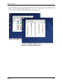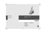
1
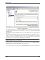
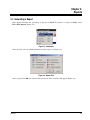
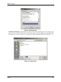
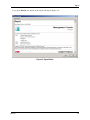
Simucad Management Console
(SMAN)
User’s Manual
SIMUCAD
4701 Patrick Henry Drive, Bldg. 2
Santa Clara, CA 95054
Telephone
(408) 567-1000
FAX:
(408) 496-6080
Internet:
www.simucad.com
October 17, 2007
Simucad Management Console (SMAN)
User’s Manual
Copyright 2007
Simucad
4701 Patrick Henry Drive, Building #2
Santa Clara, CA 95054
Phone:
ii
(408) 567-1000
Simucad
Notice
The information contained in this document is subject to change without notice.
Simucad Design Automation, Inc. MAKES NO WARRANTY OF ANY KIND WITH REGARD
TO THIS MATERIAL, INCLUDING, BUT NOT LIMITED TO, THE IMPLIED WARRANTY OF
FITNESS FOR A PARTICULAR PURPOSE.
Simucad Design Automation, Inc. shall not be liable for errors contained herein, or for incidental or
consequential damages in connection with the furnishing, performance, or use of this material. This
document contains proprietary information, which is protected by copyright. All rights are reserved.
No part of this document may be photocopied, reproduced, or translated into another language without
the prior written consent of Simucad Design Automation, Inc.
GUARDIAN, GUARDIAN DRC, REALTIME DRC, GUARDIAN LVS, GUARDIAN LPE, EXPERT, EXPERTVIEWS,
GATEWAY, HARMONY, SMARTSPICE, SMARTSPICERF, SMARTSPICESEE, SMARTVIEW, SMARTLIB, SDDL,
TWISTER, SPRINT, HARMONY, SILOS, HYPERFAULT, TURBOLINT, LISA, QUEST, EXACT, CLEVER,
STELLAR, HIPEX-C, HIPEX-CRC, HIPEX-NET, HIPEX-RC, NOMAD, SCOUT, EDA OMNI, UTMOST,
UTMOST III, UTMOST IV, SPAYN, ACCUCELL, ACCUCORE, ACCUMODEL, ACCUTEST, SFLM, VYPER,
INTERPRETER, DECKBUILD, SMARTLIB, CIRCUIT OPTIMIZER, PROMOST, RESILIANCE, DISCOVERY,
ANALOG EXPRESS, ANALOG IC DESIGN FLOW, CELEBRITY, CELEBRITY_C++ are trademarks of
Simucad Design Automation, Inc.
© 2007 by Simucad Design Automation, Inc.
All other trademarks mentioned in this manual are the property of their respective owners.
Simucad
iii
How to Read this Manual
Style Conventions
Font Style/Convention
Description
Example
•
This represents a list of items or
terms.
•
Bullet A
•
Bullet B
•
Bullet C
1.
This represents a set of
directions to perform an action.
2.
3.
To open a door:
1. Unlock the door by inserting
the key into keyhole.
2. Turn key counter-clockwise.
3. Pull out the key from the
keyhole.
4. Grab the doorknob and turn
clockwise and pull.
→
This represents a sequence of
menu options and GUI buttons
to perform an action.
File→Open
Courier
This represents the commands,
parameters,
and
variables
syntax.
HAPPY BIRTHDAY
New Century Schoolbook
Bold
This represents the menu
options and buttons in the GUI.
File
New Century
Italics
This represents the equations.
abc=xyz
Schoolbook
Note:
This represents the additional
important information.
NEW CENTURY SCHOOLBOOK
IN SMALL CAPS
This represents the names of
the Simucad product names.
Simucad
Note: Make sure you save often when
working on a manual.
EXPERT,
GATEWAY, HIPEX,
SMARTSPICE, STELLAR, AND
UTMOST.
iv
Table of Contents
Chapter 1
Introduction . . . . . . . . . . . . . . . . . . . . . . . . . . . . . . . . . . . . . . . . . . . . . . . . . . . . . . . . . . . . . . 1-1
1.1: What is the Simucad Management Console . . . . . . . . . . . . . . . . . . . . . . . . . . . . . . . . . . . . . . . . . . . . . . . . . .
1.2: The SMAN Window . . . . . . . . . . . . . . . . . . . . . . . . . . . . . . . . . . . . . . . . . . . . . . . . . . . . . . . . . . . . . . . . . . . . . .
1.2.1: Running SMAN in Windows . . . . . . . . . . . . . . . . . . . . . . . . . . . . . . . . . . . . . . . . . . . . . . . . . . . . . . . . . . . .
1.2.2: Running SMAN in UNIX/Linux . . . . . . . . . . . . . . . . . . . . . . . . . . . . . . . . . . . . . . . . . . . . . . . . . . . . . . . . . .
1-1
1-2
1-2
1-2
Chapter 2
Actions. . . . . . . . . . . . . . . . . . . . . . . . . . . . . . . . . . . . . . . . . . . . . . . . . . . . . . . . . . . . . . . . . . 2-1
2.1: About Screen . . . . . . . . . . . . . . . . . . . . . . . . . . . . . . . . . . . . . . . . . . . . . . . . . . . . . . . . . . . . . . . . . . . . . . . . . . . 2-1
2.2: Documents Screen . . . . . . . . . . . . . . . . . . . . . . . . . . . . . . . . . . . . . . . . . . . . . . . . . . . . . . . . . . . . . . . . . . . . . . 2-2
2.3: Products Screen . . . . . . . . . . . . . . . . . . . . . . . . . . . . . . . . . . . . . . . . . . . . . . . . . . . . . . . . . . . . . . . . . . . . . . . . 2-5
2.3.1: TCAD Screen . . . . . . . . . . . . . . . . . . . . . . . . . . . . . . . . . . . . . . . . . . . . . . . . . . . . . . . . . . . . . . . . . . . . . . 2-6
2.3.2: Analog & Mixed Signal Screen . . . . . . . . . . . . . . . . . . . . . . . . . . . . . . . . . . . . . . . . . . . . . . . . . . . . . . . . . . 2-7
2.3.3: Custom IC CAD Screen . . . . . . . . . . . . . . . . . . . . . . . . . . . . . . . . . . . . . . . . . . . . . . . . . . . . . . . . . . . . . . . 2-8
2.3.4: Parasitic Extraction Screen . . . . . . . . . . . . . . . . . . . . . . . . . . . . . . . . . . . . . . . . . . . . . . . . . . . . . . . . . . . . 2-9
2.3.5: Logic Verification Screen . . . . . . . . . . . . . . . . . . . . . . . . . . . . . . . . . . . . . . . . . . . . . . . . . . . . . . . . . . . . . 2-10
2.3.6: Add and Manage Updates Screen . . . . . . . . . . . . . . . . . . . . . . . . . . . . . . . . . . . . . . . . . . . . . . . . . . . . . . 2-11
2.3.7: Utilities/Other Screen . . . . . . . . . . . . . . . . . . . . . . . . . . . . . . . . . . . . . . . . . . . . . . . . . . . . . . . . . . . . . . . . 2-12
2.4: System Screen . . . . . . . . . . . . . . . . . . . . . . . . . . . . . . . . . . . . . . . . . . . . . . . . . . . . . . . . . . . . . . . . . . . . . . . . . 2-13
2.4.1: System Information . . . . . . . . . . . . . . . . . . . . . . . . . . . . . . . . . . . . . . . . . . . . . . . . . . . . . . . . . . . . . . . . . 2-13
2.4.2: Communications Information . . . . . . . . . . . . . . . . . . . . . . . . . . . . . . . . . . . . . . . . . . . . . . . . . . . . . . . . . . 2-14
2.4.3: Environment Information . . . . . . . . . . . . . . . . . . . . . . . . . . . . . . . . . . . . . . . . . . . . . . . . . . . . . . . . . . . . . 2-15
2.4.4: Licensing Information . . . . . . . . . . . . . . . . . . . . . . . . . . . . . . . . . . . . . . . . . . . . . . . . . . . . . . . . . . . . . . . . 2-16
2.4.5: Processes Information . . . . . . . . . . . . . . . . . . . . . . . . . . . . . . . . . . . . . . . . . . . . . . . . . . . . . . . . . . . . . . . 2-18
2.5: Simucad Model Library Screen . . . . . . . . . . . . . . . . . . . . . . . . . . . . . . . . . . . . . . . . . . . . . . . . . . . . . . . . . . . 2-19
2.5.1: Site Configuration . . . . . . . . . . . . . . . . . . . . . . . . . . . . . . . . . . . . . . . . . . . . . . . . . . . . . . . . . . . . . . . . . . . 2-19
2.5.2: User Configuration . . . . . . . . . . . . . . . . . . . . . . . . . . . . . . . . . . . . . . . . . . . . . . . . . . . . . . . . . . . . . . . . . . 2-21
Chapter 3
Reports . . . . . . . . . . . . . . . . . . . . . . . . . . . . . . . . . . . . . . . . . . . . . . . . . . . . . . . . . . . . . . . . . 3-1
3.1: Generating a Report . . . . . . . . . . . . . . . . . . . . . . . . . . . . . . . . . . . . . . . . . . . . . . . . . . . . . . . . . . . . . . . . . . . . . 3-1
Appendix A
Installing Updates . . . . . . . . . . . . . . . . . . . . . . . . . . . . . . . . . . . . . . . . . . . . . . . . . . . . . . . . . A-1
A.1: Updating Simucad Products . . . . . . . . . . . . . . . . . . . . . . . . . . . . . . . . . . . . . . . . . . . . . . . . . . . . . . . . . . . . . .
A.1.1: Step 1: Start the Simucad Management Console (SMAN). . . . . . . . . . . . . . . . . . . . . . . . . . . . . . . . . . . . .
A.1.2: Step 2: Select the Add and Manage Updates button () from the toolbar or from the Tools menu. . . . . . .
A.1.3: Step 3: The Updates Installed window lists all installed baselines and updates. . . . . . . . . . . . . . . . . . . . .
A.1.4: Step 4: Click on the Browse button and select the update (.ssu) or baseline (.exe, .tar.gz, .tgz) file
to install. . . . . . . . . . . . . . . . . . . . . . . . . . . . . . . . . . . . . . . . . . . . . . . . . . . . . . . . . . . . . . . . . . . . .
A.1.5: Step 5: Click the Install button. . . . . . . . . . . . . . . . . . . . . . . . . . . . . . . . . . . . . . . . . . . . . . . . . . . . . . . . . .
A.1.6: Step 6: The update or baseline will be installed and any installation output will be displayed in the
Output window. . . . . . . . . . . . . . . . . . . . . . . . . . . . . . . . . . . . . . . . . . . . . . . . . . . . . . . . . . . . . . .
A.1.7: Step 7: A copy of all baseline and update files will be placed in the $Simucad\updates directory
(where $Simucad is the installation directory for Simucad products). . . . . . . . . . . . . . . . . . . . . .
Simucad
A-1
A-1
A-1
A-1
A-2
A-2
A-3
A-3
v
SMAN User’s Manual
Appendix B
Shortcuts. . . . . . . . . . . . . . . . . . . . . . . . . . . . . . . . . . . . . . . . . . . . . . . . . . . . . . . . . . . . . . . . B-1
B.1: Updating Shortcuts . . . . . . . . . . . . . . . . . . . . . . . . . . . . . . . . . . . . . . . . . . . . . . . . . . . . . . . . . . . . . . . . . . . . . B-1
B.2: Managing Shortcuts. . . . . . . . . . . . . . . . . . . . . . . . . . . . . . . . . . . . . . . . . . . . . . . . . . . . . . . . . . . . . . . . . . . . . B-3
vi
Simucad
Chapter 1:
Introduction
1.1: What is the Simucad Management Console
The Simucad Management Console (SMAN) is a tool used primarily for diagnostics and to provide
support engineers with all the necessary information for fixing a Simucad installation.
SMAN is available on multiple operating systems, including Windows, Solaris, Linux and HP-UX.
SMAN can act as a first line support tool for common setup problems and reference information. The
tool has the ability to query but is not limited to such information as memory usage, processor
information, machine architecture, communications information, and licensing.
This manual will describe the common uses of the SMAN tool and how to provide a report to Simucad
support staff to help them diagnose any problems faced.
Simucad
1-1
SMAN User’s Manual
1.2: The SMAN Window
1.2.1: Running SMAN in Windows
To run the latest version of SMAN, double-click the shortcut or select it from the Start Menu. The
SMAN Window will appear as shown in Figure 1-1. The SMAN Window has six main areas: Menu
Tool Bar, Action Window, Output Window, Status Bar and Copyright Window.
The Action Window is where you choose and perform actions. The Output Window contains output
for each of the actions. In some cases, further input is required, which is entered in the Output
Window. The Menu and Tool Bar windows simply allow quick access to some of the actions. The
Status Bar provides a summary of the current action. The Copyright Window displays the
copyright information of the program.
Figure 1-1: The SMAN Window
1.2.2: Running SMAN in UNIX/Linux
To run the latest version of SMAN, run the program from $SIMUCAD/bin/sman where $SIMUCAD
is the installation directory.
Simucad
1-2
Chapter 2:
Actions
2.1: About Screen
The About screen (Figure 2-1) shows the following information about the program, version number,
support details and copyright information. To open this screen, select Help→About.
Figure 2-1: About Screen
Simucad
2-1
SMAN User’s Manual
2.2: Documents Screen
The Documents Screen (Figure 2-2) shows you the documents that are installed in the Simucad
installation directory. These documents include manuals, release notes and support documents.
Figure 2-2: Documents Screen
The Documents output (Figure 2-3) is split into three sections:
•
specific product and application documentation
•
PDK documentation
•
document collections
Simucad
2-2
Actions
Figure 2-3: Product and Application Documents
Document collections (Figure 2-4) are documents that fall into the same category (e.g., the
Celebrity documentation).
Figure 2-4: Document Collections
Simucad
2-3
SMAN User’s Manual
PDK documents (Figure 2-5) are documents that contain the description and release notes of the
PDK collections installed.
Figure 2-5: PDK Documents
Simucad
2-4
Actions
2.3: Products Screen
The Products screen shows all the installed products in the current Simucad installation and
allows you to add and manage new updates received from Simucad. The main Products screen
(Figure 2-6) groups the products into their natural collections/packages.
Figure 2-6: Products Screen
The natural groupings of the products in collections/packages are the following groups:
•
TCAD
•
Analog & Mixed Signal
•
Custom IC CAD
•
Parasitic Extraction
•
Logic Verification
In addition to these groups, there are two more options available:
•
Add and Manage Updates
•
Utilities/Other
Simucad
2-5
SMAN User’s Manual
The following sections describe each of these groups.
2.3.1: TCAD Screen
The TCAD screen (Figure 2-7) details all the products that fall into the TCAD package. The TCAD
package is defined as “Simucad TCAD tools start with understanding the physics of the basic
semiconductor, dielectric, and conducting materials.”
Figure 2-7: TCAD Screen
The following products are in the TCAD package:
•
VWF: The integrated environment for TCAD software.
•
ATHENA: Develops and optimize semiconductor-manufacturing processes.
•
ATLAS: Simulates the electrical, optical, and thermal behavior of semiconductor devices.
•
MERCURY: The MESFET and HEMT simulation framework that contains:
• FASTBLAZE
• FASTNOISE
• FASTDEVEDIT
• MOCASIM
Simucad
2-6
Actions
2.3.2: Analog & Mixed Signal Screen
The Analog & Mixed Signal screen (Figure 2-8) details all the products that fall into the Analog &
Mixed Signal (AMS) package. The AMS package includes tools that allow you to perform design,
simulation and model extraction services.
Figure 2-8: Analog & Mixed Signal Screen
The following products are in the AMS package:
•
UTMOST III: This tool performs data acquisition, device characterization, parameter extraction, and model verification.
•
UTMOST IV: UTMOST IV Optimization Module provides an easy to use database-driven
environment to generate accurate high quality SPICE models and macro-models for analog,
mixed-signal, and RF applications.
•
TWISTER: Twister Full-Chip Hierarchical Analog Circuit Simulator can run 100M+ transistor
circuits, achieving 10X to 100X speedup vs. traditional flat SPICE simulators, without the use
of table-lookup models that cause accuracy and convergence problems typical for "fast-SPICE"
simulators.
•
SPAYN: This is the ideal statistical modeling tool for analyzing variances from model parameter extraction sequences, electrical test routines, and circuit test measurements.
•
GATEWAY: Schematic capture tool.
•
HARMONY: Analog/Mixed-Signal Simulator.
•
SMARTSPICE: Analog Circuit Simulator.
•
SMARTSPICE-RF: Harmonic Balance based Simulator.
•
SMARTSPICE-SEE: Integrated Single Event Effects Simulator.
•
Verilog-A: Verilog-A simulator.
Simucad
2-7
SMAN User’s Manual
2.3.3: Custom IC CAD Screen
The Custom IC CAD screen (Figure 2-9) details all the products that fall into the Custom IC CAD
package. This package includes tools that allows you to perform layout and LVS.
Figure 2-9: Custom IC CAD Screen
The following products are in the Custom IC CAD package:
•
EXPERT: The Layout Editor
•
GUARDIAN DRC/LVS/LPE: The Design Rule Checker, Layout Vs. Schematic and Layout Parameter Extraction tool.
Simucad
2-8
Actions
2.3.4: Parasitic Extraction Screen
The Parasitic Extraction screen (Figure 2-10) details all the products that fall into the Parasitic
Extraction package. This package includes tools that allow you to perform 2D and 3D parasitic
extraction, and 2D and 3D field solving.
Figure 2-10: Parasitic Extraction Screen
The following products are in the Parasitic Extraction package:
•
EXACT: 3D field solver.
•
QUEST: Calculates 3D frequency dependent inductance, resistance, capacitance and capacitive
loss for any multi-port network for RF SPICE analysis.
•
CLEVER: Physics-Based Parasitic Extractor.
•
STELLAR: Standard cell parasitic characterization.
•
HIPEX: Full-Chip Parasitic Extractor.
Simucad
2-9
SMAN User’s Manual
2.3.5: Logic Verification Screen
The Logic Verification screen (Figure 2-11) details all the products that fall into the Logic
Verification package. This package includes tools that allow you to perform digital simulations and
verification of digital simulations.
Figure 2-11: Logic Verification Screen
The following products are in the Logic Verification package:
•
SILOS: Verilog Simulator
•
TURBOLINT: Programmable HDL Checker
•
HYPERFAULT: Mixed Level Fault Simulator
Simucad
2-10
Actions
2.3.6: Add and Manage Updates Screen
The Add and Manage Updates screen (Figure 2-12) allows you to install and view installed
updates that were placed in the Simucad installation directory. For more information on Installing
Updates, see Appendix A: “Installing Updates”.
Figure 2-12: Add and Manage Updates Screen
The Updates Installed area informs you what updates are currently installed in the Simucad
installation directory.
The Output area will display the progress of the updates.
Simucad
2-11
SMAN User’s Manual
2.3.7: Utilities/Other Screen
The Utilties/Other screen (Figure 2-13) details all the Simucad products, including products that
do not fall into a specific category and utility programs that other products use.
Figure 2-13: Utilties/Other Screen
Simucad
2-12
Actions
2.4: System Screen
The System Screen of the SMAN product is used to diagnose any specific problem on the current
system and will check whether licensing and communications are available for the current
machine.
The System Screen is split up into the following sections:
•
System Information
•
Communications
•
Environment
•
Licensing
•
Processes
2.4.1: System Information
The System Information screen (Figure 2-14) returns all the important information about the
system, such as Operating System, Version, Name, Processor Information, User
Information and Memory Information.
Figure 2-14: System Information Screen
Simucad
2-13
SMAN User’s Manual
2.4.2: Communications Information
The Communications Information screen (Figure 2-15) shows the communications information for
Simucad products. It contains the name of the communications server used, whether the server is
local, and the currently running Simucad products that are using Communications and the
Security file.
The Security file is used to limit what products can be started by another Simucad product a ‘+’
allows full access.
The Communications Information screen also contains the diagnostics of the communications
through the Simucad communications library SIPC (Simucad Inter-Process Communications).
Figure 2-15: Communications Screen
Simucad
2-14
Actions
2.4.3: Environment Information
The Environment Information screen (Figure 2-16) shows all of the environment variables set for
Simucad products and all the environment variables set by the system.
Figure 2-16: Environment Screen
Simucad
2-15
SMAN User’s Manual
2.4.4: Licensing Information
The Licensing Information screen (Figure 2-17) shows the licensing environment setup on this
machine and informs you the status of the license monitor.
Figure 2-17: Licensing Screen
From the SMAN product, you can also manage the licensing server. On Windows, this is done
through the SMAN product itself (see Figure 2-18). On UNIX machines, SMAN asks you to enter
the name of the web browser to use to manage SFLM.
The License Management screen (Figure 2-18) shows the Active User(s), Valid Licenses and
gives you the ability to Install New License(s). Please see the SFLM USER’S MANUAL for more
details on licensing.
Simucad
2-16
Actions
Figure 2-18: License Management Screen
Simucad
2-17
SMAN User’s Manual
2.4.5: Processes Information
The Processes Information screen (Figure 2-19) displays all the processes that are currently
running on the machine (on Windows it will also display a list of all the services).
Figure 2-19: Processes Screen
Simucad
2-18
Actions
2.5: Simucad Model Library Screen
The Simucad Model Library (MODELLIB) Screen (Figure 2-20) allows you to configure each of the
model library enabled products. The configuration is divided into three sections the Default, Site
and User.
The Default configuration contains a list of the default models that are loaded by the model
library enabled products. The Default configuration, however, cannot be edited or modified in any
way. You can override the default models or add custom user models by changing or overriding the
default configuration for the entire site or for an individual user.
Figure 2-20: ModelLib Screen
2.5.1: Site Configuration
The Site configuration (Figure 2-21) allows you to specify the models that will be applied to all
users that run a MODELLIB enabled product from this installation directory. The configuration file
is placed in <S_INSTALL_ROOT>/var/slconfig where <S_INSTALL_ROOT> is the root directory
where the product have been installed (i.e., c:\sedatools).
To manage the site configuration, first select the Site tab in the screen and then select the product
to be configured. The list of model library enabled products is controlled by the Product combobox. Once you select the product, the list of available versions to configure will appear in the
Version combo-box. The list of available platforms to configure will then appear in the Platform
combo-box. If you installed the products to a platform specific folder, then only the platform
available will be shown.
Simucad
2-19
SMAN User’s Manual
Figure 2-21: Site Configuration
If no Site configuration exists, you will be prompted to copy one from the default configuration.
The starting configuration can also be regenerated at a later date by pressing the Copy from
Default button.
Once the Site tab contains model libraries, you can either modify or choose to add custom user
libraries.
To modify an existing library, change the collection that it is pointing to (each collection refers to a
different version of the MODELLIB libraries, which contain the default libraries released by
SIMUCAD) or change the model file that it is using. You can only pick model files compatible with
the model type (i.e., you cannot choose a BSIM model for a TFT model).
Note: Changing the collection is not recommended. You should always choose models from the same collection as the
default where possible. Not doing so may cause instability.
Alternatively, you can add, edit or delete a custom user library by pressing the Add User Library,
Edit User Library or Delete User Library buttons respectively.
When adding or editing a custom user library, the Model Details dialog (Figure 2-22) will appear.
Simucad
2-20
Actions
Figure 2-22: Custom User Library Details
You can only delete a custom user library. If you press the Delete User Library button while
selecting a default library, the action will be ignored.
Press the Save button once you are happy with the site configuration. This will create a site
configuration
file
in
the
<S_INSTALL_ROOT>/var/slconfig
directory,
where
<S_INSTALL_ROOT> is the root directory where the product have been installed (i.e.,
c:\sedatools).
To reset the site configuration, press the Remove button, which will remove the site configuration
file and clear the entries in SMAN.
2.5.2: User Configuration
The User configuration allows you to specify the models that a specific user will use when running
a specific version of a MODELLIB enabled product. The User configuration will override both the
default and site configurations. The configuration file is placed in <HOME>/slconfig where
<HOME> is the user’s home directory. On Windows, the home directory is determined by the
following:
1. Use the environment variable HOME.
2. Use the environment variable USERPROFILE.
3. Use the path formed by concatenating the HOMEDRIVE and HOMEPATH environment variables.
4. Use the environment variable SYSTEMDRIVE.
5. Default to C:\
To configure the models for a user, choose the product to be configured. The Product combo-box
controls the list of model library enabled products. Once you selected the product, the list of
available versions to configure will appear in the Version combo-box. The list of available
platforms to configure will then appear in the Platform combo-box. If you installed the products
to a platform specific folder, then only the platform available will be shown.
Simucad
2-21
SMAN User’s Manual
Figure 2-23: User Configuration
If no User configuration exists, you will be prompted to copy one from the default configuration or
site configuration. The starting configuration can also be regenerated at a later date by pressing
the Copy from Default or Copy from Site buttons.
Once the User tab contains model libraries, you can either modify or choose to add custom user
libraries.
To modify an existing library, change the collection that it is pointing to (each collection refers to a
different version of the MODELLIB libraries which contain the default libraries released by
Simucad), or change the model file that it is using. You can only pick model files compatible with
the model type (i.e., you cannot choose a BSIM model for a TFT model).
Note: Changing the collection is not recommended. You should always choose models from the same collection as the
default where possible. Not doing so may cause instability.
Alternatively, you can add, edit or delete a custom user library by pressing the Add User Library,
Edit User Library or Delete User Library buttons respectively.
When adding or editing a custom user library, the Model Details dialog (Figure 2-22) will appear.
You can only delete a custom user library. If you press the Delete User Library button while
selecting a default library, the action will be ignored.
Press the Save button once you are happy with the user configuration. This will create a user
configuration file in the <HOME>/slconfig directory, where <HOME> is the user’s home directory.
To reset the user configuration, press the Remove button, which will remove the user
configuration file and clear the entries in SMAN.
Simucad
2-22
Chapter 3:
Reports
3.1: Generating a Report
This chapter describes the generating of reports in SMAN. To generate a report in SMAN, select
File→New Report (Figure 3-1).
Figure 3-1: New Report
Once selected, you can exclude information in the report (see Figure 3-2).
Figure 3-2: Report Filter
Once you press the OK, the report will be generated and a summary will appear (Figure 3-3).
Simucad
3-1
SMAN User’s Manual
Figure 3-3: Report Summary
The Report Summary will show the progress of the report generation. Once the progress bar
stops, you can save, show the details or cancel the report. If you press Save, the following dialog
will ask you for a name to choose to save the report under (report files end in the extension .rpt).
Figure 3-4: Saving a report
Simucad
3-2
Reports
If you press Details, the details of the report will appear (Figure 3-5).
Figure 3-5: Report Details
Simucad
3-3
SMAN User’s Manual
This page is intentionally left blank.
Simucad
3-4
Appendix A:
Installing Updates
A.1: Updating Simucad Products
The following section describes the steps to install updates for Simucad products.
A.1.1: Step 1: Start the Simucad Management Console (SMAN).
A.1.2: Step 2: Select the Add and Manage Updates button (
from the Tools menu.
) from the toolbar or
A.1.3: Step 3: The Updates Installed window lists all installed baselines and updates.
Simucad
A-1
SMAN User’s Manual
A.1.4: Step 4: Click on the Browse button and select the update (.ssu) or baseline
(.exe, .tar.gz, .tgz) file to install.
A.1.5: Step 5: Click the Install button.
Simucad
A-2
Installing Updates
A.1.6: Step 6: The update or baseline will be installed and any installation output will
be displayed in the Output window.
A.1.7: Step 7: A copy of all baseline and update files will be placed in the
$Simucad\updates directory (where $Simucad is the installation directory
for Simucad products).
Simucad
A-3
SMAN User’s Manual
This page is intentionally left blank.
Simucad
A-4
Appendix B:
Shortcuts
B.1: Updating Shortcuts
The following section describes the steps to update the shortcuts and how the Simucad Management
Console (SMAN) maintains the shortcuts.
On Linux and Windows, SMAN creates shortcuts to the products that you have installed.
On Windows, SMAN will create a desktop shortcut pointing to the Shortcuts directory
($S_INSTALL_ROOT/Shortcuts). The desktop shortcut will reflect this if the path to this directory is
contained on a shared directory or network drive. Also on Windows, the program menu will be created
with each version of the products. See Figure B-1.
Figure B-1: Windows Desktop
Simucad
B-1
SMAN User’s Manual
On Linux, SMAN will create a desktop folder. This will contain the shortcuts of each product. This
folder is created under the home directories $HOME/Desktop and $HOME/.gnome-desktop to
take into account the KDE and GNOME desktops. See Figure B-2.
Figure B-2: Linux Desktops (GNOME & KDE)
Simucad
B-2
Shortcuts
B.2: Managing Shortcuts
SMAN also manages the shortcuts by making sure that the shortcuts are up-to-date with the
installed versions. This check is performed every time SMAN starts. It does this by comparing the
date when the shortcuts were last updated and when the last baseline or package was installed. If
the dates are different, you will be prompted with the following question (Figure B-3).
Figure B-3: Update Shortcuts
If you answer Never to the above question, it means that you will not be prompted until the next
package is installed.
You can update the shortcuts manually by typing in the command-line option -shortcuts (i.e.,
sman -shortcuts) or by clicking the Update Shortcuts button on the Add/Manage Shortcuts
screen (Figure B-4).
Figure B-4: Add/Manage Shortcuts
Simucad
B-3
SMAN User’s Manual
This page is intentionally left blank.
Simucad
B-4