1
DLP™ PROJECTOR
MODEL
XD700U
WD720U
User Manual
XD700U
WD720U
This User Manual is important to you.
Please read it before using your projector.
Downloaded From projector-manual.com
CAUTION
RISK OF ELECTRIC SHOCK
DO NOT OPEN
CAUTION: TO REDUCE THE RISK OF ELECTRIC
SHOCK, DO NOT REMOVE COVER (OR BACK)
NO USER-SERVICEABLE PARTS INSIDE
REFER SERVICING TO QUALIFIED SERVICE
PERSONNEL.
The lightning flash with arrowhead symbol within an equilateral triangle is intended to alert
the user to the presence of uninsulated “dangerous voltage” within the product’s enclosure
that may be of sufficient magnitude to constitute a risk of electric shock.
The exclamation point within an equilateral triangle is intended to alert the user to the
presence of important operating and maintenance (servicing) instructions in the literature
accompanying the appliance.
WARNING:
TO PREVENT FIRE OR SHOCK HAZARD, DO NOT EXPOSE THIS APPLIANCE TO RAIN OR MOISTURE.
CAUTION:
TO PREVENT ELECTRIC SHOCK, DO NOT USE THIS (POLARIZED) PLUG WITH AN EXTENSION CORD,
RECEPTACLE OR OTHER OUTLET UNLESS THE BLADES CAN BE FULLY INSERTED TO PREVENT BLADE
EXPOSURE.
NOTE:
SINCE THIS PROJECTOR IS PLUGGABLE EQUIPMENT, THE SOCKET-OUTLET SHALL BE INSTALLED NEAR
THE EQUIPMENT AND SHALL BE EASILY ACCESSIBLE.
CAUTION
The attached power cord is to be used exclusively for
this product. Never use it for other products.
WARNING
Use the attached specified power supply cord. If
you use another power supply cord, it may cause
interference with radio and television reception.
This apparatus must be grounded.
DO NOT LOOK DIRECTLY INTO THE LENS WHEN
THE PROJECTOR IS IN THE POWER ON MODE.
EN-2
Downloaded From projector-manual.com
Contents
Important safeguards ........................................................................................................................4
Overview............................................................................................................................................6
Remote control ..................................................................................................................................8
Installation ........................................................................................................................................9
Basic connections ...........................................................................................................................12
Preparation .....................................................................................................................................15
Basic operation ...............................................................................................................................17
Menu operation ...............................................................................................................................21
Image adjustment ............................................................................................................................31
Network settings .............................................................................................................................34
Advanced display utilities ................................................................................................................39
Advanced features ..........................................................................................................................47
Lamp replacement ..........................................................................................................................51
Troubleshooting ...............................................................................................................................53
Indicators.........................................................................................................................................57
Specifications ..................................................................................................................................58
Trademark, Registered trademark
t .BDJOUPTIJTBSFHJTUFSFEUSBEFNBSLPG"QQMF*OD
t %-1%JHJUBM.JDSPNJSSPS%FWJDF%.%BOE#SJMMJBOU$PMPSBSFBMMUSBEFNBSLTPG5FYBT*OTUSVNFOUT
t )%.*UIF)%.*MPHPBOE)JHI%FmOJUJPO.VMUJNFEJB*OUFSGBDFBSFUSBEFNBSLTPSSFHJTUFSFEUSBEFNBSLTPG)%.*
Licensing LLC.
t .JDSPTPGU8JOEPXT8JOEPXT8JOEPXT918JOEPXT7JTUB8JOEPXTBOE*OUFSOFU&YQMPSFSBSF
registered trademarks, trademarks, or trade names of Microsoft Corporation in the U.S. and/or other countries.
t 5IFUSBEFNBSLPG1+-JOLJTUSBEFNBSLBQQMJFEGPSSFHJTUSBUJPOPSSFHJTUFSFEUSBEFNBSLJO+BQBOUIF6OJUFE4UBUFT
and other countries and areas.
t $SFTUSPO3PPN7JFX$POOFDUFEJTBUSBEFNBSLPG$SFTUSPO&MFDUSPOJDT*OD
t 0UIFSCSBOEPSQSPEVDUOBNFTBSFUSBEFNBSLTPSSFHJTUFSFEUSBEFNBSLTPGUIFJSSFTQFDUJWFIPMEFST
EN-3
Downloaded From projector-manual.com
Important safeguards
1PXFSTPVSDFT
This projector should be operated only from the
type of power source indicated on the marking
label. If you are not sure of the type of power,
please consult your appliance dealer or local
power company.
11. Power-cord protection
Power-supply cords should be routed so that
they are not likely to be walked on or pinched
by items placed upon or against them. Pay
particular attention to cords at plugs, convenience
receptacles, and points where they exit from the
appliance. Do not put the power cord under a
carpet.
12. Overloading
Do not overload wall outlets and extension cords
as this can result in a fire or electric shock.
13. Objects and liquids
Never push objects of any kind through openings
of this projector as they may touch dangerous
voltage points or short-out parts that could result
in a fire or electric shock. Never spill liquid of any
kind on the projector.
14. Servicing
Do not attempt to service this projector by yourself.
Refer all servicing to qualified service personnel.
15. Damage requiring service
Unplug this projector from the wall outlet and refer
servicing to qualified service personnel under the
following conditions:
(a) If the power-supply cord or plug is damaged.
(b) If liquid has been spilled, or objects have fallen
into the projector.
(c) If the projector does not operate normally after
you follow the operating instructions. Adjust
only those controls that are covered by the
operating instructions. An improper adjustment
of other controls may result in damage and
may often require extensive work by a qualified
technician to restore the projector to its normal
operation.
(d) If the projector has been exposed to rain or
water.
(e) If the projector has been dropped or the
cabinet has been damaged.
(f) If the projector exhibits a distinct change in
performance - this indicates a need for service.
16. Replacement parts
When replacement parts are required, be sure
that the service technician has used replacement
parts specified by the manufacturer or parts
having the same characteristics as the original
part. Unauthorized substitutions may result in fire,
electric shock or other hazards.
17. Safety check
Upon completion of any service or repair to this
projector, ask the service technician to perform
safety checks determining that the projector is in a
safe operating condition.
Please read all these instructions regarding your
projector and retain them for future reference. Follow
all warnings and instructions marked on the projector.
1. Read instructions
All the safety and operating instructions should be
read before the appliance is operated.
2. Retain instructions
The safety and operating instructions should be
retained for future reference.
3. Warnings
All warnings on the appliance and in the operating
instructions should be adhered to.
4. Instructions
All operating instructions must be followed.
5. Cleaning
Unplug this projector from the wall outlet before
cleaning it. Do not use liquid aerosol cleaners. Use
a damp soft cloth for cleaning.
6. Attachments and equipment
Never add any attachments and/or equipment
without the approval of the manufacturer as such
additions may result in the risk of fire, electric
shock or other personal injury.
7. Water and moisture
Do not use this projector near water or in contact
with water.
8. Accessories
Do not place this projector on an unstable cart,
stand, tripod, bracket or table. Use only with a
cart, stand, tripod bracket, or table recommended
by the manufacturer or sold with the projector.
Any mounting of the appliance should follow
the manufacturer’s instructions and should use
a mounting accessory recommended by the
manufacturer.
An appliance and cart combination should be
moved with care. Quick stops, excessive force and
uneven surfaces may cause the appliance and cart
combination to overturn.
9. Ventilation
Slots and openings in the cabinet are provided
for ventilation, ensuring reliable operation of the
projector and to protect it from overheating. Do
not block these openings or allow them to be
blocked by placing the projector on a bed, sofa,
rug, or bookcase. Ensure that there is adequate
ventilation and that the manufacturer’s instructions
have been adhered to.
EN-4
Downloaded From projector-manual.com
Important safeguards (continued)
Do not use the projector with condensation on it.
It can lead to breakdown or other failure.
WARNING:
Unplug immediately if there is something wrong
with your projector.
Do not operate if smoke, strange noise or odor comes
out of your projector. It may cause fire or electric
shock. In this case, unplug immediately and contact
your dealer.
Place of installation
For safety’s sake, do not use the projector at any place
subjected to high temperature and high humidity.
Please maintain an operating temperature, humidity,
and altitude as specified below.
t 0QFSBUJOHUFNQFSBUVSFCFUXFFO¡'¡$
BOE
¡'¡$
t 0QFSBUJOHIVNJEJUZCFUXFFOBOE
t /FWFSQVUBOZIFBUQSPEVDJOHEFWJDFVOEFSUIF
projector to prevent the projector from being
overheated.
t %POPUJOTUBMMUIFQSPKFDUPSBUBQMBDFUIBUJT
unstable or subject to vibration.
t %POPUJOTUBMMUIFQSPKFDUPSOFBSBOZFRVJQNFOUUIBU
produces a strong magnetic field. Also refrain from
installing the projector near any cable carrying a
large amount of current.
t 1MBDFUIFQSPKFDUPSPOBTPMJEWJCSBUJPOGSFF
surface. Otherwise it may fall, causing serious injury
or damage.
t %POPUTUBOEUIFQSPKFDUPSPOJUTFOE*UNBZGBMM
causing serious injury or damage.
t 4MBOUJOHUIFQSPKFDUPSNPSFUIBO¡SJHIUBOE
MFGU
PS¡GSPOUBOESFBS
NBZDBVTFUSPVCMFPS
explosion of the lamp.
t %POPUQMBDFUIFQSPKFDUPSOFBSBJSDPOEJUJPOJOH
unit, heater, or humidifier to avoid hot or moist air
to the exhaust and ventilation hole of the projector.
t Do not place the projector in the following places.
Otherwise, a short circuit, heat generation, or melting
of the power cord coating may occur, causing fire,
electric shock, product failure, or deformation.
t 0VUEPPSTPSOPOBJSDPOEJUJPOFEQMBDF
t 1MBDFXIFSFBHBTTVDIBTBIZESPHFOTVMmEFJT
generated (i.e. hot spring)
t 1MBDFXIFSFUIFSFJTUPPNVDITBMUTVDIBTOFBS
the coast
t #FTVSFUPVTFUIJTQSPKFDUPSBUBOBMUJUVEFPGMFTT
UIBONFUFST
Never remove the cabinet.
This projector contains high voltage circuitry. An
inadvertent contact may result in an electric shock.
Except as specifically explained in User Manual, do
not attempt to service this product by yourself. Please
contact your dealer when you want to fix, adjust, or
inspect the projector.
Do not modify this equipment.
It can lead to fire or electric shock.
Do not keep using the damaged projector.
If the projector is dropped and the cabinet is
damaged, unplug the projector and contact your
dealer for inspection. It may lead to fire if you keep
using the damaged projector.
Be sure to unplug the power cord from the wall
outlet if the projector is fractured or deformed.
Otherwise, it may result in fire or electric shock. Ask
your dealer for repair.
Do not face the projector lens to the sun.
It can lead to fire.
Use correct voltage.
If you use incorrect voltage, it can lead to fire.
Do not place the projector on uneven surface.
Place the projection on a leveled and stable surface only.
Do not look into the lens when it is operating.
It may hurt your eyes. Never let children look into the
lens when it is on.
Do not put any objects immediately in front of the
lens while the lamp is on.
The lens and the objects get hot and can cause fire or
breakdown.
Do not place a container containing water or other
liquid on the projector.
If water spills on or enters the projector, it may result in
fire or electric shock.
Do not unplug the power cord during operation.
It can lead to lamp breakage, fire, electric shock or
other trouble.
Do not put any object that is heavy or larger than
the outer frame on the projector.
Otherwise, the object may fall losing its balance and
cause injury.
Do not touch the exhaust vents and bottom plate.
Do not touch them or put other equipment close to
the exhaust vents because they become hot during
operation. The heated exhaust vents and bottom
plate may cause injury or damage to other equipment.
Also, do not put the projector on a desk that is easily
affected by heat.
Do not subject the projector to strong shocks or
vibrations. Do not handle the projector roughly.
The projector may be damaged, resulting in fire or
electric shock.
Do not look into the exhaust vents when projector
is operating.
Heat, dust, etc. may blow out of them and hurt your eyes.
When removing the lamp from the ceiling-mounted
projector
Be sure to use the lamp replacement attachment
designed specifically for this projector when replacing
the lamp with a new one. Lamp fragments may fall
from the inside if the lamp were broken.
Do not block the intake and exhaust vents.
If they are blocked, heat may be generated inside the projector,
causing deterioration in the projector quality and fire.
Do not use flammable solvents (benzene, thinner,
etc.) and flammable aerosols near the projector.
Flammable substances may ignite causing fire or
breakdown because the temperature inside the
projector rises very high while the lamp is illuminating.
EN-5
Downloaded From projector-manual.com
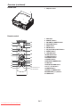
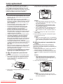
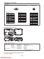
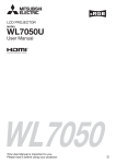
Overview
1
2
3
4
5
6
789
10
12
13
11
1
2
3
4
5
6
7
8
9
10
11
12
13
14
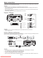
Lamp cover
Lens
FOCUS ring
ZOOM ring
LENS SHIFT dial
Remote control sensor (front)
Speaker
Lock bar
Intake vent
Control panel
Exhaust vent
Power jack
Terminal panel
Kensington Lock
Caution:
t %POPUSFQMBDFUIFMBNQJNNFEJBUFMZBGUFSVTJOHUIF
projector because the lamp would be extremely hot
and it may cause burns.
14
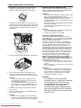
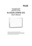
Control panel
1
5
2
6
7
8
3
4
9
10
1
2
3
4
5
6
7
8
9
10
AUTO POSITION/ button
EFFICIENT MODE button
STATUS indicator
POWER indicator
COMPUTER/ button
button
VIDEO/ button
KEYSTONE/ENTER button
MENU button
POWER button (ON/STANDBY)
The status is changed between ON and STANDBY.
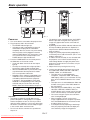
1
2
3
4
5
6
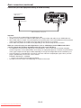
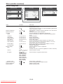
AUDIO OUT terminal (mini jack)
AUDIO IN-1 terminal (mini jack)
AUDIO IN-3 terminals (L, R)
S-VIDEO terminal
SERIAL (RS-232C) terminal (D-SUB 9-pin)
COMPUTER/COMPONENT VIDEO IN terminals (1, 2)
(mini D-SUB 15-pin)
HDMI terminal (HDMI 19-pin)
Remote control sensor (rear)
AUDIO IN-2 terminal (mini jack)
VIDEO terminal
MONITOR OUT terminal (mini D-SUB 15-pin)
USB-B terminal
USB-A terminal
LAN terminal (RJ-45)
Terminal panel
1
2 3
8 9
4
10
5
11
6
7
12 13 14
7
8
9
10
11
12
13
14
EN-6
Downloaded From projector-manual.com
Overview (continued)
Bottom side
1 Adjustment feet
1
Remote control
ON
STANDBY
MAGNIFY
ASPECT
12
1
13
14
2
3
VOL
UP EFFICIENT
MODE
DOWN
KEYSTONE
3D
15
4
AUTO
POSITION
MENU
5
6
16
ENTER
17
AV
MUTE
7
8
9
10
FREEZE
18
VIEWER
VIDEO
1
19
COMPUTER
UNPLUG
USB DISP.
S-VIDEO
2
LAN DISP.
11
DVI
HDMI
20
21
This model does not
have this function.
EN-7
Downloaded From projector-manual.com
1
2
3
4
5
6
7
8
9
10
11
12
13
14
15
16
17
18
19
20
21
ON button
MAGNIFY button
VOLUME UP, DOWN buttons
KEYSTONE button
MENU button
ENTER button
AV (Audio/Video) MUTE button
VIEWER button
UNPLUG button
USB DISP. button
LAN DISP. button
STANDBY button
ASPECT button
EFFICIENT MODE button
3D button
AUTO POSITION button
, , , buttons
FREEZE button
VIDEO, S-VIDEO buttons
COMPUTER (1, 2) buttons
HDMI button
Remote control
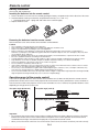
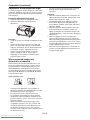
Battery installation
Use two (AA, R6) size batteries.
Inserting the batteries into the remote control
1. Remove the back cover of the remote control by pushing the battery compartment door in the direction of the arrow.
-PBEUIFCBUUFSJFTNBLJOHTVSFUIBUUIFZBSFQPTJUJPOFEDPSSFDUMZUPBOEUP
t -PBEUIFCBUUFSJFTGSPNTQSJOHTJEFBOENBLFTVSFUPTFUUIFNUJHIUMZ
3. Replace the back cover.
Removing the batteries from the remote control
Remove the back cover of the remote control and take out the batteries.
Caution:
t
t
t
t
t
t
t
t
t
t
t
t
t
6TFPGBCBUUFSZPGXSPOHUZQFNBZDBVTFFYQMPTJPO
0OMZ$BSCPO;JODPS"MLBMJOF.BOHBOFTF%JPYJEFUZQFCBUUFSJFTTIPVMECFVTFE
%JTQPTFPGVTFECBUUFSJFTBDDPSEJOHUPZPVSMPDBMSFHVMBUJPOT
#FGPSFZPVEJTQPTFPGUIFCBUUFSJFTJOTVMBUFUIFNCZQMBDJOHJOTVMBUJPOUBQFPOUIFQPTJUJWF
BOEOFHBUJWF
terminals. If you dispose of the batteries together with other conductive objects such as a metal piece, they may short
out, resulting in fire or explosion.
Batteries may explode if misused. Do not recharge, disassemble, or heat the batteries, or put them into fire or water.
#FTVSFUPIBOEMFUIFCBUUFSJFTBDDPSEJOHUPUIFJOTUSVDUJPOT
-PBEUIFCBUUFSJFTXJUIJUTQPTJUJWF
BOEOFHBUJWF
TJEFTDPSSFDUMZPSJFOUFEBTJOEJDBUFEPOUIFSFNPUFDPOUSPM
,FFQCBUUFSJFTPVUPGSFBDIPGDIJMESFOBOEQFUT*GDIJMESFOTXBMMPXUIFCBUUFSZTFFBEPDUPSJNNFEJBUFMZ
3FNPWFUIFCBUUFSJFTJGUIFSFNPUFDPOUSPMJTOPUVTFEGPSBMPOHUJNF
%POPUDPNCJOFBOFXCBUUFSZXJUIBOPMEPOF
*GUIFTPMVUJPOPGCBUUFSJFTDPNFTJODPOUBDUXJUIZPVSTLJOPSDMPUIFTSJOTFXJUIXBUFS*GUIFTPMVUJPODPNFTJODPOUBDU
with your eyes, rinse them with water and then consult your doctor.
%POPUDBSSZPSTUPSFUIFCBUUFSJFTUPHFUIFSXJUINFUBMMJDCBMMQPJOUQFOTOFDLMBDFTDPJOTPSIBJSQJOT0UIFSXJTFUIFZ
may short out, causing explosion or liquid leakage and resulting in fire or injury.
%POPUTUPSFUIFCBUUFSJFTXIFSFUIFZBSFFYQPTFEUPEJSFDUTVOMJHIUPSTVCKFDUFEUPIJHIUFNQFSBUVSFBOEIJHIIVNJEJUZ
High temperature and high humidity may cause corrosion or liquid leakage.
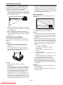
Operation range (of the remote control)
5IFNBYJNVNPQFSBUJPOEJTUBODFPGUIFSFNPUFDPOUSPMJTBCPVUNPSBCPVUGFFU
XIFOUIFSFNPUFDPOUSPMJT
pointed at the remote control sensor of the projector. When the remote control is pointed to the screen, the distance
from the remote control to the projector via the screen should be 5 m or less. However, the operation distance varies
depending on the type of the screen used.
Reception angle (horizontal)
Reception angle (vertical)
¡
¡
¡
¡
Reception angle (vertical), ceiling mount
¡
¡
¡
¡
Important:
t %POPUFYQPTFUIFSFNPUFDPOUSPMTFOTPSUPEJSFDUTVOMJHIUPSnVPSFTDFOU,FFQBEJTUBODFBUMFBTUNGFFU
between the remote control sensor and the fluorescent light to ensure correct operation of the remote control.
Inverted fluorescent light, if located near the projector, may interfere the remote control.
t When you use the remote control too close to the remote control sensor, the remote control may not work correctly.
EN-8
Downloaded From projector-manual.com
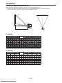
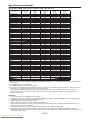
Installation
Screen size and projection distance
Refer to the following tables to determine the screen size and projection distance.
t 5IFmHVSFTJOUIFUBCMFTBSFBQQSPYJNBUFBOENBZCFTMJHIUMZEJGGFSFOUGSPNUIFBDUVBMNFBTVSFNFOUT
t 5IFMFOTTIJGUIFJHIUTIPXTEJTUBODFTGSPNUIFGBDUPSZEFGBVMUQPTJUJPO
Screen
Screen height (SH)
Screen width (SW)
H2 H1
Hd
Down side
Up side
L
For XD700U:
Screen size (4:3)
Diagonal size
inch
cm
152
254
381
635
762
Width (SW)
Height (SH)
inch
32
48
64
96
inch
24
36
48
72
cm
81
122
163
244
cm
61
91
122
152
183
229
381
457
Projection distance (L)
Hd
inch
3.6
5
7
9
11
14
18
23
27
Lens shift height
Shortest (Wide) Longest (Tele)
cm
9
14
18
23
27
34
46
57
69
inch
45
68
91
115
138
173
231
289
348
m
1.1
1.7
2.3
2.9
3.5
4.4
5.9
7.3
8.8
inch
67
137
171
258
344
-
m
1.7
2.6
3.5
4.3
5.2
6.5
8.7
-
H1
inch
3
4
5
7
8
13
17
H2
cm
7
14
17
25
34
42
51
inch
2
2
3
4
5
6
8
12
cm
4
6
8
13
16
21
26
31
For WD720U:
4DSFFOTJ[F
Diagonal size
Width (SW)
Height (SH)
inch
inch
34
51
68
85
127
212
254
inch
21
32
42
53
64
79
132
159
cm
152
254
381
635
762
cm
86
129
172
215
258
323
431
538
646
cm
54
81
135
162
269
337
Projection distance (L)
Hd
inch
6.2
9
12
15
18
23
31
38
46
cm
16
23
31
39
47
59
78
98
117
inch
49
74
125
188
251
314
377
m
1.2
1.9
2.5
3.2
3.8
4.8
6.4
9.6
inch
73
111
149
187
225
282
377
-
m
1.9
2.8
3.8
4.8
5.7
7.2
9.6
-
EN-9
Downloaded From projector-manual.com
Lens shift height
Shortest (Wide) Longest (Tele)
H1
inch
3
4
6
7
9
11
14
18
22
H2
cm
7
11
15
18
22
27
36
46
55
inch
3
4
5
6
8
9
13
16
19
cm
6
13
16
19
24
32
48
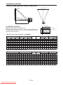
Installation (continued)
Screen size and projection distance (continued)
Screen
Screen height (SH)
Screen width (SW)
H2 H1
Hd
Down side
Up side
L
For WD720U: (continued)
B
SW (=W)
When the aspect ratio of the screen is 4:3
When the aspect ratio of the screen is 4:3, the positional relation between
the projected image and the screen is as shown on the right. Refer to the
following table for installation.
H
*NBHF
B
SH
Screen (4:3)
t8IFOUIFBTQFDUSBUJPPGUIFJNBHFJT89("
4J[FPGUIFQSPKFDUFEJNBHF
Black space
(B)
Width (W)
Height (H)
Screen size (4:3)
Diagonal size Width (SW)
inch
cm
152
254
381
635
762
inch
32
48
64
96
cm
81
122
163
244
Height (SH) Diagonal size
inch
24
36
48
72
cm
61
91
122
152
183
229
381
457
inch
38
57
75
94
113
142
189
236
283
cm
96
144
192
288
359
479
599
719
inch
32
48
64
96
cm
81
122
163
244
inch
75
125
cm
51
76
127
152
191
254
318
381
inch
2
3
4
5
6
8
13
15
cm
5
8
13
15
19
25
32
38
Hd
inch
6
9
12
15
17
22
29
36
44
cm
15
22
37
44
55
74
92
111
Projection distance (L)
Shortest (Wide) Longest (Tele)
inch
46
94
118
141
177
236
296
355
m
1.2
1.8
2.4
3.6
4.5
7.5
inch
69
141
177
212
266
356
-
m
1.8
2.7
3.6
4.5
5.4
6.8
-
Lens shift height
H1
inch
3
4
5
7
8
14
17
H2
cm
7
14
17
21
26
34
43
52
inch
2
4
5
6
7
9
12
15
18
cm
6
9
12
15
18
22
37
45
t8IFOUIFBTQFDUSBUJPPGUIFJNBHFJT
Screen size (4:3)
Diagonal size Width (SW)
inch
cm
152
254
381
635
762
inch
32
48
64
96
cm
81
122
163
244
Size of the projected image (16:9)
Height (SH) Diagonal size
inch
24
36
48
72
cm
61
91
122
152
183
229
381
457
inch
37
55
73
92
138
184
229
275
cm
93
187
233
466
583
699
Width (W)
inch
32
48
64
96
cm
81
122
163
244
Height (H)
Black space
(B)
inch
18
27
36
45
54
68
113
135
inch
3
5
6
8
9
11
15
19
23
cm
46
69
91
114
137
171
229
286
343
&/
Downloaded From projector-manual.com
cm
8
11
15
19
23
29
38
48
57
Hd
inch
7
14
17
26
34
43
51
cm
17
26
35
43
52
65
86
Projection distance (L)
Shortest (Wide) Longest (Tele)
inch
45
68
91
114
138
172
288
346
m
1.1
1.7
2.3
2.9
3.5
4.4
5.8
7.3
8.8
inch
67
137
172
259
346
-
m
1.7
2.6
3.5
4.4
5.2
6.6
8.8
-
Lens shift height
H1
inch
2
4
5
6
7
9
12
15
18
H2
cm
6
9
12
15
19
23
31
39
46
inch
2
3
4
5
6
8
11
13
16
cm
5
8
11
13
16
27
34
Installation (continued)
kit. (Don’t use screw holes without arrow marks.) In
this case, make sure that the screw is inserted in
the projector at least 5 mm. The length of the screw
TIPVMECFNNPSTIPSUFS"MTPNBLFTVSFUIBU
no electrical current is flowing in the mount kit due
to current leakage or other cause.
Front projection, ceiling mounting
For ceiling mounting, you need the ceiling mount
kit designed for this projector. Ask a specialist for
installation. For details, consult your dealer.
t 5IFXBSSBOUZPOUIJTQSPKFDUPSEPFTOPUDPWFSBOZ
damage caused by use of any non-recommended
ceiling mount kit or installation of the ceiling mount
kit in an improper location.
Rear projection
Ask a specialist for installation. For details, consult
your dealer.
t 8IFOVTJOHUIFQSPKFDUPSNPVOUFEPOUIFDFJMJOH
set Image Reverse in the Installation menu to Mirror
Invert. See page 27.
t 8IFOUIFQSPKFDUPSJTNPVOUFEPOUIFDFJMJOH
images may appear darker than those projected in
the case of tabletop mounting. This isn’t a product
malfunction.
t 'PSSFBSQSPKFDUJPOTFU*NBHF3FWFSTFJOUIF
Installation menu to Mirror. See page 27.
Caution:
t 1MBDJOHUIFQSPKFDUPSEJSFDUMZPOBDBSQFUJNQBJST
ventilation by the fans, causing damage or failure.
Put a hard board under the projector to facilitate
ventilation.
t 1MBDFUIFQSPKFDUPSBUMFBTUDNPSJODI
BXBZ
from the wall to prevent the intake vents and the
exhaust vents that emit hot air from being blocked.
t %POPUVTFUIFQSPKFDUPSJOUIFGPMMPXJOHMPDBUJPOT
and manners, which may cause fire or electric
shock.
t *OBEVTUZPSIVNJEQMBDF
t *OBTJEFXBZTPSVQTJEFEPXOQPTJUJPO
t /FBSBIFBUFS
t *OBOPJMZTNPLZPSEBNQQMBDFTVDIBTB
kitchen.
t *OEJSFDUTVOMJHIU
t 8IFSFUIFUFNQFSBUVSFSJTFTIJHITVDIBTJOB
closed car.
t 8IFSFUIFUFNQFSBUVSFJTMPXFSUIBO¡'PS
¡$
PSIJHIFSUIBO¡'PS¡$
t ,FFQGPMJBHFQMBOUTBOEQFUTBXBZGSPNUIF
projector. The temperature around the exhaust
vents and that of the cabinet on the top of the
exhaust vents become high. Take special care for
small children.
Ceiling mount installation
If you wish to install the projector using a ceiling
mount, please use the screw holes as the illustration
shows.
Important:
t 4DSFXTBSFOPUJODMVEFE1MFBTFPCUBJOUIF
appropriate screws for your type of ceiling. (M4
diameter)
t *UJTSFDPNNFOEFEUIBUZPVLFFQBSFBTPOBCMF
space between the bracket and the projector to
allow for proper heat distribution.
Caution:
t *OTUBMMBUJPONVTUCFEPOFCZBRVBMJmFE
professional.
When the projector is installed on the ceiling using
the ceiling mount kit, it is recommended to hold
the mount kit and the projector using a metal bar
or wire in addition to the mount kit fixing screws
to prevent the projector from falling due to an
earthquake or other cause. For that purpose, use
a metal bar, wire, or screw that bears a load of at
least 55 kgf. When using a metal wire, secure one
end to a screw hole marked with an arrow on the
rear terminal panel and the other end to the mount
Important:
t %POPUBQQMZGPSDFUPUIFMFOTCFDBVTFUIFMFOT
may be damaged.
t #FTVSFUPVTFUIJTQSPKFDUPSBUBOBMUJUVEFPGMFTT
UIBONFUFST
EN-11
Downloaded From projector-manual.com
Basic connections
This projector can be connected with various devices such as a VCR, video camera, videodisc player, and personal
computer that have analog RGB output connectors.
Important:
t .BLFTVSFUIBUUIFDPOOFDUFEEFWJDFJTUVSOFEPGGCFGPSFTUBSUJOHDPOOFDUJPO
t 1MVHJOUIFQPXFSDPSETPGUIFQSPKFDUPSBOEUIFDPOOFDUFEEFWJDFTmSNMZ8IFOVOQMVHHJOHIPMEBOEQVMMUIF
plug. Do not pull the cord.
t 8IFOUIFQSPKFDUPSBOEUIFDPOOFDUFEEFWJDFTBSFMPDBUFEUPPDMPTFUPFBDIPUIFSUIFQSPKFDUFEJNBHFNBZCF
affected by their interference.
t 4FFUIFPXOFSTHVJEFPGFBDIEFWJDFGPSEFUBJMTBCPVUJUTDPOOFDUJPOT
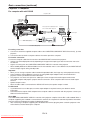
Projector + AV device
S-VIDEO
(option)
VIDEO
(option)
AUDIO IN-3L
(option)
AUDIO IN-3R
To audio output (L)
To audio output (R)
VCR, etc.
To video output
To S-Video output
Important:
t .BUDIUIFDPMPSTPGUIFWJEFPBOEBVEJPQMVHTPOUIF"VEJPDBCMFXJUIUIPTFPGUIFUFSNJOBMT
t 4QFBLFSPVUQVUJTNPOP
Projector + DVD player or HDTV decoder
Some DVD players have an output connector for 3-line fitting (Y, CB, CR). When connecting such DVD player with this
projector, use the COMPUTER/COMPONENT VIDEO IN terminal.
Audio cable (option)
DVD player or HDTV decoder
To audio output
BNC - RCA connector (option)
No connection
B
R
G
Mini D-SUB 15-pin - BNC
conversion cable (option)
COMPUTER/COMPONENT VIDEO IN
Important:
t 5IFUFSNJOBMTOBNFT:1B, and PR are given as examples of when a HDTV decoder is connected.
t 5IFUFSNJOBMTOBNFTWBSZEFQFOEJOHPOUIFDPOOFDUFEEFWJDFT
t 6TFBNJOJ%46#QJO#/$DPOWFSTJPODBCMFGPSDPOOFDUJPO
t *NBHFNBZOPUCFQSPKFDUFEDPSSFDUMZXJUITPNF%7%QMBZFST
t 8IFODPOOFDUJOHB)%57EFDPEFSIBWJOH3(#PVUQVUUFSNJOBMTTFU$PNQVUFS*OQVUUP3(#JOUIF4JHOBMNFOV
EN-12
Downloaded From projector-manual.com
Basic connections (continued)
Connection (for video equipment having an HDMI terminal)
Equipment having an
HDMI terminal
To HDMI terminal
HDMI
HDMI (with HDMI logo) cable (option)
Important:
t 6TFBDPNNFSDJBMMZBWBJMBCMF)%.*XJUI)%.*MPHP
DBCMF
t :PVEPOUIBWFUPDPOOFDUBOZDBCMFGPSBVEJPJOQVU:PVDBOJOQVUWJEFPBOEBVEJPVTJOHBO)%.*DBCMFPOMZ
t 8IFO)%.*BVEJPJTOUPVUQVUJUNBZCFPVUQVUCZUVSOJOHPGGUIFQPXFSPGUIFWJEFPFRVJQNFOUXJUIUIFQSPKFDUPS
and the video equipment connected to each other and then turning back on the power.
t 4PNFDBCMFTNBZOPUCFDPOOFDUFEDPSSFDUMZEFQFOEJOHPOUIFTJ[FBOETIBQFPGUIFJSDPOOFDUPST
When you connect this projector and a Digital device (such as a DVD player) via the HDMI terminal, black
color may appear dark and deep, depending on the type of the connected device.
t 5IJTEFQFOETPOUIFCMBDLMFWFMTFUUJOHPGUIFDPOOFDUFEEFWJDF5IFSFBSFUXPLJOETPGNFUIPETUPEJHJUBMMZ
transfer image data, in which different black level settings are employed respectively. Therefore, the specifications
of the signals output from DVD players differ, depending on the type of the digital data transfer method they use.
t 4PNF%7%QMBZFSTBSFQSPWJEFEXJUIBGVODUJPOUPTXJUDIUIFNFUIPETUPPVUQVUEJHJUBMTJHOBMT8IFOZPVS%7%
player is provided with such function, set it as follows.
EXPAND or ENHANCED NORMAL
t 4FFUIFVTFSTHVJEFPGZPVS%7%QMBZFSGPSEFUBJMT
t 4FU*OQVU-FWFMJOUIF1JDUVSFNFOVEFQFOEJOHPOUIFEFWJDFUPCFVTFE
EN-13
Downloaded From projector-manual.com
Basic connections (continued)
Projector + Computer
For computer with mini D-SUB
Computer cable
COMPUTER/
COMPONENT
VIDEO IN
Necessary when outputting to both
a PC monitor and the projector.
Computer
Computer cable (option)
To monitor port
MONITOR OUT
AUDIO
OUT
AUDIO IN-1
or IN-2
Audio cable (option)
PC audio cable (option)
To PC audio output
For analog connection:
1. Connect one end of the supplied computer cable to the COMPUTER/COMPONENT VIDEO IN terminal (1, 2) of the
projector.
2. Connect the other end of the computer cable to the monitor port of the computer.
For monitor connection:
Connect the computer cable from the monitor to the MONITOR OUT terminal of the projector.
t *NBHFTNBZOPUCFEJTQMBZFEDPSSFDUMZEFQFOEJOHPOUIFUZQFPGUIFJOQVUTJHOBM4FFUIFJOTUSVDUJPONBOVBMPG
the monitor.
t 4JHOBMTBSFDPNJOHGSPNUIF$0.165&3$0.10/&/57*%&0*/UFSNJOBMPGUIFQSPKFDUPS
t 8IFO4UBOECZ.PEFPGUIF&GmDJFOU.PEFNFOVJOUIF*OTUBMMBUJPONFOVJTTFUUP.POJUPS0VUUIF.0/*503065
terminal outputs signals during standby mode.
Important:
t 8IFOZPVVTFBMPOHFSDPNQVUFSDBCMFJOTUFBEPGUIFQSPWJEFEDBCMFUIFJNBHFNBZOPUCFQSPKFDUFEDPSSFDUMZ
t 4PNFDPNQVUFSTSFRVJSFBEEJUJPOBMDPOOFDUPSTPSBOBMPH3(#PVUQVUBEBQUFSTUPCFDPOOFDUFEXJUIUIJT
projector. Contact your dealer for further information.
t 5IJTQSPKFDUPSVTFTTUFSFPNJOJKBDLGPSJUTBVEJPJOQVU$IFDLUIFUZQFPGUIFBVEJPPVUQVUUFSNJOBMPGUIF
connected computer and prepare a proper cable for connection. Some computers don’t have the audio output
terminal.
t 4QFBLFSPVUQVUJTNPOP
t 8IFOUIFBVEJPDBCMFJTDPOOFDUFEUPUIF"6%*0065UFSNJOBMUIFTQFBLFSPVUQVUJTNVUFE
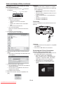
For Macintosh
t *GZPVS.BDJOUPTIIBTOPWJEFPQPSUBNPOJUPSPVUQVUBEBQUFSJTSFRVJSFE$POUBDUZPVSEFBMFSGPSGVSUIFS
information.
t 4PNF.BDJOUPTIFTSFRVJSFB."$BEBQUFSGPSUIFDPNQVUFSDBCMFGPSDPOOFDUJPOXJUIUIJTQSPKFDUPS$POUBDUZPVS
dealer for further information.
About DDC
The COMPUTER/COMPONENT VIDEO IN-1 terminal of this projector complies with the DDC 1/2B standard. When a
computer supporting this standard is connected to this terminal, the computer will automatically load the information
from this projector and prepare for output of appropriate images.
t "GUFSDPOOFDUJOHBDPNQVUFSTVQQPSUJOHUIJTTUBOEBSEUPUIJTUFSNJOBMQMVHUIFQPXFSDPSEPGUIFQSPKFDUPSJOUIF
wall outlet first, and then boot up the computer.
EN-14
Downloaded From projector-manual.com
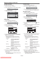
Preparation
Preparation for projection
1. Attach the provided power cord to the projector.
2. Plug the power cord in the wall outlet.
3. Remove the lens cap.
Warning:
t %POPUMPPLJOUPUIFMFOTEJSFDUMZXIFOUIFQSPKFDUPS
is on.
t 5IFMFOTDBQJTGPSQSPUFDUJOHUIFMFOT*GZPVMFBWF
the lens cap on the lens with the projector turned
on, it may be deformed because of heat buildup. Remove the lens cap when you turn on the
projector.
t 0OFPGQPXFSDPSETGPSUIF64&VSPQF
U.K., Australia, and South Korea is provided
appropriately.
t 5IJTQSPKFDUPSVTFTUIFQPXFSQMVHPGUISFFQJO
grounding type. Do not remove the grounding pin
from the power plug. If the power plug doesn’t fit
your wall outlet, ask an electrician to change the
wall outlet.
t *ODBTFUIBUUIFQPXFSDPSEGPSUIF64JTQSPWJEFE
with this projector, never connect this cord to any
outlet or power supply using other voltages or
frequencies than rated. If you want to use a power
supply using other voltage than rated, prepare an
appropriate power cord separately.
t 6TF7"$)[UPQSFWFOUmSFPS
electric shock.
t %POPUQMBDFBOZPCKFDUTPOUIFQPXFSDPSEPS
do not place the projector near heat sources to
prevent damage to the power cord. If the power
cord should be damaged, contact your dealer for
replacement because it may cause fire or electric
shock.
t %POPUNPEJGZPSBMUFSUIFQPXFSDPSE*GUIFQPXFS
cord is modified or altered, it may cause fire or
electric shock.
Caution:
t 1MVHJOUIFQPXFSDPSEmSNMZ8IFOVOQMVHHJOH
hold and pull the power plug, not the power cord.
t %POPUQMVHJOPSPVUUIFQPXFSDPSEXJUIZPVS
hand wet. It may cause electric shock.
t 8IFOZPVNPWFUIFQSPKFDUPSUVSOPGGUIFQPXFS
unplug the power cord from the wall outlet, and
then remove the connected cords. Otherwise, the
power cord may be damaged, resulting in fire or
electric shock.
t *GEVTUPSNFUBMMJDTVCTUBODFJTPOPSBSPVOEUIF
pins of the power plug, unplug the power cord and
clean it using a dry cloth. If you continue to use the
projector without cleaning, it may result in fire or
electric shock. Clean the power plug periodically at
least once a year.
t #FTVSFUPVOQMVHUIFQPXFSDPSEGSPNUIFXBMM
outlet if the projector will not be used for a long
period of time. Otherwise, it may cause fire.
EN-15
Downloaded From projector-manual.com
Important:
t 8IFO4UBOECZ.PEFPGUIF&GmDJFOU.PEFNFOV
in the Installation menu is set to LAN, Speaker Out,
or Monitor Out, the fans rotate at very low speed
during standby after plugging the power cord (with
5 second high speed rotation at the beginning)
and after turning off the lamp. This is to cool down
the projector operating various functions during
standby and is not a malfunction. (When Standby
Mode is set to Low, the fans stop during standby.)
Adjusting the position of the
projected image
To adjust the position of the projected image on the
screen, use the LENS SHIFT dial.
1. Rotate the LENS SHIFT dial inside the top cover of
the projector to adjust the image position.
t 3PUBUJOHUIFEJBMDMPDLXJTFPSDPVOUFSDMPDLXJTF
for a ceiling-mount projector) moves the image
up.
t 3PUBUJOHUIFEJBMDPVOUFSDMPDLXJTFPSDMPDLXJTF
for a ceiling-mount projector) moves the image
down.
t #FDBSFGVMOPUUPCFDBVHIUJOUIFPQFOJOHJOUIF
lens while the lens is moving.
t 8IJMFUIFMFOTTIJGUJTXPSLJOHUIFTDSFFONBZ
flicker.
t 1SPKFDUFEJNBHFTNBZCFDPNFEJTUPSUFEIBWF
decreased resolution, or have shadows at their
corners if they are positioned close to the top or
bottom.
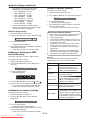
Preparation (continued)
Adjustment of the projection angle
For the best projection, project images on a flat screen
JOTUBMMFEBUEFHSFFTUPUIFnPPS*GOFDFTTBSZUJMUUIF
projector using the two adjustment feet on the bottom
of the projector.
Using the adjustment feet (front)
1. Tilt up the projector to the appropriate angle.
2. Rotate the adjustment feet (front) for fine
adjustment.
Important:
t *OTUBMMUIFTDSFFOPOBnBUXBMMBUEFHSFFTUPUIF
floor.
t 4MBOUJOHUIFQSPKFDUPSNPSFUIBO¡SJHIUBOE
MFGU
PS¡GSPOUBOESFBS
NBZDBVTFUSPVCMFPS
explosion of the lamp. You can tilt the projector up
to 8 degrees using the adjustment feet only.
t *NBHFTNBZOPUCFQSPKFDUFEJOBTIBQFPGB
regular rectangle or with its aspect ratio 4:3,
depending on the installation conditions of the
projector and the screen.
When projected images are
distorted to a trapezoid
When Auto Keystone in the Installation menu is set
to On, this projector automatically corrects vertical
keystone distortion. For fine adjustment, press the
KEYSTONE button on the projector or the remote
control to display Keystone, and adjust the image by
pressing the , button (or VOLUME , button
on the remote control).
In the following cases:
Press the button.
Press the button.
t *OUIFLFZTUPOFBEKVTUNFOUZPVDBOPCUBJOBO
optimum result when the LENS SHIFT dial is at the
factory default position. (See page 9.)
t 5IFBVUPNBUJDLFZTUPOFBEKVTUNFOUNBZOPU
be carried out correctly because of the ambient
temperature and the installation conditions of the
projector and the screen. In such cases, correct the
keystone manually.
t 8IFOUIFQSPKFDUPSJTQSPKFDUJOHJNBHFTXIFSF
acceleration is present, such as in a vehicle and
aircraft, the automatic keystone adjustment may
not function correctly. In such a case, set Auto
Keystone in the Installation menu to Off and correct
the keystone manually.
EN-16
Downloaded From projector-manual.com
t :PVDBODPSSFDUUIFWFSUJDBMLFZTUPOFT)PXFWFS
their adjustment ranges are limited in such
correction.
Important:
t 8IFOUIFLFZTUPOFBEKVTUNFOUJTDBSSJFEPVUUIF
adjustment value is indicated. Note that this value
doesn’t mean a projection angle.
t 5IFBMMPXBCMFSBOHFPGUIFBEKVTUNFOUWBMVFJO
the keystone adjustment varies depending on
the installation condition, input signal and aspect
settings in MENU.
t 8IFOUIFLFZTUPOFBEKVTUNFOUUBLFTFGGFDUUIF
resolution decreases. In addition, stripes may
appear or straight lines may bend in images with
complicated patterns. They are not due to product
malfunctions.
t /PJTFNBZBQQFBSPOUIFTDSFFOEVSJOHUIF
keystone adjustment because of the type of the
video signal being projected and the setting values
of the keystone adjustment. In such cases, set the
keystone adjustment values in the range where the
image is displayed without noise.
t 8IFOUIFLFZTUPOFBEKVTUNFOUJTDBSSJFEPVUUIF
image may not be displayed correctly because of
the type of input signal.
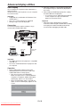
Basic operation
4
ON
STANDBY
MAGNIFY
ASPECT
1, 2
3
6
VOL
UP EFFICIENT
MODE
DOWN
KEYSTONE
3D
AUTO
POSITION
MENU
ENTER
AV
MUTE
VIEWER
FREEZE
VIDEO
1
COMPUTER
UNPLUG
USB DISP.
5
DVI
HDMI
t 5IFQSPKFDUPSTUBSUTXBSNJOHVQXIFOUIF108&3
button is pressed. During the warm-up process,
images may appear dark and no commands are
accepted.
t #ZCMJOLJOHSFEUIF45"564JOEJDBUPSJOEJDBUFTUIBU
the lamp should be replaced soon. Replace the
lamp when the STATUS indicator blinks red. (See
page 53 and 57.)
t *NBHFTNBZOPUCFQSPKFDUFEXJUIHPPERVBMJUZJO
an extremely hot or cold environment. (This is not a
product malfunction.)
t *OPSEFSUPFOTVSFUIFTBGFUZJODBTFPGUSPVCMFXJUI
the projector, use an electrical outlet having an
earth leakage breaker to supply the power to the
projector. If you do not have such outlet, ask your
dealer to install it.
4. Adjust the focus by turning the focus ring.
5. Choose your desired external input source using
the COMPUTER, HDMI, LAN DISP., USB DISP.,
VIEWER, VIDEO, or S-VIDEO button.
t 5IFJOQVUTPVSDFJTTXJUDIFECFUXFFO
Computer1, Computer2, HDMI, LAN Display,
USB Display, and PC Less Presentation at every
press of the COMPUTER button on the control
panel.
t 5IFJOQVUTPVSDFJTTXJUDIFECFUXFFO7JEFPBOE
S-Video at every press of the VIDEO button on
the control panel.
t 8IFOQSFTTJOHUIF$0.165&3PS
)%.*
LAN DISP., USB DISP., VIEWER, VIDEO, or
S-VIDEO button on the remote control, the input
source switches directly as the button pressed.
t :PVDBOOPUDIBOHFUIFJOQVUTPVSDFXIJMFUIF
menu is being displayed.
t 8IFO$PNQVUFSJTDIPTFOBTUIFTPVSDF
images supplied from the computer may flicker.
Press the or button on the remote control
to reduce flicker, if it occurs.
t 5PBWPJEQFSNBOFOUMZJNQSJOUJOHBmYFEJNBHF
onto your projector, please do not display the
same stationary images for long period.
1. Turn on the device connected to the projector first.
2. Plug the power cord in the wall outlet.
t 5IF108&3JOEJDBUPSMJHIUTVQ
t *GUIFQPXFSDPSEJTVOQMVHHFEGSPNUIFXBMM
outlet before the projector is cooled down
completely after use, the fans may start rotating
when the power cord is plugged in next time
and the POWER button may not function. In this
case, wait for the fans to stop and press the
POWER button to light the indicator.
3. Press the POWER button on the control panel or
the ON button on the remote control.
t *UNBZUBLFBCPVUPOFNJOVUFGPSUIFMBNQUP
light up.
t 5IFMBNQPDDBTJPOBMMZGBJMTUPMJHIUVQ8BJUB
few minutes and try to light the lamp again.
t "GUFSUIF108&3CVUUPOJTQSFTTFEUIFJNBHF
may flicker before the lamp becomes stable.
This is not a product malfunction.
t 3FHBSEMFTTPGUIFTFUUJOHPG-BNQ.PEFJOUIF
Installation menu, the Standard lamp mode is
activated by default whenever the projector
is turned on. The Lamp Mode is set to either
Standard or Low depending on the setting last
selected, and you cannot switch the Lamp
Mode in about one minute after the lamp is on.
STATUS
POWER
Green
Red
Green
Important:
t *GUIFMBNQFYDFQUJPOBMMZUVSOFEPGGEVFUPUIF
power interruption or voltage drop, it can happen
that the lamp does not turn on even if you switch
again the power supply on. In that case, please pull
the electric cord out of the consent and put it again
JOUIFDPOTFOUBCPVUNJOVUFTMBUFS
t %POPUDPWFSUIFMFOTXJUIUIFMFOTDBQXIJMFUIF
lamp is on.
EN-17
Downloaded From projector-manual.com
LAN DISP.
5
3, 1, 2
Power-on
Indicator
Condition
Stand-by
When the lamp is on.
S-VIDEO
2
Basic operation (continued)
6. Adjust the image size by turning the zoom ring.
7. Adjust the vertical position of the displayed image
by turning the LENS SHIFT dial.
t *GOFDFTTBSZBEKVTUUIFGPDVTBOE[PPNBHBJO
Direct Power OFF
When fine streaks are seen on projected
images
This is due to interference with the screen surface and
is not a malfunction. Replace the screen or displace
the focus a little.
Power-off
Use the following procedure to turn off the projector.
The lamp may deteriorate if the projector is powered
PGGBOEPOSFQFBUFEMZXJUIJONJOVUFTBGUFSUIFMBNQ
is lighted.
1. Press the POWER button on the control panel or
the STANDBY button on the remote control.
t 5IFNFTTBHFi1PXFS0GG 1SFTT again”
appears on the screen.
t 5PDBODFMQSFTTBOZCVUUPOFYDFQUUIF108&3
button.
(Some buttons on the remote control don’t
function for cancel.)
2. Press the POWER button on the control panel or
the STANDBY button on the remote control within
TFDPOETBHBJO
t 5IFMBNQXJMMHPPVUBOEUIF45"564JOEJDBUPS
will start blinking.
3. 8BJUBCPVUTFDPOETGPSUIF45"564JOEJDBUPSUP
be turned off.
4. Unplug the power cord.
t 5IF108&3JOEJDBUPSXJMMHPPVU
t *GUIFQPXFSDPSETIPVMECFVOQMVHHFE
accidentally while either the STATUS indicator is
blinking or the lamp is on, allow the projector to
DPPMEPXOGPSNJOVUFTXJUIUIFQPXFSPGG5P
light the lamp again, press the POWER button
(or ON button). If the lamp doesn’t light up
immediately, repeat pressing the POWER button
(or ON button) two or three times. If it should still
fail to light up, replace the lamp.
Important:
t 8IFOTUPSJOHUIFQSPKFDUPSJOUIFDBSSZJOHDBTFUIF
lens should face up.
Before carrying the projector, rotate the focus ring
and zoom ring to adjust the lens to the shortest.
This prevents the possible damages of the lens.
You can turn off this projector just by unplugging the
power cord without pressing the POWER button.
t %POUTIVUEPXOUIFQSPKFDUPSXIJMFUIF45"564
indicator is blinking after the lamp lights up
because the lamp’s life may be shortened.
t %POUUVSOUIFQSPKFDUPSCBDLPOSJHIUBGUFSTIVUUJOH
it down because the lamp’s life may be shortened.
8BJUBCPVUNJOVUFTCFGPSFUVSOJOHUIFQSPKFDUPS
back on.)
t #FGPSFTIVUUJOHEPXOUIFQSPKFDUPSCFTVSFUPDMPTF
the menu screen. If you shut down the projector
without closing the menu, the setting data of the
menu may not be saved.
t *GZPVTIVUEPXOUIFQSPKFDUPSXIJMFDPOUSPMMJOH
the projector using the network function, the
application software such as ProjectorView may
fail. For details, see “User Manual of LAN Control
Utility” contained in the CD-ROM.
AUTO POSITION button
When the image isn’t projected in the right position
with Computer selected as the input source, follow the
procedure below.
1. Project a bright image such as the “Recycle Bin”
window on the full screen.
2. If the screen saver is running, turn it off.
3. Press the AUTO POSITION button.
t *GUIFJNBHFJTTUJMMOPUJOUIFSJHIUQPTJUJPO
adjust the image position using the Signal menu.
See page 25.
Volume from the speaker
Press the VOLUME or button to change the
volume from the speaker.
The volume control bar will appear on the screen.
Volume
16
t 5IFWPMVNFDPOUSPMCBSXJMMEJTBQQFBSBCPVU
seconds after the VOLUME button is released.
t 5IF70-6.&CVUUPOTEPOUGVODUJPOXIJMFUIF
menu is being displayed.
t 8IFOBIJHIMFWFMBVEJPTJHOBMTVDIBTB%7%
audio signal, is supplied to the AUDIO IN terminal,
the output from the speaker may be distorted.
You can change the volume also by using the Volume
setting in the Audio menu.
(See page 22 for menu setting.)
1. Display the Audio menu.
2. Select Volume by pressing the or button.
3. Adjust the volume by pressing the or button.
4. Press the MENU button to exit the menu.
AV mute
The video and audio signals are temporarily muted
when the AV MUTE button is pressed. To cancel
muting, press the AV MUTE button again.
EN-18
Downloaded From projector-manual.com
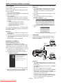
Basic operation (continued)
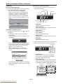
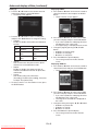
Setting the aspect ratio
Watching 3D content
You can change the aspect ratio of the input video
signal (or the ratio of width to height of the image).
Change the setting according to the type of the input
video signal.
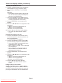
You can enjoy 3D content with this projector.
In order to watch 3D content, you need to have the
following items:
t 'JFMETFRVFOUJBM%WJEFPDPOUFOUT
t %-1-JOLBDUJWF%HMBTTFT
(Field-sequential: The system which displays
alternately the image for the left eye and the right eye.)
With the remote control:
1. Press the ASPECT button.
t &WFSZUJNFUIF"41&$5CVUUPOJTQSFTTFEUIF
aspect mode changes from Normal to 16:9, to
Full, and back to Normal.
L
With the Picture menu:
(See page 22 for menu setting.)
1. Display the Picture menu.
2. Select Aspect Ratio by pressing the or button.
Aspect Ratio
R
Checkerboard
L R
L
L
R
L
R
R
Supported
Not supported
Not supported
Normal
Sensor
L
L R
L R
L R
L R
L R
L R
L R
L R
L R
L R
L R
L R
L R
L R
L R
R
L R
L R
L R
R
R
3. Select your desired aspect ratio by pressing the
or button.
L
L R
L R
L
Not supported
The shutter timing of the 3D
glasses is controlled by
being synchronized with
switching of right and left
3D image which is detected
by the sensor of glasses.
R
L
When 16:9 is selected. (For XD700U only)
4. Press the ENTER button.
5. Select your desired position (Center, Upper or
Lower) by pressing the or button.
R
L
R
DLP™ Projector
L
DLP™ Link™ active
3D glasses
Play the field-sequential 3D video contents on a
computer or DVD player, and then, connect the cable
with the projector.
To cancel the menu:
6. Press the MENU button.
Go to the Picture menu (or press the 3D button on
the remote control) and set the 3D option to On.
(See page 23.)
Put on the 3D glasses to watch the contents.
If the contents are not projected correctly, go to the
Picture menu, and switch the 3D Sync Invert option to
On.
Important:
t 8IFOBJNBHFJTLFQUEJTQMBZFEGPSBMPOH
time before displaying 4:3 image, the afterimages
of the black bars may appear on the 4:3 image
screen. Consult your dealer in this case.
Caution:
t 5IFMBNQDBOUCFMJUBHBJOGPSPOFNJOVUFBGUFS
turned off for safety purpose. It will take another
one minute for the STATUS indicator to go out. If
you want to turn on the projector again, wait until
the indicator goes out, and then press the POWER
button.
t 5IFFYIBVTUGBOTSPUBUFGBTUFSBTUIFUFNQFSBUVSF
around the projector rises.
t 8IFOUIFUFNQFSBUVSFBSPVOEUIFQSPKFDUPSSJTFT
high, the sign “Temperature!!” blinks red on the
screen. If the temperature stays high, the lamp will
go out automatically.
Important:
t %POPUEJTQMBZBTUJMMQJDUVSFGPSBMPOHUJNF
because the afterimages may persist on the screen.
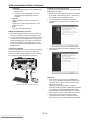
When connecting to a laptop computer:
When this projector is connected to a laptop
computer, there may be times when images may not
be projected. When it occurs, set the computer so that
it can output signals externally. The procedure varies
across computers in use. See the instruction manual
of your computer.
EN-19
Downloaded From projector-manual.com
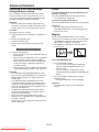
3D image Format
Side by side
Top & bottom
Page flipping
(Field sequential)
Important:
t :PVDBOOPUQSPKFDUUIF%DPOUFOUGSPNUIFJOQVU
source LAN Display, USB Display, and PC Less
Presentation.
t *GUIFWJFXJOHEJTUBODFJTOFBSFSUIBOUIF
recommended distance, it will cause physical
discomfort and eye fatigue.
t 8BUDIUIFDPOUFOUTJOGSPOUPGUIFTDSFFOOPUBUCJH
angle. If you are viewing the screen at big angle,
you may not be able to view 3D contents correctly.
t *GZPVBSFOPUWJFXJOH%DPOUFOUTDPSSFDUMZ
check to see if the 3D glasses are powered on or
adequately charged. See the instruction manual of
the 3D glasses for more information.
t 5IFSFBSFQFSTPOBMEJGGFSFODFTJOWJFXJOHUIF%
images. For persons with myopia, hypermetropia,
astigmatism or left and right sights, please wear
glasses to correct them then wear the 3D glasses.
t 5IFQJDUVSFTFFNTNJTQMBDFEBUUIFTUBSUPG
projecting the 3D images, however, this is not a
malfunction.
t 8JUIUIF%PQUJPOTFUUP0ODPOUFOUTEJTQMBZFE
on the projector appear darker. It is normal and
does not mean the projector is malfunctioning.
Basic operation (continued)
t 5IF."(/*':NPEFDBOOPUCFVTFEXIFOWJFXJOH
3D contents on the projector.
t *UNBZPDDVSUIBUUIFJNBHFNBZOPUCFFOPVHI%
image because setting such as fluorescent lighting
may occur loss of synchronism of glasses.
t %JNBHFNBZOPUBQQFBSPOUIFTDSFFOEFQFOEJOH
on the PC performance such as graphics board,
memory, or CPU.
t 5IFTJHOBMTTQFDJmFEJOUIFUBCMFPOQBHF
can be displayed with viewing 3D contents on
the projector. If a different signal is inputted, the
projector shows no 3D contents even with the 3D
option set to On in the Picture menu.
t *G%7%JTSVOCZQTJHOBMT%JNBHFNBZOPUCF
displayed correctly depending on the DVD player.
t 8IFO%JNBHFJTQSPKFDUFEPOUIFTDSFFOJO
)[PSVTJOHDFSUBJOUZQFPGQMBZCBDLTPGUXBSFPG
PC, the image may not appear on the screen.
Caution:
Notes on danger to public health during watching
3D image
t 4UPQWJFXJOHUIF%JNBHFJNNFEJBUFMZJGZPVGFFM
tired, discomfort, or any other abnormality. It may
cause you to feel unwell if continuing to watch the
3D image in such cases. Please take the necessary
rest, do not continue watch the 3D image for a long
time. Stop using the 3D glasses if you can clearly
see double images when viewing 3D content.
Prolonged use may cause eyesight fatigue.
t 5IFGPMMPXJOHQFPQMFOFFEUPSFGSBJOGSPNVTFBT
with 2D image.
t BQIPUPTFOTJUJWFQBUJFOU
t BQBUJFOUXJUIIFBSUEJTFBTF
t BQFSTPOJOQPPSQIZTJDBMDPOEJUJPO
t BTMFFQZQFSTPO
t BWFSZUJSFEQFSTPO
t BESVOLQFSTPO
t DIJMESFO
t 8IFOXBUDIJOH%NPWJFTUBLFBOBQQSPQSJBUF
break after watching a movie. When watching 3D
content on interactive devices such as 3D games
or computers, take an appropriate break every
NJOVUFT1SPMPOHFEVTFNBZDBVTFFZFTJHIU
fatigue.
t 8IFOZPVGFFMVODPNGPSUBCMFTUPQWJFXJOH
3D images and playing 3D games until you are
restored. If necessary, consult a doctor. Also,
stop driving a car until you are restored (for about
2 hours). The period to restore varies with the
individual.
t "TBHVJEF%HMBTTFTTIPVMEOPUCFVTFECZ
children younger than 5 - 6 years old. As it is
difficult to judge younger children’s reactions to
fatigue or discomfort, their physical condition may
deteriorate suddenly. When this product is being
used by a child, the parent or guardian should
check to ensure that the child’s eyes are not
becoming tired.
&/
Downloaded From projector-manual.com
t 8IFOWJFXJOHUIFQJDUVSFTUIBUSPMMPWFSBOE
shake or many dynamic pictures, if you feel
uncomfortable, please look at another place.
t 8IFOWJFXJOHDPOUFOUTXJUINPWFNFOUTTVDIBT
rotation, or horizontal or vertical oscillation, you
may feel as if you are actually moving. If such a
feeling results in discomfort, look away from the
screen.
t 8IFOVTJOHUIF%HMBTTFTCFDBSFGVMOPUUPTUSJLF
the screen or other people by mistake. As the
images are in 3D, you may mistake the distance
from the screen, causing to strike the screen which
may result in injury. When using the 3D glasses,
do not place breakable objects near the glasses.
You may move by mistaking the 3D objects you are
viewing as the real objects, causing damages to
surrounding objects that may lead to injury.
t 8IFOVTJOHUIF%HMBTTFTNBLFTVSFZPVSFZFT
are on an approximate horizontal level. If you
suffer from myopia (short sightedness), hyperopia
(far-sightedness), astigmatism, or have eyesight
differences between the left and right eyes, please
use corrective glasses or other such methods to
correct your eyesight before putting on the 3D
glasses.
t 8IFOZPVWJFXUIF%JNBHFTLFFQBEJTUBODF
from the screen of about three times the effective
height of the screen.
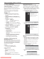
Menu operation
You can make various settings using the displayed menus.
Picture
Image
Brightness
Contrast
Color Temp.
Color Management
Aspect Ratio
Input Level
3D
3D Sync Invert
Video Image
Signal
Color
Sharpness
Tint
*1
*1
*1
H.Position
V.Position
Fine sync *1*2
Tracking
*2
Computer Input *2
Overscan
Hold
*2
User
Audio
Audio Input
Installation
Efficient Mode
Volume
Network Config
OK
*3
*5
*2
*1
*1
Projector Name
Network Certification
Network Password
IP Config
Wireless Setting
AMX Device Discovery
Network Initialization
Network Restart
Information
Lamp Time
Input
Resolution
H.Frequency
V.Frequency
Sync. Type
*4
*4
*4
Auto, RGB, YCbCr/YPbPr
*4
Begin
On
Off
End
Clamp Position *2
OK
Clamp Width *2
LPF
*1*2
Shutter(U)
Shutter(L)
Auto
Shutter(LS)
Audio 1 *6
Shutter(RS)
Audio 2 *6
Audio 3 *6
Mix
*6
Lamp Mode
Standby Mode
Auto Power Off
1-255
1-63
On, Off
Standard, Low
Low, LAN, Speaker Out, Monitor Out
OfG.JO.JO.JO.JO.JO
Upper Left, Upper Right, Center, Lower Left, Lower Right
Off, Mirror, Invert, Mirror Invert
Off, On
Off, On
Cross Hatch , White , Black
English,
, Español, Français, Italiano,
, Deutsch,
OK
Password
Cinema Mode
Video Signal
WXGA
Set Up
Image Capture
Splash Screen
Back Color
AV Mute Mode
Closed Caption
OK
Menu Position
Image Reverse
Auto Power On
Auto Keystone
Test Pattern
Language
Reset All
Option
Auto
Theater
Presentation
Standard
Black Board
White Board
Brilliant Color™
User
Dynamic, Natural, Detail
Gamma
Contrast R
Contrast G
Contrast B
Low
Mid
Brightness R
High
Brightness G
User
Brightness B
Red
Gain
Green
Saturation
Blue
Hue
Cyan
Yellow
Magenta
Normal
16:9
*7
Center, Upper, Lower *8
Full
Auto, Normal, Enhanced
Off, On
Off, On
Password
Change Password
, Türkçe, Magyar,
, Bahasa Malaysia
Off, On
xxxx
xxxxxxxx..., SET
On , Off
OK
OK
OK
Off , On
OK
OK
DHCP
IP Address
Subnet Mask
Default Gateway
MAC Address
DHCP Function
Start IP Address
End IP Address
IP Config Setup
SSID
Channel
Encryption
On, Off
xx-xx-xx-xx-xx-xx
Off, On
OK
xxxxxxxx..., SET
"VUP
SET , Off, WEP 128bit(ASCII), WEP 64bit(ASCII), WEP 128bit(HEX), WEP 64bit(HEX),
WPA-PSK(ASCII), WPA2-PSK(ASCII), WPA-PSK(HEX), WPA2-PSK(HEX)
OK
*1: Not available with certain signals.
*2: Not available when the input signal is from the VIDEO or S-VIDEO terminal.
"WBJMBCMFPOMZXIFOUIFJOQVUTJHOBMJT5757JPSJ
*4: The range that can be specified varies across input signals.
*5: Available only when the input signal is from the VIDEO or S-VIDEO terminal.
*6: Audio 1, Audio 2, Audio 3, and Mix cannot be selected when the input source is HDMI input.
*7: “ wJTOPUEJTQMBZFEBOEJTOPUBWBJMBCMFJO8%6
5IJTGVODUJPOJTOPUBWBJMBCMFJO8%6
EN-21
Downloaded From projector-manual.com
, Svenska, Indonesia,
Auto, Off
Auto, NTSC, PAL, SECAM, 4.43NTSC, PAL-M, PAL-N, P"-
OfG"VUPYY3#YYY
Auto, OfG
OK
Original, User, Off
Blue, Black, Image Original, Image User
Black, Image Original, Image User
Off, CC1, CC2, CC3, CC4, T1, T2
Wireless Setup
*2
, Polski, Português,
Menu operation (continued)
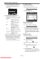
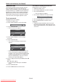
5. Set the selected item by pressing the or button.
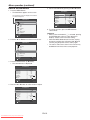
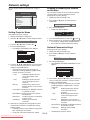
How to set the menus
1. Press the MENU button.
t 5IF.BJO.FOVBQQFBSTPOUIFTDSFFO
Installation
Efficient Mode
The item being selected is displayed in red letters
on a blue background.
Lower Right
Image Reverse
Off
Auto Power On
Off
Auto Keystone
Main Menu
Test Pattern
Language
Picture
OK
Menu Position
Reset All
Off
Cross Hatch
English
OK
Video Image
Adjust
RGB
Signal
MENU Exit
Select
Audio
Installation
6. To cancel the menu, press the MENU button
several times.
opt.
Option
Network Config
Information
Confirm
Important:
t When an item marked with “ ” is selected, pressing
the ENTER button makes its value effective or
displays another screen for further setting.
t 8IFOUIF.&/6CVUUPOEPFTOUGVODUJPOVOQMVH
UIFQPXFSDPSEGSPNUIFXBMMPVUMFU8BJUBCPVU
minutes, plug the power cord in, and try again.
t 5IFNFOVTBOETDSFFOTTIPXOJOUIJTNBOVBMNBZ
be different from those of the actual projector.
MENU Exit
Select
2. Press the or button to select a menu to use.
Main Menu
Picture
Video Image
RGB
Signal
Audio
Installation
opt.
Option
Network Config
Information
Confirm
MENU Exit
Select
3. Press the ENTER button (or button).
t 5IFTFMFDUFENFOVJTEJTQMBZFE
Installation
OK
Efficient Mode
Menu Position
Upper Left
Image Reverse
Off
Auto Power On
Off
Off
Auto Keystone
Cross Hatch
Test Pattern
English
Language
Reset All
OK
Adjust
MENU Exit
Select
4. Press the or button to select an item to adjust.
Installation
Efficient Mode
OK
Menu Position
Upper Left
Image Reverse
Off
Auto Power On
Off
Auto Keystone
Test Pattern
Language
Reset All
Adjust
Off
Cross Hatch
English
OK
MENU Exit
Select
EN-22
Downloaded From projector-manual.com
Menu operation (continued)
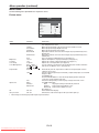
Menu items
Set the following items provided in the respective menus.
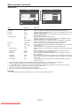
Picture menu
Picture
Auto
Image
0
Brightness
0
Contrast
Mid
Color Temp.
Color Management
Red
Aspect Ratio
Normal
Auto
Input Level
Off
3D
3D Sync Invert
Off
Adjust
MENU Exit
Select
ITEM
Image
SETTING
Auto
Theater
Presentation
Standard
Black Board
White Board
Brightness
Contrast
Color Temp.
Color Management
Aspect Ratio
User
4 options
Red / Green /
Blue / Cyan /
Yellow / Magenta
Normal
16:9
Full
Input Level
Auto /
Normal /
Enhanced
3D
3D Sync Invert
Off / On
Off / On
FUNCTION
Automatically sets an optimal color balance based on the input signal. Use
this setting for most cases.
Makes projected images soft and smooth. Best suited for movies.
Makes projected images bright and crisp.
Makes projected images look natural.
Reproduces natural color tones when images are projected directly onto a
black board.
Reproduces natural color tones when images are projected directly onto a
white board.
Use to set Gamma or BrilliantColor™. (See page 32.)
Adjusts the brightness of projected images. (See page 31.)
Adjusts the contrast of projected images. (See page 31.)
Adjusts the color temperature. (See page 31.)
You can change to any desired color by adjusting each of Gain, Saturation
and Hue of six different colors. (See page 32.)
Automatically sets the aspect ratio in relative to the input signal. Use this
setting for most cases.
Select to expand squeezed (or horizontally compressed) images such as DVD
images to 16:9.
'PS9%6POMZ
Press the ENTER button to select the image display position within the
screen from Center, Upper, and Lower.
Select this setting when you want to project images in the full screen.
For HDMI signal input:
Auto:
The proper setting is automatically selected.
Normal:
Select when grayish black occurs.
Enhanced: Select when solid black occurs.
(See page 13.)
Set to On/Off of 3D display.
Switches the order of the image for left eye and for right eye.
t 8IFO*NBHFJTTXJUDIFEQSPKFDUFEJNBHFTNBZCFEJTUPSUFE
EN-23
Downloaded From projector-manual.com
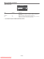
Menu operation (continued)
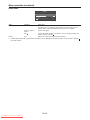
Video Image menu
Video Image
Color
0
Sharpness
0
0
Tint
Adjust
MENU Exit
Select
ITEM
Color
SETTING
Sharpness
Tint
FUNCTION
Adjusts the color tone of projected images. (See page 31.) You cannot select
this setting when the Computer1, Computer2, or HDMI is selected as the
input source.
Adjusts the sharpness of projected images. (See page 31.)
Adjusts the color tint of projected images. (See page 31.) You can select this
setting only when NTSC is selected as the input signal.
t :PVDBOOPUBEKVTU5JOUXIFOUIF571"-4&$".
TJHOBMJTJOQVUUFE
t 8IFO$PNQVUFS$PNQVUFSPS)%.*JTTFMFDUFE5JOUEPFTOPUXPSL
EN-24
Downloaded From projector-manual.com
Menu operation (continued)
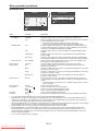
Signal menu
Signal
User
H. Position
0
Clamp Position
V. Position
0
Clamp Width
Fine sync
0
LPF
0
1
1
Off
Shutter(U)
0
Auto
Shutter(L)
0
Overscan
90%
Shutter(LS)
0
Hold
On
Shutter(RS)
0
User
OK
Tracking
Computer Input
Adjust
Adjust
MENU Exit
Select
MENU Exit
Select
ITEM
H. Position
V. Position
Fine sync
SETTING
Tracking
Computer Input
Auto
RGB
YCbCr/YPbPr
Overscan
Hold
Off / On
User
Clamp Position
OK
1-255
Clamp Width
LPF
Shutter(U)
1-63
On / Off
Shutter(L)
Shutter(LS)
Shutter(RS)
FUNCTION
Select this setting to adjust the horizontal position of projected images.
Select this setting to adjust the vertical position of projected images.
Select this setting to eliminate flickering or blurs, if they appear, when you are
viewing projected images.
Select this setting to eliminate vertical wide stripes, if they appear, when you are
viewing projected images.
Automatically sets the appropriate setting.
Select this setting when you connect the projector to high definition video
equipment having R, G, and B output terminals.
Select this setting when you connect the projector to a DVD player or other device
having Y, CB, and CR (or Y, PB, and PR) component video output terminals.
Use this setting to adjust the display area of projected images.
Use this setting to adjust projected images when flagging occurs in the upper
area of the screen.
The Signal-User menu is displayed for the following adjustments.
Use this setting to correct solid white or solid black that appears in projected
images.
Use this setting to correct solid black that appears in projected images.
Select this setting to enable or disable LPF.
Use this setting to adjust projected images when noise appears in the top
part of the image.
Use to adjust the image when noise appears on the bottom part of the image.
Use this setting to adjust projected images when noise appears in the left half
of the image.
Use this setting to adjust projected images when noise appears in the right
half of the image.
t )PSJ[POUBMTUSJQTNBZBQQFBSJOUIFFOMBSHFEQSPKFDUFEJNBHFUIPVHIUIFTFDPOEJUJPOTBSFOPUBNBMGVODUJPO
t 8IFOZPVDIBOHFUIFWBMVFPGUIFIPSJ[POUBMPSWFSUJDBMQPTJUJPOESBTUJDBMMZOPJTFNBZBQQFBS
t 5IFBEKVTUBCMFSBOHFPGUIFWFSUJDBMQPTJUJPOWBSJFTEFQFOEJOHPOUIFUZQFPGUIFJOQVUTJHOBM5IFJNBHFNBZCFTUBUJPOBSZ
even when the value is changed. These conditions are not a malfunction.
t 4IVUUFSEPFTOPUXPSLDPSSFDUMZEVSJOHLFZTUPOFBEKVTUNFOU
t 8IFOZPVJODSFBTFUIFWBMVFPG0WFSTDBOOPJTFNBZBQQFBSPOUIFTDSFFO
Important:
t :PVDBOTFUUIF1JDUVSF4JHOBMBOE4JHOBM6TFSNFOVTPOMZXIFOUIFTJHOBMJTJOQVUUFE
EN-25
Downloaded From projector-manual.com
Menu operation (continued)
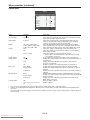
Audio menu
Audio
Audio Input
Auto
16
Volume
Adjust
MENU Exit
Select
ITEM
Audio Input
SETTING
Auto
Audio 1 / Audio 2 /
Audio 3
Mix
Volume
FUNCTION
Selects Audio 1 when the input source is Computer1, selects Audio 2 when
the input source is Computer2, selects Audio 3 when the input source is
Video/S-Video, and selects HDMI when the input source is HDMI.
Selects audio input.
Selects mix signal of Audio 1 and Audio 2. You can change the balance of
Audio 1/Audio 2 using Mix .
Adjusts the volume of the audio from the speaker.
t *O"VEJP*OQVU)%.*BVEJPJTTFMFDUFEXIFOUIFJOQVUTPVSDFJT)%.*JOQVU5IFBVEJPPG"VEJP"VEJP"VEJPBOE.JY
cannot be selected.
EN-26
Downloaded From projector-manual.com
Menu operation (continued)
Installation menu
Installation
Efficient Mode
Efficient Mode
OK
Lamp Mode
Standard
Menu Position
Upper Left
Standby Mode
Low
Image Reverse
Off
Auto Power Off
5Min
Auto Power On
Off
Auto Keystone
Test Pattern
Language
Reset All
Adjust
Adjust
Off
MENU Exit
Select
Cross Hatch
English
OK
MENU Exit
Select
ITEM
Efficient Mode
Lamp Mode
Standby Mode
SETTING
OK
Standard
Low
Low
LAN
Speaker Out
Monitor Out
Auto Power Off
Menu Position
Image Reverse
0GG.JO
5 options
Off
Mirror
Invert
Mirror Invert
Auto Power On
Off / On
Auto Keystone
Test Pattern
Off / On
Cross Hatch
White
Black
18 languages
OK
Language
Reset All
FUNCTION
Displays the Efficient Mode menu for the following settings.
Select this option when you want to view images in a well-lit room.
Select to moderate the intensity of the lamp. The operating sound is reduced
and the lamp lifetime becomes longer.
t 8IFOUIJTNPEFJTTXJUDIFEQSPKFDUFEJNBHFTNBZnJDLFS
t *GUIJTNPEFJTGSFRVFOUMZTXJUDIFEUIFMBNQNBZCFEFUFSJPSBUFE
Select this option when you don’t use the LAN control, speaker output and
monitor output during power standby. This option disables them and reduces
the power consumption during the power standby.
Select this option when you control the projector via the LAN during power
standby.
Select this option when you want to output audio from the speaker during
power standby.
Select this option when you want to output video signal from the MONITOR
OUT terminal in addition to the audio from the speaker during power standby.
Selects a desired timer setting until the projector enters the standby mode
when there is no signal input from the source.
Use this setting to change the position of the menu on the screen.
Select this setting when you want to view images from the front with the
projector set on the floor.
Select this setting when you want to view images from behind the screen with
the projector set on the floor.
Select this setting when you want to view images from behind the screen with
the projector set at the ceiling.
Select this setting when you want to view images from the front with the
projector set at the ceiling.
When this mode is set to On, the lamp is automatically lit when the power
cord is plugged in the wall outlet. Select On when you set the projector at the
ceiling.
t 8IFOUIFMBNQJTPGGUIFQSPKFDUPSJTJOTUBOECZ6TFUIFSFNPUFDPOUSPMUP
turn on the lamp.
Select Auto Keystone function.
Select to show the test cross hatch pattern.
Select to show the maximum brightness image.
Select to show the minimum brightness image.
Selects a desired language for the menu.
Resets all menu settings except for Password and Language to the default.
t :PVDBOEJTQMBZUIF&GmDJFOU.PEFNFOVBMTPCZQSFTTJOHUIF&''*$*&/5.0%&CVUUPO
t 3FHBSEMFTTPGUIFTFUUJOHPG-BNQ.PEFJOUIF*OTUBMMBUJPONFOVUIF4UBOEBSEMBNQNPEFJTBDUJWBUFECZEFGBVMUXIFOFWFS
the projector is turned on. The Lamp Mode is set to either Standard or Low depending on the setting last selected, and you
cannot switch the Lamp Mode in about one minute after the lamp is on.
t 8IFOUIF4UBOECZ.PEFJTTFUUP4QFBLFS0VUPS.POJUPS0VUUIFBVEJPTFMFDUFEXJUI"VEJP*OQVUJOUIF"VEJPNFOVJTPVUQVU
during standby mode. However, no audio is output when the last selected input was HDMI.
t %VSJOHTUBOECZNPEFZPVDBOOPUDIBOHFUIFBVEJPJOQVUBOEUIFWPMVNFGSPNUIFTQFBLFS
t 8IFO4UBOECZ.PEFJTTFUUP-"/4QFBLFS0VUPS.POJUPS0VUUIFGBOTSPUBUFBUWFSZMPXTQFFEEVSJOHTUBOECZBGUFS
plugging the power cord (with 5 second high speed rotation at the beginning) and after turning off the lamp. This is to cool
down the projector operating various functions during standby and is not a malfunction. When Standby Mode is set to Low,
the fans stop during standby.
t 5PDBODFMUIFUFTUQBUUFSOQSFTTBOZCVUUPO
EN-27
Downloaded From projector-manual.com
Menu operation (continued)
Option menu
Option
Password
OK
Cinema Mode
Auto
Video Signal
Auto
WXGA
Off
Set Up
Auto
Image Capture
OK
Original
Splash Screen
Back Color
Blue
AV Mute Mode
Black
Closed Caption
Off
Adjust
MENU Exit
Select
ITEM
Password
Cinema Mode
SETTING
OK
Auto / Off
Video Signal
8 options
WXGA
0GG"VUPY
Y3#Y
YY
Auto
Off
Set Up
Image Capture
Splash Screen
OK
Original
User
Back Color
Off
Blue / Black
Image Original
Image User
AV Mute Mode
Black
Image Original
Image User
Closed Caption
Off
CC1 / CC2 / CC3 / CC4 / T1 /
T2
FUNCTION
Use this setting to activate or deactivate the password lock.
Select Auto to automatically activate the film mode when the input
video signal is a video signal from a film.
Select Auto to automatically set the appropriate video format in
relative to the input signal. If projected images aren’t displayed
correctly, select a desired video format manually.
Select the appropriate format when the input signal is a WXGA
video signal and the Auto mode does not display images properly.
Select Off when the input signal is other than a WXGA video signal.
Select this setting to automatically change the Set Up mode.
Select this setting to lower the density of black. Use this setting
when images are dark.
Select this setting to increase the density of black.
t 8IFOJTTFUUIFCSJHIUOFTTJTEFDSFBTFECZUIFTFUVQ
cancel function for the U.S.
Use to capture the screen for the splash screen. (See page 47.)
Displays the original image for the splash screen when the projector
is powered on.
Displays the image captured for the splash screen when the
projector is powered on.
Displays no splash screen when the projector is powered on.
Displays blue or black background while no signal is inputted.
Displays the original image for the splash screen while no signal is
inputted.
Displays the image captured for the splash screen while no signal is
inputted.
Displays black background when the AV MUTE button is pressed.
Displays the original image for the splash screen when the AV MUTE
button is pressed.
Displays the image captured for the splash screen when the AV
MUTE button is pressed.
Does not display captions.
Displays captions.
t :PVDBOTFMFDU$JOFNB.PEFPOMZXIFOUIFJOQVUTJHOBMJTB5757JPSJWJEFPTJHOBM
t $BQUJPOTBSFOPUEJTQMBZFEXIJMFJOGPSNBUJPOBCPVUUIFNFOVWPMVNFTFUUJOHPSJOQVUTJHOBMTFMFDUJPOJTCFJOHEJTQMBZFEPO
the screen.
t 5IFDMPTFEDBQUJPOGVODUJPOEJTQMBZTUFYUJOGPSNBUJPOJODMVEFEJOUIF/54$TJHOBMXIJDIJTNBJOMZVTFEGPS57CSPBEDBTUJOHJO
North America.
EN-28
Downloaded From projector-manual.com
Menu operation (continued)
Network Config menu
IP Config
Network Config
Wireless Setting
On
Projector Name
SET
DHCP
Network Certification
On
IP Address
169 - 254 -
0
- 220
Network Password
OK
Subnet Mask
255 - 255 -
0
-
0
Encryption
IP Config
OK
Default Gateway
169 - 254 -
0
-
1
Wireless Setup
Wireless Setting
OK
MAC Address
AMX Device Discovery
Off
DHCP Function
Network Initialization
OK
Start IP Address
169 - 254 - 0
OK
End IP Address
169 - 254 - 254 - 254
OK
Network Restart
IP Config Setup
Adjust
SSID
SET
Channel
Auto
Off
OK
xx-xx-xx-xx-xx-xx
Adjust
Off
MENU Exit
Select
- 221
MENU Exit
Adjust
Select
MENU Exit
Select
ITEM
Projector Name
SETTING
xxxxxxxx...
SET
Network Certification
On
Network Password
IP Config
DHCP
OK
OK
On / Off
/ Off
IP Address
Subnet Mask
Default Gateway
MAC Address
DHCP Function
Start IP Address
xxx-xxx-xxx-xxx
xxx-xxx-xxx-xxx
xxx-xxx-xxx-xxx
xx-xx-xx-xx-xx-xx
On / Off
xxx-xxx-xxx-xxx
End IP Address
xxx-xxx-xxx-xxx
IP Config Setup
Wireless Setting
SSID
Channel
Encryption
Wireless Setup
AMX Device Discovery
Network Initialization
Network Restart
OK
OK
xxxxxxxx...
SET
Auto / 1 / 2 / 3 / 4 / 5 /
SET / Off /
WEP 128bit(ASCII) /
WEP 64bit(ASCII) /
WEP 128bit(HEX) /
WEP 64bit(HEX) /
WPA-PSK(ASCII) /
WPA2-PSK(ASCII) /
WPA-PSK(HEX) /
WPA2-PSK(HEX)
OK
Off / On
OK
OK
FUNCTION
Displays Projector Name. Displays Projector Name in blank when
Projector Name is not set.
Set Projector Name. Enter up to 15 character alphabets (capital/small),
numeric characters, or marks.
Select whether to enable the network certification or not. Select On for
normal use.
Set the password for PJLink certification.
Select this setting for IP Configuration. (See page 35.)
Use this setting when you obtain IP Config automatically by DHCP
server.
Displays IP Address.
Displays Subnet Mask.
Displays Default Gateway.
Displays MAC Address.
Use this setting when the projector behaves as a DHCP server.
Displays Start IP Address. However, Start IP Address is not set as
factory default, and cannot be displayed.
Displays End IP Address. However, End IP Address is not set as
factory default, and cannot be displayed.
Set the IP configuration.
Select this setting for wireless configuration.
Displays SSID.
Set SSID. Enter up to 32 characters (alphabets or numeric characters).
Select the wireless channel.
Select the wireless encrypted communication.
Set the wireless configuration.
Use this setting when using an AMX controller.
Initializes network setting.
Restarts network function.
EN-29
Downloaded From projector-manual.com
Menu operation (continued)
Information menu
Information
2000H
Lamp Time
Computer1
Input
Resolution
1024x768
H. Frequency
60.00 kHz
V. Frequency
60.00 Hz
3Wire
Sync. Type
MENU Exit
ITEM
Lamp Time
DESCRIPTION
Resolution
This menu shows a lamp operating time (hour) calculated assuming that Lamp Mode is Low.
t 8IFOUIF-BNQ.PEFJT4UBOEBSEUIJTNFOVTIPXTBMPOHFSMBNQPQFSBUJOHUJNFUIBOUIF
actual time. (See page 52 for the interval of lamp replacement.)
Indicates the name of the terminal to which the currently projected video signal is being
inputted.
Indicates the resolution of the currently projected video signal.
H. Frequency
Indicates the horizontal frequency of the currently projected video signal.
V. Frequency
Sync. Type
Indicates the vertical frequency of the currently projected video signal.
Indicates the type of the sync signal for the currently projected video signal.
Input
&/
Downloaded From projector-manual.com
Image adjustment
To adjust the brightness (Contrast
and Brightness):
To adjust the tone of white (Color
Temp.):
You can make adjustments for the brightness of the
projected image using the menu.
(See page 22 for menu setting.)
1. Display the Picture menu.
2. Select Contrast or Brightness by pressing the or
button.
3. Adjust the selected item by pressing the or button.
To cancel the menu:
4. Press the MENU button.
You can select a preset color temperature (white tone)
using the menu.
(See page 22 for menu setting.)
1. Display the Picture menu.
2. Select Color Temp. by pressing the or button.
3. Select your desired color temperature by pressing
the or button.
To cancel the menu:
4. Press the MENU button.
Contrast
To adjust the tone of white (To customize
the color temperature):
Select to adjust the contrast of the image. Every time
the button is pressed, the image becomes brighter
and more clearly defined. Every time the button is
pressed, the image becomes darker and less clearly
defined.
To set (and store) a user-defined color temperature,
perform the following procedure.
(See page 22 for menu setting.)
1. Select Color Temp. in the Picture menu.
2. Press the or button to select User .
3. Press the ENTER button.
t 5IF$PMPS5FNQ6TFSNFOVBQQFBST
Brightness
Every time the button is pressed, the image
becomes brighter. Every time the button is pressed,
the image becomes darker.
Color Temp. User
To adjust the color (Color and Tint):
Contrast R
0
Contrast G
0
Contrast B
0
Brightness R
0
Brightness G
0
You can adjust the color of the projected image using
the menu.
(See page 22 for menu setting.)
1. Display the Video Image menu.
2. Select Color or Tint by pressing the or button.
t $PMPSBOE5JOUJTTFMFDUBCMFPOMZXIFOUIFJOQVU
signal is Video.
t 5JOUJTTFMFDUBCMFPOMZXIFOUIF/54$PS
4.43NTSC signal is inputted.
3. Adjust the selected item by pressing the or
button.
To cancel the menu:
4. Press the MENU button.
4. Press the or button to select the desired item.
5. Press the or button to adjust the selected
item.
6. Repeat steps 4 and 5 for optimum adjustment
results.
To cancel the menu:
7. Press the MENU button.
Color
To enable the stored color temperature:
Use to adjust the color density of the projected image.
Every time the button is pressed, the color becomes
darker. Every time the button is pressed, the color
becomes lighter.
1. Set Color Temp. to User
Adjust
in the Picture menu.
About color temperature
There are different variations in white color. Color
temperature is a way to show these variations in
white. When the temperature is low, white appears
reddish. When the temperature rises, white
appears bluish. For example, you can change the
temperature using the following procedures.
To raise the temperature: Increase Contrast B (blue)
and decrease Contrast R (red).
To reduce the temperature: Decrease Contrast B
(blue) and increase Contrast R (red).
t *GZPVTFU$POUSBTU3(BOE#UPOFHBUJWF
values, the brightness of the image can’t retain
the original even when you maximize the value of
Contrast in the Picture menu.
Use to adjust the tint of the projected image. Every
time the button is pressed, the image appears more
greenish. Every time the button is pressed, the
image appears more reddish.
To sharpen or soften the projected
image (Sharpness):
Downloaded From projector-manual.com
MENU Exit
Select
Tint
You can adjust the sharpness of the projected image
using the menu.
(See page 22 for menu setting.)
1. Display the Video Image menu.
2. Select Sharpness by pressing the or button.
3. Adjust the selected item by pressing the or button.
To cancel the menu:
4. Press the MENU button.
0
Brightness B
EN-31
Image adjustment (continued)
Image
Color Management
You can set user-defined values for the brightness and
hue using the menu. (See page 22 for menu setting.)
1. Display the Picture menu.
2. Select Image by pressing the or button.
3. Select User by pressing the or button.
4. Press the ENTER button.
t 5IF*NBHF6TFSNFOVBQQFBST
You can individually adjust the tone of red, green, blue,
cyan, yellow and magenta using the menu.
1. Display the Picture menu.
2. Press the or button to select Color
Management.
3. Press the or button to select a color to be
adjusted: Red, Green, Blue, Cyan, Yellow or
Magenta.
4. Press the ENTER button.
t 5IFColor Management menu for the selected
color appears on the screen.
Image User
10
Brilliant Color™
Gamma
Adjust
Dynamic
MENU Exit
Color Management-Red
Select
5. Select a setting you want to set.
Gamma
0
Saturation
0
Hue
0
Adjust
Use this setting to set an optimal gamma value and
modulation of lamp power. The level of brightness can
be adjusted for subdued colors.
MENU Exit
Select
5. Press the or button to select an item to be
adjusted: Gain, Saturation or Hue.
6. Press the or button to adjust the item.
To cancel the menu:
7. Press the MENU button.
Dynamic
…… Select when viewing crisp, clear
images in a brightly lit room or strong
daylight. The level of brightness is
adjusted to higher levels.
Natural ……… Select when viewing images of which
colors are more faithfully reproduced.
The level of brightness and vividness
is adjusted to optimal levels.
Detail ………… Select when viewing images of which
brightness should be kept relatively
low, such as movies and music video
clips.
BrilliantColor™
Use this setting to make colors with medium
brightness, such as yellow and the skin tone appear
natural. Press the button to decrease the value to
lessen the effect. Press the button to increase the
value to heighten the effect. (BrilliantColor™ has no
FGGFDUBUWBMVF
6. Select a value by pressing the or button.
t 'PSNPSFFOIBODFEDPMPSSFQSPEVDUJPOTFU
BrilliantColor™UP5IFXIJUFBSFBPGUIFDPMPS
wheel is disabled, and you can reproduce truecolor images.
EN-32
Downloaded From projector-manual.com
Gain
Image adjustment (continued)
How to adjust the computer image
Simple method to adjust the image
position
This projector automatically and properly projects
video signals being inputted from the computer.
However, some video signals may not be projected,
depending on the type of the computer. When it
occurs, press the AUTO POSITION button. (See page
18.) When the signal is still not projected properly,
adjust the projected image using the Signal menu.
To adjust the horizontal position:
1. Align the left edge of the image with the left side
of the screen by adjusting H.Position. Then, align
the right edge of the image with the right side of
the screen by adjusting Tracking.
2. Repeat step 1 to complete the adjustment of the
horizontal position.
How to adjust the image supplied from the
computer using the menu:
To adjust the vertical position:
3. Align the upper edge of the image with the upper
side of the screen by adjusting V.Position.
Perform the following procedures when the following
conditions occur.
When wide strips appear.
…… Adjust Tracking in the Signal menu.
When the projected image flickers.
When the projected image is blurred.
…… Adjust Fine sync in the Signal menu.
When the projected image is displaced horizontally.
…… Adjust H.Position in the Signal menu. Every time
the button is pressed, the image moves to the
right. Every time the button is pressed, the
image moves to the left.
When the projected image is displaced vertically.
…… Adjust V.Position in the Signal menu. Every
time the button is pressed, the image moves
down. Every time the button is pressed, the
image moves up.
When the top part of the image flags.
…… Change the setting of Hold in the Signal menu.
To select On , press the ENTER button, and
Adjust Begin or End to minimize the flagging.
A solid black or solid white appears in the image.
…… Adjust Clamp Position or Clamp Width in the
Signal-User menu.
Noise appears in the right or left half of the image.
…… Adjust Shutter(LS) or Shutter(RS) in the SignalUser menu.
Noise appears in the top or bottom part of the image.
…… Adjust Shutter(U) or Shutter(L) in the Signal-User
menu.
1. Display the Signal menu.
2. Press the or button to select a setting to
adjust.
3. Adjust the selected setting by pressing the or
button.
LPF (Progressive filter)
You can select to enable or disable the LPF. This
option is set to Off normally.
Vertical or horizontal streaks may appear in the
projected image, depending on the type of the DVD
player, game console or computer in use. If this
occurs, reduce noise by enabling the LPF. Projected
images appear slightly faint.
To cancel the menu:
4. Press the MENU button.
t %POPUDIBOHFUIFTFUUJOHTPGUIF4JHOBMNFOV
for ordinary use.
EN-33
Downloaded From projector-manual.com
Network settings
You can set the network of the projector using the
menu.
Enabling or disabling the network
certification
You can select whether or not to certify the network
communication using the network password.
(See page 22 for menu setting.)
1. Display the Network Config menu.
2. Press the or button to select Network
Certification.
Network Config
Projector Name
SET
Network Certification
On
Network Password
OK
IP Config
OK
Wireless Setting
OK
AMX Device Discovery
Off
Network Initialization
OK
OK
Network Restart
Adjust
On
Network Certification
MENU Exit
Select
3. Press the ENTER button.
t $FSUJmDBUJPOEJBMPHBQQFBST
Setting Projector Name
CERTIFICATION :
(See page 22 for menu setting.)
1. Display the Network Config menu.
2. Press the or button to select Projector Name.
3. Press the or button to select SET .
4. Press the ENTER button.
t 5IF130+&$503/".&TDSFFOBQQFBST
Network Password settings
(See page 22 for menu setting.)
1. Display the Network Config menu.
2. Press the or button to select Network
Password.
PROJECTOR NAME
123456789012345
A
B
C
D
E
F
G
H
I
J
K
L
M
DEL
N
O
P
Q
R
S
T
U
V
W X
Y
Z
caps
0
1
2
3
4
5
6
7
8
9
–
.
_
!
”
#
$
%
’
(
)
*
+
,
/
CANCEL : MENU
4. Press the or button to select ON or OFF .
5. Select the item to set, and press the ENTER button.
t 5PDBODFMUIFTFUUJOHQSFTTUIF.&/6CVUUPO
t *UNBZUBLFTPNFUJNFUPSFnFDUUIFTFUUJOH
SET
Projector Name
ON
OK : ENTER
NEXT
OK
Network Password
SPACE
CLEAR
OK
CANCEL
5. Press the , ,, and buttons to move the key
cursor to select the characters or marks to enter,
and press the ENTER button.
t 1SPKFDUPS/BNFDBOCFTFUVTJOHVQUP
characters including alphabets (capital/small),
numeric characters, or marks.
key:
Shifting the position of enter
cursor to the left for each
character.
key:
Shifting the position of enter
cursor to the right for each
character.
DEL key:
Deleting the character in the
position of enter cursor for each
character.
caps/CAPS key: Switching an alphabet character
to CAPITAL or small.
NEXT/PREV key: Switching the marks listed on
the fourth line.
SPACE key:
Inserting a space in the position
of enter cursor.
CLEAR key:
Deleting all the entered
characters.
6. Select OK to complete the setting with the name
stored. Select CANCEL to complete the setting
without storing.
t 5IFEJTQMBZSFUVSOTUPUIF/FUXPSL$POmHNFOV
after selecting OK or CANCEL.
t *UNBZUBLFTPNFUJNFUPSFnFDUUIFTFUUJOH
EN-34
Downloaded From projector-manual.com
3. Press the ENTER button.
t 5IF$633&/5/&5803,1"44803%TDSFFO
appears.
CURRENT NETWORK PASSWORD
A
B
C
D
E
F
G
H
I
J
K
L
M
DEL
N
O
P
Q
R
S
T
U
V
W X
Y
Z
caps
0
1
2
3
4
5
6
7
8
9
OK
CLEAR
CANCEL
4. Press the , ,, and buttons to move the key
cursor to select the characters or marks to enter,
and press the ENTER button.
t 1BTTXPSEDBOCFTFUVTJOHVQUPDIBSBDUFST
including alphabets (capital/small) or numeric
characters.
key:
Shifting the position of enter
cursor to the left for each
character.
key:
Shifting the position of enter
cursor to the right for each
character.
DEL key:
Deleting the character in the
position of enter cursor for each
character.
caps/CAPS key: Switching an alphabet character
to CAPITAL or small.
CLEAR key:
Deleting all the entered
characters.
t 5IFEFGBVMUQBTTXPSEJTiBENJOw
Network settings (continued)
5. Select OK, and NEW NETWORK PASSWORD
screen appears if the entered password is correct.
t *GUIFFOUFSFEQBTTXPSEJTOPUDPSSFDUUIF
CURRENT NETWORK PASSWORD screen
appears again.
IP Config settings
(See page 22 for menu setting.)
1. Display the Network Config menu.
2. Press the or button to select IP Config.
NEW NETWORK PASSWORD
OK
IP Config
CONFIRM NETWORK PASSWORD
A
B
C
D
E
F
G
H
I
J
K
L
M
DEL
N
O
P
Q
R
S
T
U
V
W X
Y
Z
caps
0
1
2
3
4
5
6
7
8
9
OK
3. Press the ENTER button.
t 5IF*1$POmHNFOVBQQFBST
IP Config
CLEAR
CANCEL
On
DHCP
6. Enter the NEW NETWORK PASSWORD and
CONFIRM NETWORK PASSWORD.
t 1BTTXPSEDBOCFTFUVTJOHVQUPDIBSBDUFST
including alphabets (capital/small) or numeric
characters.
key:
Shifting the position of enter
cursor to the left for each
character.
key:
Shifting the position of enter
cursor to the right for each
character.
key:
Shifting the position of
enter cursor between NEW
NETWORK PASSWORD
and CONFIRM NETWORK
PASSWORD.
DEL key:
Deleting the character in the
position of enter cursor for each
character.
caps/CAPS key: Switching an alphabet character
to CAPITAL or small.
CLEAR key:
Deleting all the entered
characters.
7. When NEW NETWORK PASSWORD and CONFIRM
NETWORK PASSWORD are matched, the setting is
completed after changing the Network Password.
t *GUIFFOUFSFEDPOUFOUJTOPUNBUDIFE/&8
NETWORK PASSWORD screen appears again
after an error dialog is displayed.
t *UNBZUBLFTPNFUJNFUPSFnFDUUIFTFUUJOHT
IP Address
169 - 254 -
0
- 220
Subnet Mask
255 - 255 -
0
-
0
Default Gateway
169 - 254 -
0
-
1
MAC Address
xx-xx-xx-xx-xx-xx
Off
DHCP Function
Start IP Address
169 - 254 - 0
End IP Address
169 - 254 - 254 - 254
OK
IP Config Setup
Adjust
- 221
MENU Exit
Select
Setting or clearing DHCP
1. Display the IP Config menu.
2. Press the or button to select DHCP.
On
DHCP
3. Press the or button to select On or Off.
t 5PDBODFMUIFTFUUJOHQSFTTUIF.&/6CVUUPO
t 8IFO%)$1JTTFUUP0O*1"EESFTT4VCOFU
Mask, Default Gateway, and DHCP Function
cannot be set. If you want to set these settings,
set DHCP to Off and perform the IP settings as
follows.
IP Address settings
1. Display the IP Config menu.
2. Press the or button to select IP Address.
IP Address
169 - 254 -
0
- 220
0
- 220
3. Press the ENTER button.
t 5IFmSTUPDUFUJTTFMFDUFE
IP Address
169 - 254 -
4. Press the or button to select the numeric
value.
5. Press the or button to select the octet.
t 5IFTFDPOEPSmOBMPDUFUJTTFMFDUFE
IP Address
169 - 254 -
0
- 220
6. Press the ENTER button.
t 5PDBODFMUIFTFUUJOHQSFTTUIF.&/6CVUUPO
t 4FUUIFOVNFSJDWBMVFXJUIJOUIFSBOHFGSPNUP
255. However, set the numeric value for the final
octet within the range from 1 to 254.
EN-35
Downloaded From projector-manual.com
Network settings (continued)
Subnet Mask settings
Start IP Address setting
1. Display the IP Config menu.
2. Press the or button to select Subnet Mask.
1. Display the IP Config menu.
2. Press the or button to select Start IP Address.
Subnet Mask
255 - 255 -
0
-
0
Start IP Address
3. Press the ENTER button.
t 5IFmSTUPDUFUJTTFMFDUFE
Subnet Mask
255 - 255 -
0
-
0
Start IP Address
255 - 255 -
0
-
0
Start IP Address
Default Gateway settings
0
-
0
-
169 - 254 -
0
-
169 - 254 -
0
- 224
0
- 224
3. Press the ENTER button.
t 5IFmSTUPDUFUJTTFMFDUFE
1
End IP Address
4. Press the or button to select the numeric
value.
5. Press the or button to select the octet.
t 5IFTFDPOEPSmOBMPDUFUJTTFMFDUFE
Default Gateway
- 221
6. Press the ENTER button.
t 4FUUIFOVNFSJDWBMVFXJUIJOUIFSBOHFGSPNUP
255. However, set the numeric value for the final
octet within the range from 2 to 254. Moreover,
set the numeric value larger than IP address in
the same subnet class.
End IP Address
169 - 254 -
169 - 254 - 0
1. Display the IP Config menu.
2. Press the or button to select End IP Address.
1
3. Press the ENTER button.
t 5IFmSTUPDUFUJTTFMFDUFE
Default Gateway
- 221
End IP Address setting
1. Display the IP Config menu.
2. Press the or button to select Default Gateway.
169 - 254 -
169 - 254 - 0
4. Press the or button to select the numeric
value.
5. Press the or button to select the octet.
t 5IFTFDPOEPSmOBMPDUFUJTTFMFDUFE
6. Press the ENTER button.
t 5PDBODFMUIFTFUUJOHQSFTTUIF.&/6CVUUPO
t 4FUUIFOVNFSJDWBMVFXJUIJOUIFSBOHFGSPNUP
255. However, set the numeric value for the final
PDUFUXJUIJOUIFSBOHFGSPNUP
Default Gateway
- 221
3. Press the ENTER button.
t 5IFmSTUPDUFUJTTFMFDUFE
4. Press the or button to select the numeric
value.
5. Press the or button to select the octet.
t 5IFTFDPOEPSmOBMPDUFUJTTFMFDUFE
Subnet Mask
169 - 254 - 0
169 - 254 -
4. Press the or button to select the numeric
value.
5. Press the or button to select the octet.
t 5IFTFDPOEPSmOBMPDUFUJTTFMFDUFE
1
End IP Address
6. Press the ENTER button.
t 5PDBODFMUIFTFUUJOHQSFTTUIF.&/6CVUUPO
t 4FUUIFOVNFSJDWBMVFXJUIJOUIFSBOHFGSPNUP
255. However, set the numeric value for the final
octet within the range from 1 to 254.
169 - 254 -
0
- 224
Setting or clearing DHCP Function
6. Press the ENTER button.
t 4FUUIFOVNFSJDWBMVFXJUIJOUIFSBOHFGSPNUP
255. However, set the numeric value for the final
octet within the range from 3 to 254. Moreover,
set the numeric value larger than Start IP
address in the same subnet class.
1. Display the IP Config menu.
2. Press the or button to select DHCP Function.
IP Config Setup setting
DHCP Function
On
1. Display the IP Config menu.
2. Press the or button to select IP Config Setup.
3. Press the or button select On or Off.
t 5PDBODFMUIFTFUUJOHQSFTTUIF.&/6CVUUPO
t 8IFO%)$1'VODUJPOJTTFUUP0GG4UBSU*1
Address and End IP Address cannot be set.
If you want to set these settings, set DHCP
Function to On and perform the IP settings as
follows.
IP Config Setup
3. Press the ENTER button.
t $POmSNBUJPOEJBMPHBQQFBST
4. If the ENTER button is pressed again, the IP Config
setting will be reflected.
t *UNBZUBLFTPNFUJNFUPSFnFDUUIFTFUUJOH
EN-36
Downloaded From projector-manual.com
OK
Network settings (continued)
Wireless Setting
Channel setting
(See page 22 for menu setting.)
1. Display the Network Config menu.
2. Press the or button to select Wireless Setting.
1. Display the Wireless Setting menu.
2. Press the or button to select Channel.
OK
Wireless Setting
3. Press the or button to select Auto or 1 to 11.
t 5PDBODFMUIFTFUUJOHQSFTTUIF.&/6CVUUPO
3. Press the ENTER button.
t 5IF8JSFMFTT4FUUJOHNFOVBQQFBST
Encryption setting
1. Display the Wireless Setting menu.
2. Press the or button to select Encryption.
Wireless Setting
SSID
SET
Channel
Auto
Off
Encryption
Off
Encryption
Auto
Channel
OK
Wireless Setup
Adjust
3. Press the or button to select SET .
4. Press the ENTER button.
t &ODSZQUJPOEJBMPHBQQFBST
MENU Exit
Select
SSID setting
OK : ENTER
3. Press the or button to select SET .
4. Press the ENTER button.
t 5IF44*%TDSFFOBQQFBST
KEY
SSID
123456789012345
123456789012345
A
B
CANCEL : MENU
5. Press the or button to select OFF or another
encryption.
6. Select the item to set, and press the ENTER button.
t 5IF,&:TDSFFOBQQFBST
t 5PDBODFMUIFTFUUJOHQSFTTUIF.&/6CVUUPO
SET
SSID
OFF
ENCRYPTION :
1. Display the Wireless Setting menu.
2. Press the or button to select SSID.
C
D
E
F
G
H
I
J
K
N
O
P
Q
R
S
T
U
V
W X
0
1
2
3
4
5
6
7
8
9
L
Y
M
Z
A
B
C
D
E
F
G
H
I
J
K
L
M
DEL
caps
N
O
P
Q
R
S
T
U
V
W X
Y
Z
caps
SPACE
0
1
2
3
4
5
6
7
8
9
SPACE
CLEAR
CLEAR
OK
OK
CANCEL
5. Press the , ,, and buttons to move the key
cursor to select the characters or marks to enter,
and press the ENTER button.
t 44*%DBOCFTFUVTJOHVQUPDIBSBDUFST
including alphabets (capital/small) or numeric
characters.
key:
Shifting the position of enter
cursor to the left for each
character.
key:
Shifting the position of enter
cursor to the right for each
character.
DEL key:
Deleting the character in the
position of enter cursor for each
character.
caps/CAPS key: Switching an alphabet character
to CAPITAL or small.
CLEAR key:
Deleting all the entered
characters.
6. Select OK to complete the setting with the SSID
stored. Select CANCEL to complete the setting
without storing.
t 5IFEJTQMBZSFUVSOTUPUIF8JSFMFTT4FUUJOHNFOV
after selecting CANCEL.
EN-37
Downloaded From projector-manual.com
DEL
CANCEL
7. Press the , ,, and buttons to move the key
cursor to select the characters or marks to enter,
and press the ENTER button.
t ,&:DBOCFTFUVTJOHVQUPDIBSBDUFST
including alphabets (capital/small) or numeric
characters.
key:
Shifting the position of enter
cursor to the left for each
character.
key:
Shifting the position of enter
cursor to the right for each
character.
DEL key:
Deleting the character in the
position of enter cursor for each
character.
caps/CAPS key: Switching an alphabet character
to CAPITAL or small.
CLEAR key:
Deleting all the entered
characters.
8. Select OK to complete the setting with the
Encryption and KEY stored. Select CANCEL to
complete the setting without storing.
t 5IFEJTQMBZSFUVSOTUPUIF8JSFMFTT4FUUJOHNFOV
after selecting CANCEL.
Network settings (continued)
t 5IFOVNCFSPGDIBSBDUFSTPG,&:WBSJFT
depending on the Encryption setting.
t 8&1CJU"4$**
DIBST
t 8&1CJU"4$**
DIBST
t 8&1CJU)&9
EJHJUT
t 8&1CJU)&9
EJHJUT
t 81"14,"4$**
DIBST
t 81"14,"4$**
DIBST
t 81"14,)&9
EJHJUT
t 81"14,)&9
EJHJUT
t *GUIFFOUFSFEDPOUFOUJTPVUTJEFDIBSBDUFS
number range, the KEY screen appears again
after an error dialog is displayed.
Restart of network function
(See page 22 for menu setting.)
1. Display the Network Config menu.
2. Press the or button to select Network Restart.
Network Restart
3. Press the ENTER button.
t /FUXPSL3FTUBSUEJBMPHBQQFBST
4. If the ENTER button is pressed again, the network
function will be restarted.
t *UNBZUBLFTPNFUJNFUPSFTUBSUUIFGVODUJPO
Wireless Setup setting
How to use network function
1. Display the Wireless Setting menu.
2. Press the or button to select Wireless Setup.
t 8IFODPOOFDUJOHBDPNQVUFSBOEQSPKFDUPSXJUI
LAN, configure the both IP Addresses in the
same network group.
If connecting in different network group, be sure
to use a router. As for the settings of a router, ask
the network administrator.
t $POmHVSFUIF*1$POmHDPSSFDUMZ*GUIFTFUUJOHT
are not correct, the communication may be
unavailable. For the detail, consult the network
administrator.
t %FQFOEJOHPOUIFTFUUJOHTPG4UBOECZ.PEFPG
the projector, LAN function may be unavailable.
See page 27 for the detail of Standby Mode.
OK
Wireless Setup
3. Press the ENTER button.
t $POmSNBUJPOEJBMPHBQQFBST
4. If the ENTER button is pressed again, the Wireless
Setting will be reflected.
t *UNBZUBLFTPNFUJNFUPSFnFDUUIFTFUUJOH
Enabling or disabling the AMX
Device Discovery
Select this setting when using the AMX controller.
(See page 22 for menu setting.)
1. Display the Network Config menu.
2. Press the or button to select AMX Device
Discovery.
Glossary
For more detail of the glossary below, refer to the
technical book that is commercially available.
Off
AMX Device Discovery
3. Press the ENTER button.
t ".9EJBMPHBQQFBST
AMX :
OK : ENTER
Term
Description
DHCP
Abbreviation for Dynamic Host
Configuration Protocol. This
protocol automatically assigns IP
Address to networked devices.
IP Address
Numerical address to identify
networked computers.
Subnet Mask
A numeric value to define the
number of bits used for a network
address of a divided network (or
subnet) in an IP Address.
OFF
CANCEL : MENU
4. Press the or button to select ON or OFF .
5. Select the item to set, and press the ENTER button.
t 5PDBODFMUIFTFUUJOHQSFTTUIF.&/6CVUUPO
t *UNBZUBLFTPNFUJNFUPSFnFDUUIFTFUUJOH
A server (or router) to communicate
Default Gateway across networks (subnets) that are
divided by Subnet Mask.
Initialization of network settings
(See page 22 for menu setting.)
1. Display the Network Config menu.
2. Press the or button to select Network
Initialization.
Network Initialization
MAC Address
OK
3. Press the ENTER button.
t /FUXPSL*OJUJBMJ[BUJPOEJBMPHBQQFBST
4. If the ENTER button is pressed again, the network
settings will be initialized.
t *UNBZUBLFTPNFUJNFUPJOJUJBMJ[FUIFTFUUJOHT
EN-38
Downloaded From projector-manual.com
OK
Abbreviation for Media Access
Control Address. MAC Address is a
unique ID number assigned to each
network adapter. And this is based
on which data are sent and received
between network adapters.
Advanced display utilities
2. When the computer is connected to the projector,
the computer image is automatically displayed on
the screen.
3. When ending the USB Display projection, unplug
the USB cable from the projector.
t *UJTOPUOFDFTTBSZUPi4BGFMZ3FNPWF)BSEXBSFw
on the computer or to press the UNPLUG
button on the remote control.
USB Display
You can project the computer images inputted via a
USB connection.
You don’t have to install any drivers on your computer
to use this function.
Important:
t Supported OS’s are Windows XP, Windows Vista
and Windows 7.
t Only 1-to-1 screen projection is supported.
t .PWJOHJNBHFTDBOOPUCFEJTQMBZFE
Important:
t When the image is projected, the computer
resolution will be changed to WXGA/XGA according
to the projector model and will be automatically
recovered after unplugging the USB cable.
Connection
Connect the projector and the computer using a
commercially available USB cable.
USB 4-pin
(type B)
To USB-B
terminal
Computer
USB 4-pin
(type A)
USB cable
(option)
To USB port
Important:
t The USB-B terminal on this projector is compatible
XJUI64#
t %POPUVTFBUSB hub between the projector and
the computer.
Operation
1. Select a USB Display input by pressing the
USB DISP. button on the remote control or the
COMPUTER button on the projector.
t &BDIUJNFZPVQSFTTthe COMPUTER
button, the input source is switched between
Computer1, Computer2, HDMI, LAN Display,
USB Display and PC Less Presentation.
t 8IFOUIFUSB Display input is selected, the
splash screen for USB Display appears on the
screen.
EN-39
Downloaded From projector-manual.com
Advanced display utilities (continued)
When deleting LAN Display System (Uninstallation)
Important:
t When uninstalling LAN Display System, it should
be ended in advance. If the application continues
operating, uninstallation cannot be performed
normally.
LAN Display
You can project the computer images inputted via a
wired or wireless LAN.
You can also perform the following during the LAN
Display projection:
t UPTQMJUTDSFFOQSPKFDUJPO
Images from up to 4 computers can be projected
split on 1 projector screen.
t 3FNPUFEFTLUPQ
Connecting an input device such as a mouse or
keyboard to the USB-A terminal on the projector
enables the following computer operations from the
projector.
t 4IPXJOHMPDBMmMFTPGUIFDPNQVUFS
t 0QFSBUJOHUIFBQQMJDBUJPOTPGUXBSF
t 4IPXJOHTFSWFSmMFTPOUIFOFUXPSL
t #SPXTJOHPGUIFJOUFSOFU
1. Select [Start]-[All Programs]-[LAN Display System][Uninstall].
2. The LAN Display System Uninstall window is
displayed. Click [Yes].
t The uninstallation is started.
3. When the uninstallation has been completed, click
[OK].
To use the LAN Display function, you need to install
the software “LAN Display System” contained in the
attached CD-ROM.
Important:
t 4VQQPSUFE04TBSF8JOEPXT918JOEPXT7JTUB
and Windows 7.
t 3FNPUFEFTLUPQDBOOPUCFQFSGPSNFEEVSJOHUP
1 split screen projection and during wireless LAN
communication.
t .PWJOHJNBHFTDBOOPUCFEJTQMBZFE
t Logs and setting files are automatically deleted.
Connection
Connect the projector and the computer either by
using a commercially available LAN cable or USB
wireless LAN adapter.
Computer
Installation of software
Installing LAN Display System
Before starting installation, be sure to read
“ReadMe(En).txt” contained in the CD-ROM. Copy
“LAN Display System.exe” contained in the TOOLS
folder of CD-ROM to the hard disk of your computer.
LAN cable
(option)
To LAN
terminal
1. Double click “LAN Display System.exe”, and start
up the installer of the LAN Display System.
2. The Setup window is displayed. Click [Next].
t Installation is started.
Computer
To USB-A
terminal
USB wireless
LAN adapter
(option)
3. When the installation has been completed, LAN
Display System is automatically executed.
&/
Downloaded From projector-manual.com
Important:
t 'PSXJSFE-"/DPOOFDUJPOVTFBDBUFHPSZ-"/
cable. Both straight-through and crossover cables
can be used.
t The USB-A terminal on this projector is compatible
XJUI64#
t %POPUVTFBUSB hub for the connection.
t 4VQQPSUFE64#EFWJDFJTTUBOEBSE64#)*%EFWJDF
XJUIQPXFSDPOTVNQUJPOMFTTUIBO7N"
t 4PNF64#XJSFMFTT-"/BEBQUFSTDBOOPUCFVTFE
depending on the specifications.
t *1BEESFTTTVCOFUNBTLEFGBVMUHBUFXBZWBMVFT
are the same for both wired LAN and wireless LAN.
t %BUBBSFOPUmMUFSFECFUXFFOXJSFE-"/BOE
wireless LAN interface.
Advanced display utilities (continued)
Operating the LAN Display System
3. Click the buttons on the main user interface to
operate the projection.
Projection
Selecting a LAN Display input
1. Press the LAN DISP. button on the remote control
or the COMPUTER button on the projector.
t &BDIUJNFZPVQSFTTthe COMPUTER
button, the input source is switched between
Computer1, Computer2, HDMI, LAN Display,
USB Display and PC Less Presentation.
t 8IFOUIF-"/%JTQMBZJOQVUJTTFMFDUFEUIF
splash screen for LAN Display appears on the
screen.
Freeze button
Split 1 button
Split 3 button
Exit button
Split 2 button
Split 4 button
t Play button:
Projects the image in full screen.
t Split 1-4 buttons:
Click either of the buttons to project the image
on relevant split screen.
t Stop button:
Stops the projection.
t Freeze button:
Freezes the projected image.
t Menu button:
Displays the menu window. (See the next step
for details.)
t Exit button:
Exits the LAN Display System.
Starting the LAN Display System
2. Click the LAN Display System icon “ ” to execute
the program.
t The program starts to search for projectors
automatically.
t During searching for projectors, Searching icon
is displayed.
4. Click the Menu button on the main user interface to
display the menu window and select functions.
t When a projector is found, the computer logs in
to the projector automatically and the computer
image is projected. The main user interface
appears on the computer screen.
t When multiple projectors are found, the
following window appears on the computer
screen.
Menu window
t Search Server
Searches for the projectors on the network.
If this function is selected, the LAN Display
projection will quit automatically.
t 1SPKFDUJPO4PVSDF
Chooses the computer screen to be projected,
main screen or virtual extended screen which is
activated by computer’s virtual display function.
Select a projector and click [OK]. The computer
logs in to the projector and the computer image
is projected.
Main screen
EN-41
Downloaded From projector-manual.com
Menu button
Stop button
Play button
Virtual extended screen
Advanced display utilities (continued)
Important:
t Virtual display function is only supported by
Windows XP.
t 5PQSPKFDUBWJSUVBMFYUFOEFETDSFFOUIF
attached Virtual display driver must be
installed.
t )JEF6*
Hides or displays the main user interface.
t "CPVU
Displays the version information of the LAN
Display System.
t &YJU
Exits the LAN Display System.
Installing the virtual display driver
To project a virtual extended screen, install the Virtual
display driver as follows.
1. Double click “Virtual display driver.exe” contained
in the folder “LAN Display System”, and start up
the installer of the Virtual display driver.
2. The Setup window is displayed. Click [Next]
and operate according to the instructions on the
window.
Ending the LAN Display projection
5. Click the Exit button on the main user interface or
the menu window to exit the LAN Display System.
6. In case of the wireless LAN communication, unplug
the USB wireless LAN adapter from the projector.
Before unplugging, be sure to press the UNPLUG
button on the remote control and select [Yes] on
the screen by pressing the or button and then
ENTER button.
3. When the installation has been completed, restart
the computer.
Using remote desktop
Connect an USB device such as a mouse or keyboard
to the USB-A terminal on the projector. While the
computer images are projected with the LAN Display,
the computer can be operated with the device.
To USB-A
terminal
Important:
t %POPUTXJUDIUIFJOQVUTPVSDFUP64#%JTQMBZ
or PC Less Presentation during the wireless LAN
communication. If switched, the communication
will be disconnected.
t When the image is projected, the computer
resolution will be changed to WXGA/XGA according
to the projector model and will be automatically
recovered after the LAN Display System is ended.
t %VSJOHXJSFMFTT-"/DPNNVOJDBUJPOUIFQSPKFDUPS
cannot communicate with the access point.
t 0OMZJOGSBTUSVDUVSFNPEFJTBWBJMBCMFUPXJSFMFTT
LAN communication. Adhoc mode is not available.
One of the USB devices can be connected.
EN-42
Downloaded From projector-manual.com
Advanced display utilities (continued)
Installing PtG Converter-Lite
Before starting installation, be sure to read
“ReadMe(En).txt” contained in the CD-ROM. Copy
“PtG Converter-Lite.exe” contained in the TOOLS
folder of CD-ROM to the hard disk of your computer.
1. Double click “PtG-Converter-setup.exe”, and start
up the installer of the PtG Converter-Lite.
2. The Setup window is displayed. Click [Next].
t Installation is started.
PC Less Presentation
You can project JPEG images and the PtG contents
stored in the USB device such as a USB memory
without using a computer.
Also, you can perform effective presentation of
them using the AutoRun function and the slideshow
function.
To create PtG contents, you need to install the
software “PtG Converter-Lite” contained in the
attached CD-ROM.
Important:
t 4VQQPSUFE64#'MBTIESJWFGPSNBUJT'"5
t 0OMZPOFMPHJDBMQBSUJUJPOJO64#'MBTIESJWFJT
supported.
t 4VQQPSUFE64#EFWJDFJTTUBOEBSE64#NBTT
storage device with power consumption less than
7N"
t +1(mMFQSFWJFXMJNJUBUJPO
t 'JMFTJ[F
.#PSMFTT
t 1JYFM
NFHBQJYFMCJUT
PSMFTT
t %JNFOTJPO PSMFTT
t 'JMF/BNF "4$**DIBSBDUFSTBSFTVQQPSUFE
t 5IVNCOBJM
file thumbnail (obtained from EXIF) is supported.
t PtG file preview limitation:
t'JMF/BNF "4$**DIBSBDUFSTBSFTVQQPSUFE
t5IVNCOBJM mMFUIVNCOBJMJTTVQQPSUFE
t PC Less Presentation does not support the
following image:
t &YUFOEFE%$5CBTFEQSPDFTT
t -PTTMFTTQSPDFTT
t )JFSBSDIJDBMQSPDFTT
t 1SPHSFTTJWFTDBO
t *OQVUGPSNBUPG:67HSBZMFWFMXJUIY
pixels MCU
t %FDPEFEJNBHFXJEUIMFTTUIBOQJYFMTGPS
:67BOEQJYFMTGPS:67
t %FDPEFEIFJHIUMFTTUIBOQJYFMT
t 4PVSDFJNBHFTPGCJUTQFSTBNQMF
3. When the installation has been completed, click
[Finish].
When deleting PtG Converter-Lite (Uninstallation)
Important:
t 8IFOVOJOTUBMMJOH1U($POWFSUFS-JUFJUTIPVME
be ended in advance. If the application continues
operating, uninstallation cannot be performed
normally.
Installation of PtG Converter-Lite
About PtG Converter-Lite
PtG Converter-Lite is a software which converts PPT
files created by Microsoft Office PowerPoint into PtG
files that can be projected by PC Less Presentation.
Pause/page marks and animations contained in the
PPT files are also converted.
1. Select [Start]-[All Programs]-[PtG Converter][Uninstall].
2. The PtG Converter-Lite Uninstall window is
displayed. Click [YES].
t The uninstallation is started.
Features
t $POWFSUJOHVQUPQBHFTPG115
t $POWFSUJOHJOUPCQQ1U(
System requirement
t $16
Intel Pentium-M 1.5G or above
t .FNPSZ
256 MB or more (recommended)
t 04
Windows XP, Windows Vista and Windows 7
t .JDSPTPGU0GmDF
.JDSPTPGU0GmDFBOE.JDSPTPGU0GmDF
3. When the uninstallation has been completed, click
[OK].
t Logs and setting files are automatically deleted.
EN-43
Downloaded From projector-manual.com
Advanced display utilities (continued)
Important:
t "MMUIFBOJNBUJPOFGGFDUTBWBJMBCMFPOBDPNQVUFS
display can be converted. However, the followings
are not supported.
t "OJNBUJPOFGGFDUTXJUIUIFUJNFSTFUUJOHPSUIF
repeat setting
t "OJNBUJPOFGGFDUTUBLJOHTFDPOETPSNPSFJO
a single movement
t 1BHFTIBWJOHNPSFUIBOTFDPOEEPXOUJNF
setting
t 7#"PCKFDUFNCFEEFEmMFT
t 0-&PCKFDUFNCFEEFEmMFT
Conversion of a PPT file to PtG file using
the PtG Converter-Lite
1. Click the PtG Converter-Lite icon “ ” to execute
the program.
Menu bar
PPT conversion button
t Menu bar
Right-click to open the menu.
t Max Circle Animation:
Selects the max time of animation.
t About:
Displays the software version information.
t Exit:
Exits the PtG Converter-Lite.
t PPT conversion button:
Starts the conversion from the PPT file to the
PtG file.
2. Click the PPT conversion button.
t The file selection screen appears.
Connection
Connect a USB device to the USB-A terminal on the
projector.
To USB-A
terminal
USB device
(option)
Important:
t 5IF64#"UFSNJOBMPOUIJTQSPKFDUPSJTDPNQBUJCMF
XJUI64#
t Do not use a USB hub for the connection.
3. Select the PPT file you want to convert, and click
[Open].
t 5IFTDSFFOGPSTQFDJGZJOHUIFmMFEFTUJOBUJPOBOE
name appears.
4. Set the file destination and the name.
t The converted file is stored in the same folder as
original file by default.
t The name of the converted file is the same as
original file’s by default.
5. Click [OK] to start conversion.
6. When the conversion has been completed, click
[OK].
EN-44
Downloaded From projector-manual.com
Performing the PC Less Presentation
Selecting a PC Less Presentation input
1. Press the VIEWER button on the remote control or
the COMPUTER button on the projector.
t &BDIUJNFZPVQSFTTthe COMPUTER
button, the input source is switched between
Computer1, Computer2, HDMI, LAN Display,
USB Display and PC Less Presentation.
t 8IFOUIFPC Less Presentation input is
selected, the PC Less Presentation screen
appears.
Advanced display utilities (continued)
Setting up
2. Press the or button on the remote control to
select Setup and press the ENTER button.
t The Setup screen appears.
Displaying PtG file
5. Press the or button on the remote control to
select Presentation to Go and press the ENTER
button.
t The file selection screen appears.
3. Press the or button to select a setting item
and press the or button to change the setting.
t AutoRun:
Enables or disables the AutoRun and slideshow
function.
AutoRun
Slideshow
OFF
Disables.
Disables.
PtG
Enables for PtG
files.
Enables for all
files.
Photo
Enables for JPEG Enables for all
files.
files.
t Interval:
Sets the interval for PtG pause mark or photo
TMJEFTIPXUPTFDPOET
t Repeat:
Enables or disables the repeat execution of
AutoRun and slideshow function for photo files
and PtG file.
t Sorting:
Sets the file sorting rule to File Name
(Ascending), File Name (Descending), Time (New
to Old) or Time (Old to New).
4. To return to the PC Less Presentation screen, press
the ENTER button.
6. Press the or button to select a file or folder
you want to display and press the ENTER button.
t *GZPVTFMFDUBGPMEFSUIFVOEFSMZJOHmMFOBNFT
are displayed. Then, select a file.
t "OJNBHFPOQBHFJTEJTQMBZFEPOUIFTDSFFO
7. Change the page by pressing the , or
button.
t button: to previous page
t button: to next page
t button: to next pause
8. Press the button to quit the display.
t 5IFTDSFFOHPFTCBDLUPUIFmMFTFMFDUJPO
screen.
Displaying JPEG file
5. Press the or button on the remote control to
select Photo Viewer and press the ENTER button.
t The file selection screen appears.
6. Press the or button to select a file or folder
you want to display and press the ENTER button.
t *GZPVTFMFDUBGPMEFSUIFVOEFSMZJOHmMFOBNFT
are displayed. Then, select a file.
t 5IFJNBHFPGUIFTFMFDUFEmMFJTEJTQMBZFEPO
the screen.
7. Change the file by pressing the , or button.
t button: to previous file
t button: to next file
t button: to next file
8. Press the button to quit the display.
t 5IFTDSFFOHPFTCBDLUPUIFmMFTFMFDUJPO
screen.
EN-45
Downloaded From projector-manual.com
Advanced display utilities (continued)
Displaying with AutoRun function
5. Create an “AUTORUN” folder in the root directory
of the USB device using a computer or other.
6. Save a PtG file or JPEG files in the AUTORUN
folder.
Important:
t The AutoRun function supports single PtG file
only. The first PtG file is played if multiple PtG
files exists in AUTORUN folder.
7. Connect the USB device to the USB-A terminal.
t 5IFmMFTTQFDJmFECZUIF"VUP3VOTFUUJOH1U(
or Photo) are played back automatically.
8. Press the ENTER button to start or pause the
playback.
9. Press the , or button to change the file to be
played back.
t button: to previous page/previous file
t button: to next page/next file
t button: to next pause/next file
1SFTTUIF button to quit the AutoRun display.
t 5IFTDSFFOHPFTCBDLUPUIFmMFTFMFDUJPO
screen.
Displaying with slideshow function
5. Press the or button on the remote control
to select Presentation to Go or Photo Viewer and
press the ENTER button.
t The file selection screen appears.
6. Press the or button to select a file or folder
you want to display and press the ENTER button.
t *GZPVTFMFDUBGPMEFSUIFVOEFSMZJOHmMFOBNFT
are displayed. Then, select a file.
t 8IFOB1U(mMFJTTFMFDUFEUIFmMFJTEJTQMBZFE
with the slideshow.
t 8IFOB+1&(mMFJTTFMFDUFEBMMUIFmMFTJO
the same folder as the JPEG file exists are
displayed with the slideshow.
7. Press the ENTER button to start or pause the
playback.
8. Press the , or button to change the file to be
played back.
t button: to previous page/previous file
t button: to next page/next file
t button: to next pause/next file
9. Press the button to quit the slideshow.
t 5IFTDSFFOHPFTCBDLUPUIFmMFTFMFDUJPO
screen.
Ending the PC Less Presentation
Unplug the USB device from the projector. Before
unplugging, be sure to press the UNPLUG button on
the remote control and select [Yes] on the screen by
pressing the or button and then ENTER button.
EN-46
Downloaded From projector-manual.com
Advanced features
Freeze
Displaying a user-defined image
during startup or muting
To stop the motion in the image temporarily (or to
display a still image):
Press the FREEZE button on the remote control.
t 5IFJNBHFGSFF[FTUFNQPSBSJMZ
You can display your desired image as the startup
screen (or splash screen). Using the menu, you can
also use it as the background that is displayed while
the video is muted or no signal is inputted.
To resume the motion in the image:
Press the FREEZE button on the remote control again.
Important:
t :PVDBODBQUVSFUIFDPNQVUFSJNBHFTGSPNUIF
Computer1, Computer2, HDMI, LAN Display, USB
Display, and PC Less Presentation input sources.
Important:
t %POPULFFQEJTQMBZJOHBTUJMMQJDUVSFGPSBO
extended period of time, as the afterimages may
linger on the screen.
Procedure
(See page 22 for menu setting.)
1. Select the input source Computer1, Computer2, or
HDMI.
2. Display your desired image.
3. Display the Option menu.
4. Select Image Capture by pressing the or
button.
Image Capture
Magnify
By pressing the MAGNIFY button on the remote
control, you can magnify the image to view the details.
t 5IF."(/*':NPEFEPFTOUGVODUJPOXJUITPNF
JOQVUTJHOBMT'PSEFUBJMTTFFQBHF
t 5IF."(/*':NPEFEPFTOUXPSLXJUIWJEFPPS
S-video signal.
OK
5. Press the ENTER button.
t 8IFOUIFDBQUVSFTUBSUTUIFDBQUVSFEJNBHFXJMM
be displayed.
t 8IFOZPVQSFTT&/5&3CVUUPOPODFBOZCVUUPO
doesn’t function until the capture completes.
t 8IFOJNBHFSFTPMVUJPOJTMPXFSUIBO9("
x 768), the image is captured by adjusting its
resolution to XGA.
t 8IFOJNBHFSFTPMVUJPOJTIJHIFSUIBO9("
x 768), the image area of XGA is only captured.
Important:
t 5IFDBQUVSFEJNBHFTXJMMCFEFMFUFEBUUIFTBNF
time as pressing the ENTER button. If you pressed
ENTER button wrongly, try to capture the same
images again.
t 5IFDBQUVSFEJNBHFJTEJTQMBZFEGSPNUIFOFYU
startup when Splash Screen in the Option menu is
set to User. If the captured image isn’t displayed,
check to see if Splash Screen in the Option menu is
set to Off. (See page 28.)
t 5PEJTQMBZUIFDBQUVSFEJNBHFXIJMFUIFWJEFPJT
muted, set AV Mute Mode in the Option menu to
Image User. (See page 28.)
t 8IFO#BDL$PMPSJOUIF0QUJPONFOVJTTFUUP
Image User, the captured image is displayed while
no signal is inputted.
t 4PNFJNBHFTDBOUCFDBQUVSFEDPSSFDUMZCFDBVTF
of their signal type.
To use the MAGNIFY mode:
1. Press the MAGNIFY button.
t :PVDBOTFMFDUUIFBSFBUPCFNBHOJmFECZ
pressing the , , or button on the
remote control.
t :PVDBODIBOHFUIFNBHOJmDBUJPOPGUIF
selected area by pressing the VOLUME or
button.
2. Press the MAGNIFY button again to exit the
MAGNIFY mode.
t 5IFSFHVMBSPQFSBUJPOTDSFFOXJMMBQQFBS
Important:
t *OUIF."(/*':NPEFZPVDBOUBEKVTUUIF
volume.
EN-47
Downloaded From projector-manual.com
Magnified image
Advanced features (continued)
Password lock
To enable or disable password lock:
This projector provides the password lock function
that is intended to prevent wrong operations by
children and set controlled access for specified users.
If the password lock is enabled, when the projector is
turned on, the startup screen (or splash screen) will
appear and stay on the screen until the password is
entered. When the password is entered, the startup
screen will switch to the regular operation screen.
(See page 22 for menu setting.)
1. Display the Option menu.
2. Press the or button to select Password.
3. Press the ENTER button.
t The Password menu appears.
4. Press the or button to select Password.
Password
To set a password:
5. Press the or button to select On or Off.
6. Press the MENU button to exit the menu.
(See page 22 for menu setting.)
1. Display the Option menu.
2. Press the or button to select Password.
Password
Important:
t 5PEJTBCMFUIFQBTTXPSEMPDLXIFOUIFTDSFFO
for entering the password is displayed, press the
MENU and ENTER buttons on the projector at the
same time.
OK
3. Press the ENTER button.
t The Password menu appears.
Password
Off
Password
[ ]
Change Password
Adjust
Confirm
Select
4. Press the or button to select Change
Password.
5. Press the ENTER button.
t 5IFTDSFFOGPSFOUFSJOHBOFXQBTTXPSE
appears.
Password
Off
Password
New Password
Adjust
[
]
Confirm
Select
t When the password has already been set, the
screen for entering the old password appears
instead. In such a case, enter the old password
using the same operation as in next step and
press the ENTER button. Then the screen for
entering a new password appears.
6. Enter a 4 digit password using the , , and
buttons.
(=1, =2, =3, =4)
t To cancel the procedure, press the MENU
button.
7. Press the ENTER button.
8. Press the MENU button to exit the menu.
EN-48
Downloaded From projector-manual.com
Off
Advanced features (continued)
Supervising and controlling by computer
You can supervise and control the projector’s
operation using a personal computer via a LAN
network.
Major functions
ProjectorView Global+
Batch projector controlling / supervising application
software
t #BUDIPQFSBUJPOPGTUBOEBMPOFQSPKFDUPSNVMUJQMF
projectors
t 4DIFEVMJOHGVODUJPOUPUVSO0/0''GPSFBDIEBZPG
the week
t $IFDLJOHFBDIDPOEJUJPOPGUIFQSPKFDUPSBOE
detecting a theft
t 4FUUJOHPGUIFQSPKFDUPST*1$POmH
t "DUJWBUJOH7JTVBM1"UPEJTQMBZUIFTQFDJmFE
characters on the projector’s screen
t 1SPKFDUPST5FYU4QFFDIGVODUJPOUPSFBEBMPVE
messages displayed on the Visual PA2 window
AMX Device Discovery
The projector is monitored and controlled by the
controller system of AMX.
Crestron RoomView Connected™
The projector is monitored and controlled by the controller
system and software of Crestron Electronics, Inc.
PJLink™
This projector supports standard protocol PJLink™
for projector control and you can control and monitor
projector’s operations using the same application
among projectors of different models and different
manufacturers.
About ProjectorView Global+
t 'PSEFUBJMTTFFi-"/DPOUSPM65*-*5:PQFSBUJPO
manual” in the CD-ROM.
About AMX Device Discovery
t 5IJTJTBUFDIOPMPHZTVHHFTUFECZ".9UP
facilitate configuration of the control system of
AMX and its target devices.
For details, see the website of AMX.
URL http://www.amx.com/
About Crestron RoomView Connected™
t 5IJTJTBUFDIOPMPHZTVHHFTUFECZ$SFTUSPO
Electronics, Inc. to facilitate configuration of the
control system of Crestron and its target devices.
For details, see the website of Crestron
Electronics, Inc.
URL http://www.crestron.com
URL http://www.crestron.com/getroomview/
EN-49
Downloaded From projector-manual.com
About PJLink™
t 5PVTF1+-JOLGVODUJPOUIF1+-JOL
application software is required.
t 5PVTFUIJTGVODUJPOTFUUIFOFUXPSLDFSUJmDBUJPO
properly according to the setting of the network
application to be used. (See page 34.)
t 'PSUIFTQFDJmDBUJPOTPG1+-JOLBDDFTTUP
the Web site of Japan Business Machine and
Information System Industries Association
(JBMIA). (http://pjlink.jbmia.or.jp/english)
t 5IJTQSPKFDUPSJTGVMMZDPNQMJBOUUPUIF
specifications of JBMIA PJLink™ Class 1. It
supports all the commands defined by PJLink™
Class 1, and the compliance has been verified
with the PJLink™ standard specifications
7FSTJPO
Important:
t 'PSUIFDPNNBOETGPS1+-JOLTFFUIFUBCMFPO
the next page.
t The control may not be performed correctly or the
monitoring data may not be obtained correctly in
the following conditions:
· During standby
· During input source switching
· During auto position execution
· During AV mute
· During command processing
· Before the splash screen disappears after the
power is turned on.
t During AV mute, etc., it may take approx. 5
seconds to receive a response to a command.
t Use 1 controller to control/monitor 1 projector.
t For how to control/monitor using PJLink™, see the
operation manual of the PJLink™ application you
use.
t 8IFOZPVNPOJUPSUIFQSPKFDUPSTPQFSBUJOHTUBUF
using this function by issuing inquiry commands
successively, issue an inquiry command after
receiving the response to the previous inquiry
command from the projector.
Advanced features (continued)
Connection
For details of the connection, see “LAN control UTILITY operation manual” in the CD-ROM.
When Standby Mode of the Efficient Mode menu in the Installation menu of the projector is set to Low, the LAN
network is disabled. To enable the LAN network, set Standby Mode to LAN. (See page 27.)
Configure the initial network settings first.
:PVDBODPOmHVSFUIFJOJUJBMTFUUJOHTVTJOHUIFQSPKFDUPSNFOVTFFQBHFTUP
PS1SPKFDUPS7JFX(MPCBM'PS
EFUBJMTPG1SPKFDUPS7JFX(MPCBMTFFi-"/DPOUSPM65*-*5:PQFSBUJPONBOVBMwJOUIF$%30.
Using the User Manual
The User Manual for LAN Control Utility is prepared in the Portable Document Format (PDF) in the CD-ROM.
Opening the User Manual:
1. Load the CD-ROM into the CD-ROM drive.
2. Open CD-ROM “PROJECTOR.”
3. Double-click on “MANUAL_LAN.HTML” within the CD-ROM. A language selection list for the User Manual will be
displayed.
4. Move the mouse pointer to the desired language and click.
PJLink™ supported commands
The table below shows commands to control the projector using the PJLink™ protocol.
Command
POWR
Description
Power control
1083
Inquiry about the power state
INPT
*/15
Input switching
Inquiry about input switching
AVMT
"7.5
&345
Mute control
Inquiry about the mute state
Inquiry about the error state
-".1
Inquiry about the lamp state
*/45
Inquiry about the available inputs
/".&
Inquiry about the projector name
*/'
*/'
*/'
$-44
Inquiry about the manufacturer name
Inquiry about the model name
Inquiry about other information
Inquiry about the class information
Remark (Parameter)
4UBOECZ
1 = Power on
4UBOECZ
1 = Power on
2 = Cooling down
3 = Warming up
11 = Computer1
12 = Computer2
21 = Video
22 = S-Video
31 = HDMI
41 = PC Less Presentation
42 = USB Display
51 = LAN Display
7JEFPBOEBVEJPNVUFEJTBCMF
31 = Video and audio mute enable
TUCZUF'BOFSSPSPS
OECZUF-BNQFSSPSUP
SECZUF5FNQFSBUVSFFSSPSPS
UICZUF$PWFSPQFOFSSPSPS
UICZUF"MXBZT
UICZUF0UIFSFSSPSPS
UPNFBOBTGPMMPXT
/PFSSPSEFUFDUFE8BSOJOH&SSPS
1st value (1 to 5 digits): Cumulative lamp operating time (This item shows
a lamp operating time (hour) calculated based on
that Lamp Mode is Low.)
OEWBMVF-BNQPGG-BNQPO
The following value is returned.
“11 12 21 22 31 41 42 51”
The projector name set on the Network Config menu or the Crestron
RoomView Setup window is returned.
“MITSUBISHI” is returned.
i9%6wPSi8%6wJTSFUVSOFE
No other information is available. No parameter is returned.
“1” is returned.
t This projector is fully compliant to the specifications of JBMIA PJLink™ Class 1. It supports all the commands defined by
1+-JOL$MBTTBOEUIFDPNQMJBODFIBTCFFOWFSJmFEXJUIUIF1+-JOLTUBOEBSETQFDJmDBUJPOT7FSTJPO
&/
Downloaded From projector-manual.com
Lamp replacement
This projector is equipped with a lamp to project
images. This lamp is a consumable. It may burn out
or its brightness may decrease during use. In such
cases, replace the lamp with a new one as soon as
possible. Be sure to replace the lamp with a new lamp
separately sold that is exclusive to this projector.
Contact your dealer for purchase of the lamp.
3. Loosen the two screws (d) of the lamp unit, and
then pull out the lamp unit (f) by the handle (e).
(e)
(d)
4QBSFMBNQGPS9%68%67-59%-1
Caution:
t %POPUSFNPWFUIFMBNQJNNFEJBUFMZBGUFSVTJOHUIF
projector. You may get burned because the lamp is
very hot after use.
t #FGPSFSFQMBDJOHUIFMBNQQSFTTUIF108&3
button to turn off the lamp and wait for two minutes
for lamp to cool down. Unplug the power cord from
wall outlet and wait one hour for the lamp to cool
down completely.
t %POPUSFNPWFUIFMBNQFYDFQUGPSSFQMBDFNFOU
Careless handling can cause injury or fire.
t %POPUUPVDIUIFMBNQXJUICBSFIBOETPSHJWF
a shock to the lamp. Attach the lamp properly.
Improper handling may cause explosion.
t #FTVSFOPUUPESPQUIFMBNQMJETDSFXJOUPUIF
projector. Also be sure not to put metal or any
flammable objects inside because it may cause fire
or electric shock. If any objects should fall inside,
unplug and contact your dealer.
t *OTUBMMUIFMBNQTFDVSFMZUPQSFWFOUGBJMVSFBOEmSF
t *GUIFMBNQTIPVMECSFBLTNBMMHMBTTGSBHNFOUT
may fall out through the vents and some may
remain inside of the projector or the lamp box.
When taking the lamp box out, be sure to turn over
the projector and hold the handle of the lamp box
to avoid injury due to the glass fragments.
t *GUIFMBNQTIPVMECSFBLOFWFSTIBLFUIFMBNQCPY
or hold it in front of your face after removing it. The
glass fragments may fall out and cause injury to
your eyes.
t 8IFOSFNPWJOHUIFMBNQGSPNUIFDFJMJOHNPVOUFE
projector, use the lamp replacement attachment
packed with the projector or option lamp to prevent
glass fragments from scattering.
t #FTVSFUPVTFUIFMBNQEFEJDBUFEUPUIJTQSPKFDUPS
7-59%-1GPS9%68%66TFPGPUIFS
lamps may cause a failure of the projector.
A) When the projector is placed on the
table
(f)
Caution:
t 8IFOSFQMBDJOHUIFMBNQEPOPUMPPTFOUIF
screws other than two screws (d). It may cause
the failure of projector.
t 1VMMUIFMBNQVOJUPVUPGUIFQSPKFDUPSTMPXMZ
If it is pulled out quickly, the lamp may break,
scattering glass fragments.
t %POPUTQJMMMJRVJEPOUIFSFNPWFEMBNQVOJUPS
do not place it near any flammable object or
where children can reach to prevent injuries or
fire.
4. Insert the new lamp unit, and secure it with two
screws firmly.
5. Secure the lamp cover with screw (b) back again,
and mount the cover (a).
Caution:
t .BLFTVSFUIBUUIFMBNQDPWFSJTTFDVSFEGJSNMZ
Otherwise, the POWER indicator flashes red and
green, disallowing the projector to be powered
on.
B) When the projector is mounted to the
ceiling
When removing the lamp unit from the projector
mounted to the ceiling, never fail to use the lamp
replacement attachment to protect yourself from glass
fragments and so on.
t $POUBDUZPVSEFBMFSXIFOSFQMBDJOHUIFMBNQVOJU
with the projector mounted to the ceiling.
1. Remove the lamp cover referring to the procedure
1 and 2 of “A) When the projector is placed on the
table”.
Caution:
t When opening the lamp cover to replace the
lamp of the ceiling-mounted projector, pay
careful attention because glass fragments may
exist inside the lamp cover.
2. Loosen the two screws (d) of the lamp unit.
Make sure that the projector is securely held in place.
1. Remove the cover (a) of the screw fixing the lamp
cover with a fingernail. If it is difficult to remove
it with a fingernail, use a finetipped tool such as
flathead screwdriver.
(a)
(d)
2. Remove the screw (b) and slide the lamp cover (c)
for removal.
(c)
Caution:
t 8IFOSFQMBDJOHUIFMBNQEPOPUMPPTFOUIF
screws other than two screws (d). It may cause
the failure of projector.
(b)
EN-51
Downloaded From projector-manual.com
Lamp replacement (continued)
3. Assemble the lamp replacement attachment by
folding two taping portions (g) and two cutout
portions (h) along the folding line as the figure.
Reset of the lamp operation time
Plug in the power cord, and reset the lamp operation
time by keep pressing the , , and POWER buttons
on the control panel at the same time.
(h)
(g)
Important:
t 6OMFTTUIFTFUISFFCVUUPOTBSFQSFTTFEBUUIFTBNF
time, the lamp operation time isn’t reset.
t .BLFTVSFUIBUUIF45"564JOEJDBUPSJTMJUUXJDFBOE
the lamp operation time is reset successfully.
t 5IFQSPKFDUPSEPFTOUUVSOPOJGUIFMBNQDPWFSJTOU
attached securely.
t #FTVSFUPSFTFUUIFMBNQPQFSBUJPOUJNFXIFOFWFS
you replace the lamp.
t %POPUSFTFUUIFMBNQPQFSBUJPOUJNFVOMFTTZPV
replace the lamp.
(h)
(g)
4. Insert the two cutout portions (h) in the slit of the
projector, paste the two taping portions (g) with the
tape included in the lamp replacement attachment,
and then fix the lamp replacement attachment to
the projector.
Caution:
t 5IFMBNQJTGSBHJMF*GJUJTCSPLFOCFDBSFGVMOPUUP
cut yourself with glass fragments.
t $POUBDUZPVSEFBMFSGPSBOFXMBNQ
(g)
Interval of lamp replacement
The recommended interval of lamp replacement is
BCPVUIPVST*1*2 of consecutive use. Such interval
differs depending on the operating environment and
NBZCFTIPSUFSUIBOIPVST*1*2.
Decrease in luminescence and/or color brightness
indicates that the lamp needs to be replaced. When
UIFMBNQPQFSBUJPOUJNFFYDFFETIPVST*1, the
indicator will blink alternately between green and
red (while the lamp is lit; when the lamp is not lit, the
indicator will be lit red only) and the lamp replacement
message will appear on the screen for one minute
everytime the lamp is turned on. When the lamp has
CFFOVTFEGPSBCPVUIPVST*1, the replacement
message (Lamp Replacement) will appear on the
screen for one minute every 25 hours*1 thereafter.
When the lamp operation time exceeds 5000
hours*1*2, the projector automatically shuts off and
can’t be used until the lamp is replaced and the
lamp operation time is reset.
(g)
(h)
5. Pull out the lamp unit (f) in the bag by the handle (e).
(f)
*1: Duration when Lamp Mode of the Installation menu is set
to Low. When it is set to Standard, this duration will be
shorted.
*2: When Lamp Mode is set to Standard, this duration will be
TIPSUFEUPIPVST
Important:
t %POPUPQFOUIFMBNQDPWFSXIFOUIFQSPKFDUPSJT
set at a ceiling or a high place. Lamp fragments
may fall from the inside if the lamp were broken.
Please contact your dealer when you need to
replace the lamp with a new one.
(e)
6. Remove the tape fixing the lamp replacement
attachment, and remove the lamp replacement
attachment with the lamp unit remaining in the bag.
Caution:
t This projector uses a lamp that
contains mercury. Disposal of the lamp
or the projector with the lamp may
be regulated due to environmental
considerations. For disposal or
recycling information, please contact
your local authorities or the Electronic
Industries Alliance: www.eiae.org. (For
the U.S. only.)
Caution:
t 1VMMUIFMBNQVOJUPVUPGUIFQSPKFDUPSTMPXMZ
If it is pulled out quickly, the lamp may break,
scattering glass fragments.
t %POPUTQJMMMJRVJEPOUIFSFNPWFEMBNQVOJUPS
do not place it near any flammable object or
where children can reach to prevent injuries or
fire.
7. Insert the new lamp unit, and secure it with two
screws firmly.
8. Secure the lamp cover with screw (b) back again,
and mount the cover (a).
Caution:
t Make sure that the lamp cover is secured firmly.
Otherwise, the POWER indicator flashes red and
green, disallowing the projector to be powered on.
EN-52
Downloaded From projector-manual.com
Troubleshooting
Before asking for repair of the projector, check the following. If the symptom persists, stop using the projector, be
sure to unplug the power plug, and then contact your dealer.
No image appears on the screen.
Problem
Solution
Power can not be
turned on.
t $IFDLXIFUIFSUIFJOEJDBUPSTBSFPOPSPGGBOEIPXUIFZBSFMJHIUOJOH
POWER
Off
STATUS
Off
Solution
t $POOFDUUIFQPXFSDPSEUPUIFQSPKFDUPS
t 1MVHUIFQPXFSDPSEJOUPBXBMMPVUMFU
t *GBOZPCKFDUTBSFCMPDLJOHUIFJOUBLFPSFYIBVTUWFOUTSFNPWFUIFNBOE
carry out the following.
Off
1.
2.
3.
4.
Unplug the power cord from the wall outlet.
Make sure that the projector has cooled off.
Plug the power cord into the wall outlet.
Press the POWER button.
t *GBOZPCKFDUTBSFCMPDLJOHUIFJOUBLFPSFYIBVTUWFOUTSFNPWFUIFN
t %POUFYQPTFUIFFYIBVTUWFOUTUPIPUBJSFNJUUFEGSPNBIFBUJOHBQQMJBODF
Blinking orange
Steady red
t "GUFSUIF45"564JOEJDBUPSTUPQTCMJOLJOHQSFTTUIF108&3CVUUPO
Blinking green
t *GZPVVOQMVHUIFQPXFSDPSEXIJMFUIFGBOJTSPUBUJOHUIFMBNQNBZOPUUVSOPO
about 1 minute when you plug the power cord next time.
t 5IFMBNQDBOUUVSOPOBHBJOGPSNJOVUFBGUFSJUHPFTPVU
t 1SFTTUIF108&3CVUUPOTFWFSBMUJNFT
t 3FQMBDFUIFMBNQ5IFMBNQJTBUUIFFOEPGJUTMJGF
Steady red
t "UUBDIUIFMBNQDPWFSPOUIFUPQ
Off
t 6OQMVHUIFQPXFSDPSEGSPNUIFXBMMPVUMFUBOEDPOUBDUZPVSEFBMFS
Blinking
red/green
Steady
or
Blinking
No image appears on
the screen.
t
t
t
t
t
t
t
t
t
Power turns off.
$BODFMUIF"7NVUFCZQSFTTJOHUIF"7.65&CVUUPO
$IFDLUIBUUIFMFOTDBQJTSFNPWFE
*UNBZUBLFBCPVUNJOVUFGPSUIFMBNQUPMJHIUVQ
5IFMBNQGBJMTUPMJHIUVQPOSBSFPDDBTJPOT*OTVDIBDBTFXBJUGPSBGFXNJOVUFT
and then try again.
*GUIFQSPKFDUPSXBTUVSOFEPGGCFGPSFUIFMBNQXBTDPPMFEEPXOTVGmDJFOUMZMBTUUJNF
the fan may start rotating and the POWER button may not work after the power cord
is plugged. Press the POWER button to turn back on the POWER indicator.
$IFDLUIBUUIFJOUBLFWFOUJTDMFBO
$IFDLUIBUUIFMBNQDPWFSJTDMPTFE4FFQBHFPS
$IFDLUIBUUIFDBCMFTDPOOFDUFEUPUIFFYUFSOBMEFWJDFTBSFOPUCSPLFO
8IFOBOFYUFOTJPODBCMFJTCFJOHVTFESFQMBDFJUXJUIUIFTVQQMJFEDBCMFGPSDIFDL
When images are displayed correctly, add an RGB signal amplifier to the extension
cable.
t 5IJTQSPCMFNNBZPDDVSXIFOUIFJOUBLFWFOUBOEPSFYIBVTUWFOUTBSFCMPDLFE*O
such a case, the STATUS indicator brinks orange.)
Remove the objects blocking the intake vent and/or exhaust vents and then carry
out the following procedure.
1. Wait for the intake fan and/or exhaust fan to stop. (Wait until the STATUS indicator
goes out.)
2. Unplug the power cord from the wall outlet.
8BJUBCPVUNJOVUFT
4. Plug the power cord into the wall outlet.
5. Press the POWER button.
t 8IFOUIF45"564JOEJDBUPSJTTUFBEZSFEJUJTJOEJDBUJOHUIBUUIFMBNQTIPVMECF
replaced. Replace the lamp in this case.
t $IFDLUIBU"VUP1PXFS0GGIBTCFFOTFUUP0GG
t *GUIFMBNQIBTEFUFSJPSBUFEJUNBZHPPVUBGUFSBXIJMFJUJMMVNJOBUFT
EN-53
Downloaded From projector-manual.com
Troubleshooting (continued)
No image appears on the screen. (continued)
Problem
Solution
The screen for
entering the password
appears.
t 1BTTXPSEJOUIF1BTTXPSENFOVIBTCFFOTFUUP0OUPFOBCMFUIFQBTTXPSEMPDL
Enter the password or contact the person in charge of management of the
projector. (See page 48.)
“No signal” is
displayed.
t 5VSOPOUIFQPXFSPGUIFDPOOFDUFEEFWJDFPSDIFDLXIFUIFSUIFSFJTTPNFUIJOH
wrong with the connected device.
t $IFDLXIFUIFSUIFFYUFSOBMEFWJDFPVUQVUTJHOBMT$IFDLUIJTFTQFDJBMMZXIFOUIF
external device is a notebook computer.)
t $IFDLUIBUUIFDBCMFDPOOFDUFEUPUIFFYUFSOBMEFWJDFJTOUEFGFDUJWF
t $IFDLUIBUUIFQSPKFDUPSJTDPOOFDUFEUPUIFFYUFSOBMEFWJDFVTJOHUIFDPSSFDU
terminals.
t $IFDLUIBUUIFDPOOFDUFEEFWJDFJTDPSSFDUMZTFMFDUFEBTUIFJOQVUTPVSDF
t 8IFOBOFYUFOTJPODPSEJTCFJOHVTFESFQMBDFJUXJUIUIFTVQQMJFEDBCMFBOEDIFDL
whether images are projected correctly. If images are projected correctly, use an RGB
signal amplifier along with the extension cord.
Images are not displayed correctly.
Problem
Solution
Projected images are
shaking.
Projected images are
displaced.
t
t
t
t
t
t
Projected images are
distorted.
Projected images are
dark.
Projected images are
blurred.
t
Afterimages persist on
the screen.
t
White dots are seen
on projected images.
Black dots are seen
on projected images.
Fine streaks are seen
on projected images.
t
t
t
t
t
t
t
t
t
$IFDLUIBUUIFDBCMFDPOOFDUFEUPUIFFYUFSOBMEFWJDFJTOUJOUFSNJUUFOU
$POOFDUUIFDBCMFTQMVHXJUIUIFFYUFSOBMEFWJDFTDPOOFDUPSmSNMZ
1SFTTUIF"650104*5*0/CVUUPO
4PNFDPNQVUFSTPVUQVUPVUPGTQFDTJHOBMTPOSBSFPDDBTJPO"EKVTUUIF4JHOBM
menu. (See page 25.)
8IFOUIFJOQVUTJHOBMJTB89("WJEFPTJHOBMDPOmSNUIFTFUUJOHTFMFDUFEJO89("
in the Option menu.
8IFOUIFJOQVUTJHOBMJTPUIFSUIBOB89("WJEFPTJHOBMTFMFDU0GGJO89("JOUIF
Option menu.
"EKVTUUIFQSPKFDUPSBOEUIFTDSFFOTPUIBUUIFZBSFQFSQFOEJDVMBSUPFBDIPUIFS4FF
page 16.)
"EKVTU#SJHIUOFTTBOE$POUSBTUJOUIF1JDUVSFNFOV4FFQBHF
3FQMBDFUIFMBNQ4FFQBHF
"EKVTUUIFGPDVT4FFQBHF
$MFBOUIFMFOT
1SFTTUIF or button on the remote control to eliminate flicker.
"EKVTU5SBDLJOHBOE'JOFTZODJOUIFSignal menu. (See page 25.)
"EKVTUBrightness and Contrast in the Picture menu. (See page 31.)
"EKVTUUIFQSPKFDUPSBOEUIFTDSFFOTPUIBUUIFZBSFQFSQFOEJDVMBSUPFBDIPUIFS4FF
page 16.)
This phenomenon is improved by keeping projecting an evenly bright image. (Such
“image burn-in” phenomenon where afterimages persist on the screen may occur if a
stationary image is kept displayed on the screen for a long time.)
5IJTQIFOPNFOPOJTOPSNBMGPSB%-1QSPKFDUPSBOEJTOPUBNBMGVODUJPO"WFSZ
small number of pixels may visibly or invisibly be persistent all the time, but they are
OPUBTJHOPGTZTUFNNBMGVODUJPOT0WFSPGUIFQJYFMTBSFFGGFDUJWF
t 5IJTJTEVFUPJOUFSGFSFODFXJUIUIFTDSFFOTVSGBDFBOEJTOPUBNBMGVODUJPO3FQMBDF
the screen or displace the focus a little.
t 7FSUJDBMPSIPSJ[POUBMTUSFBLOPJTFNBZBQQFBSPOUIFQSPKFDUFEJNBHFEFQFOEJOHPO
the type of the DVD player, game console or computer you use. In such a case, you
can reduce such streak noise by enabling the LPF.
EN-54
Downloaded From projector-manual.com
Troubleshooting (continued)
Images are not displayed correctly. (continued)
Problem
Solution
Projected images
become wavy.
t $POOFDUUIFQMVHTPGUIFDBCMFTUPFYUFSOBMEFWJDFTTFDVSFMZ
t ,FFQUIFQSPKFDUPSBXBZGSPNFRVJQNFOUHFOFSBUJOHJOUFSGFSJOHSBEJPXBWFT
t 8IFOUIFLFZTUPOFBEKVTUNFOUJTDBSSJFEPVUUIFJNBHFNBZOPUCFEJTQMBZFE
correctly because of the type of input signal. This isn’t a product malfunction. In this
case, readjust the keystone so that the amount of keystone correction is as small as
possible.
t $IFDLUIBUUIFDBCMFTDPOOFDUFEUPUIFFYUFSOBMEFWJDFTBSFOPUCSPLFO
t $IFDLUIBU$PNQVUFS*OQVUJOUIF4JHOBMNFOVJTDPSSFDUMZTFU4FFQBHF
t $IFDLUIBUUIFDBCMFDPOOFDUFEUPUIFFYUFSOBMEFWJDFJTOUCSPLFO
t When comparing images projected by two projectors, tints in the displayed images may be
different because of variation between their optical components. This is not a malfunction.
t When comparing the image projected by this projector with those displayed on the
television or PC monitor, tints in the displayed images may be different because of
difference in the range of color reproducibility. This is not a malfunction.
t 5IJTJTDBVTFECZUIFDPNQVUFSCFJOHVTFE$POUBDUUIFNBOVGBDUVSFSPGZPVS
computer.
Hue is not appropriate.
Tint in projected
images is incorrect.
Different color tint.
Only the motion areas
in the images supplied
from the computer
aren’t displayed.
Projected images are
obscured.
Projected images are
flickering.
Projector images are
twitching.
t .BUDIUIFPVUQVUSFTPMVUJPOPGZPVSDPNQVUFSXJUIUIFSFTPMVUJPOPGUIFQSPKFDUPS
For the method to change the output resolution of the computer, contact the
NBOVGBDUVSFSPGZPVSDPNQVUFS4FFQBHF
t 4PNFJNBHFTBOEUFYUTBQQFBSPCTDVSFEEVSJOHUIFLFZTUPOFBEKVTUNFOU*OTVDI
cases, use the projector without applying the keystone adjustment. (See page 16.)
t "GUFSUIF108&3CVUUPOPS0/CVUUPOPOUIFSFNPUFIBTCFFOQSFTTFEPSUIF-BNQ
Mode setting has changed, images may be flickering until the lamp lights stably. This
is an expected behavior.
t 8IFOTFMFDUJOHUIFJOQVUTJHOBM"VUP1PTJUJPOBOE*NBHFUIFQSPKFDUFEJNBHFNBZ
be flickering temporarily. This is not a product malfunction.
t 1SPKFDUPSNBZCFWJCSBUJOH4FU"VUP,FZTUPOFUP0GGPSMPXFSUIF70-6.& button
of the Remote control.
Others
Problem
Solution
The exhaust vents
emit warm air.
No audio is output.
t 5IJTBJSDPNFTPVUBGUFSDPPMJOHUIFJOTJEFPGUIFQSPKFDUPS:PVNBZGFFMIPUCVUUIJT
is not a malfunction.
t $IFDLUIBUUIFWPMVNFJTOUTFUUPMPX
t $IFDLUIF"VEJP*OQVUTFUUJOH
t 8IFOUIFFYUFSOBMEFWJDFJTDPOOFDUFEXJUIBO)%.*DBCMFTFUUIFBVEJPPVUQVUPG
the device to PCM output.
t 5IFNJDSPDPNQVUFSTJOTJEFUIFQSPKFDUPSNBZCFXSPOHMZPQFSBUJOHCFDBVTFPGOPJTF
Press the POWER button to turn off the lamp and unplug the power cord from the
XBMMPVUMFU8BJUBCPVUNJOVUFTQMVHUIFQPXFSDPSEJOBOEUSZBHBJO
t 5IJTJOEJDBUJPOBQQFBSTXIFOUIFBNCJFOUUFNQFSBUVSFSJTFTIJHI8IFOUIFBNCJFOU
temperature stays high, the lamp goes out.
Eliminate any causes of the rise in the ambient temperature.
t 5IJTJOEJDBUJPOBQQFBSTXIFOUIFJOUBLFPSFYIBVTUWFOUTBSFCMPDLFE8IFOUIFZBSF
kept blocked, the lamp goes out.
Remove the objects blocking the intake or exhaust vents.
t This mark appears when ineffective operation is carried out. This isn’t a product malfunction.
t $IFDLUIBUUIFCBUUFSJFTBSFMPBEFEJOUIFSFNPUFDPOUSPMPSUIFCBUUFSJFTBSFOPU
weak. (See page 8.)
t $IFDLUIBUUIFSFNPUFDPOUSPMTFOTPSJTOUFYQPTFEUPEJSFDUTVOMJHIUPSnVPSFTDFOU
light. (See page 8.)
t 6TFUIFSFNPUFDPOUSPMXJUIJOJUTPQFSBUJPOSBOHF4FFQBHF
t 6TFUIFSFNPUFDPOUSPMBUMFBTUDNBXBZGSPNUIFQSPKFDUPS
The menu can’t be
used.
“Temperature!!” is
displayed.
The mark appears.
The remote control
doesn’t function easily
or at all.
EN-55
Downloaded From projector-manual.com
Troubleshooting (continued)
Others (continued)
Problem
Solution
The fans sound during
standby.
t 8IFO4UBOECZ.PEFPGUIF&GmDJFOU.PEFNFOVJOUIF*OTUBMMBUJPONFOVJTTFUUP
LAN, Speaker Out, or Monitor Out, the fans rotate at very low speed during standby
after plugging the power cord (with 5 second high speed rotation at the beginning)
and after turning off the lamp. This is to cool down the projector operating various
functions during standby and is not a malfunction.
t #FDBVTFUIFDPMPSXIFFMTQJOTBUBIJHITQFFENFUBMMJDTPVOETNBZCFIFBSEJOSBSF
occasions. Such symptom is not a malfunction.
Abnormal sound is
heard.
If the following problem occurs after the lamp is replaced, check the following first.
Problem
Solution
The projector does not
turn on.
t 'JUUIFMBNQDPWFSTFDVSFMZ4FFQBHFPS
t 3FTFUUIFMBNQPQFSBUJOHUJNF4FFQBHF
The STATUS indicator
blinks.
t 3FTFUUIFMBNQPQFSBUJOHUJNF4FFQBHF
Maintenance
Warning:
t %POPUVTFnBNNBCMFTPMWFOUTCFO[FOFUIJOOFSFUD
BOEnBNNBCMFBFSPTPMTXIFODMFBOJOHUIFQSPKFDUPSCPEZ
and lens. Flammable substances may ignite causing fire or breakdown while the lamp is illuminating.
Caution:
t #FTVSFUPUVSOPGGUIFMBNQBOEVOQMVHUIFQPXFSDPSEGSPNUIFXBMMPVUMFUCFGPSFZPVQFSGPSNBOZNBJOUFOBODF
on the projector.
t "TLZPVSEFBMFSGPSBOOVBMDMFBOJOHPGUIFJOTJEFPGUIFQSPKFDUPS*GZPVDPOUJOVFUPVTFUIFQSPKFDUPSXJUIEVTU
inside, it may result in fire or malfunction.
Cleaning of the projector and the vents
Use a soft cloth to clean the projector and the vents. When the vents become dirty, wipe them with a soft cloth
dampened with diluted mild detergent, and then wipe them with a dry cloth.
To protect the surface of the projector from fading or deteriorating:
t %POPUTQSBZJOTFDUJDJEFPOPSJOTJEFUIFQSPKFDUPS
t %POPUVTFCFO[JOPSUIJOOFSUPDMFBOJU
t %POPUMFUSVCCFSPSQMBTUJDNBUFSJBMTDPOUBDUXJUIQSPKFDUPS
Cleaning of the lens
Use a standard lens-cleaning brush or a piece of lens tissue dampened with lens cleaning fluid. The lens surface is
fragile. Use only recommended, nonabrasive lens-cleaning materials. Do not touch the lens with your fingers.
Kensington Lock
This projector has a Kensington Security Standard connector for use with Kensington MicroSaver Security System.
Refer to the information that came with the Kensington System for instructions on how to use it to secure the
projector. Please contact Kensington Technology Group below.
Kensington Technology Group
2855 Campus Drive
4BO.BUFP$"64"
1IPOF
'BY
EN-56
Downloaded From projector-manual.com
Indicators
This projector has two indicators, each of which shows the operation condition of the projector.
The following offer solutions to possible problems. If these problem persist, turn the projector off and consult your
dealer.
STATUS indicator
POWER indicator
Normal condition
POWER
STATUS
CONDITION
NOTE
Stand-by
Off
Steady red
Lamp stand-by for power-off
The power cannot be turned on by pressing
the POWER button.
Lamp stand-by for power-on
The power cannot be turned off by pressing
the POWER button.
Blinking green
Blinking green
Steady green
The power is on. (Normal condition)
Steady green
Abnormal condition
POWER
STATUS
Steady green
or
Blinking orange
CONDITION
POSSIBLE SOLUTION
Abnormal temperature
t 5IFWFOUTBSFDMPHHFEXJUIEVTUPSEJSU
t 5IFSPPNUFNQFSBUVSFJTIJHI
t $MFBOUIFWFOUT
t 3FMPDBUFUIFQSPKFDUPSUPBDPPMFSQMBDF
The protection circuit is working or the lamp is
in an abnormal condition.
t 8BJUVOUJMUIF45"564JOEJDBUPSHPFT
out, then press the POWER button.
t *GUIFBCPWFTPMVUJPOJTOPUFGGFDUJWF
replace the lamp.
The lamp operation time exceeds the time
elapsed until the lamp lifetime notice while the
power is on. (See page 52.)
Replace the lamp.
Change with a new lamp if this problem
recurs.
Steady red
Steady red
Blinking green
Steady green
Blinking green/red
Steady red
Blinking red
Steady red
Blinking green/red
Steady red
The lamp operation time exceeds the time
elapsed until the lamp lifetime notice while the
power is off. (See page 52.)
The lamp operation time exceeds the time
elapsed until the lamp lifetime. (See page 52.)
The lamp cover isn’t closed.
Close the cover correctly.
Abnormal.
Contact your dealer.
Off
Steady
or
Blinking green/red
Blinking
EN-57
Downloaded From projector-manual.com
Specifications
Type
Model
Rated power supply
Power consumption
Display Technology
Colors
Projection lens
Light source lamp
Picture size
PC compatibility
Video compatibility
Speaker
S-video input
Video input
Audio input
Analog RGB input
HDMI input
Control connector
Outside dimensions
Weight
Length of power cord
Temperature, humidity
(performance guaranteed)
DLP™ projector
9%6
8%6
7"$)[
4.1 A
%VSJOHTUBOECZ8XIFO4UBOECZ.PEFJT-PX
JODITJOHMFDIJQ%JHJUBM.JDSPNJSSPS
JODITJOHMFDIJQ%JHJUBM.JDSPNJSSPS
Device (DMD)
Device (DMD)
1JYFMTYQJYFMT
1JYFMTYQJYFMT
DPMPST
'GNN
8
JODI8JEF
BTQFDUSBUJP
oJODI8JEF
BTQFDUSBUJP
3FTPMVUJPO Y&YQBOE
3FTPMVUJPO Y&YQBOE
Y3FBM
Y3FBM
Y$PNQSFTT
Y$PNQSFTT
Sync on Green available
Sync on Green available
/54$/54$1"-JODMVEJOH1"-./
4&$".1"-
$PNQPOFOU7JEFP%7%)%57
JJQQJQQ
8NPOPY
-VNJOBODFTJHOBM7QQûOFHBUJWFTZOD
$ISPNBTJHOBM7QQûCVSTUTJHOBM
7QQûOFHBUJWFTZOD
N7SNTLûPSNPSF
3(#7QQûOFHBUJWFTZOD
YPBPR/YCBCR:
:7QQOFHBUJWFTZOD
PBPR/CBCR7QQ
HD/CS: TTL level (positive or negative)
VD: TTL level (positive or negative)
HDMI 19-pin
HDMI interface (TMDS single link) (only PCM audio is supported)
SERIAL terminal (RS-232C), LAN terminal (RJ-45)
YYNNXJEUIYIFJHIUYEFQUI
Approx. 4.1 kg
71 inch (1.8 m)
¡'¡$
¡'¡$
t 5IFTQFDJmDBUJPOTBOEPVUTJEFBQQFBSBODFPGUIFQSPKFDUPSBSFTVCKFDUUPDIBOHFXJUIPVUQSJPSOPUJDF
EN-58
Downloaded From projector-manual.com
Specifications (continued)
Connectors
COMPUTER/COMPONENT VIDEO IN, MONITOR OUT (mini D-SUB 15-pin)
11
15
1
COMPUTER/COMPONENT
VIDEO IN
Spec.
R (RED)/CR
G (GREEN)/Y
B (BLUE)/CB
GND
GND
GND
GND
GND
DDC 5V
GND
GND
DDC Data
HD/CS
VD
DDC Clock
5
Pin No.
1
2
3
4
5
6
7
8
9
11
12
13
14
15
Spec.
R (RED)/CR
G (GREEN)/Y
B (BLUE)/CB
GND
GND
GND
GND
GND
HD/CS
VD
-
Pin No.
1
2
3
4
5
6
7
8
9
11
12
13
14
15
16
17
18
19
270
134
345
What’s included in the box
GPSUIF64
GPS&VSPQF
GPSUIF6,
GPS"VTUSBMJB
GPS4PVUI,PSFB
+
+
+
+
+
+
Remote control
Safety Manual/Quick Start up
CD-ROM
Battery (2)
Lens cap
Soft case
Lamp replacement attachment
* One of power cords for the U.S., Europe, U.K., Australia, and South Korea is provided appropriately.
Replacement part (option/not included in the box)
4QBSFMBNQ7-59%-1
EN-59
Downloaded From projector-manual.com
19
2
18
MONITOR OUT
Dimension drawings (unit: mm)
"$QPXFSDPSE
$PNQVUFSDBCMF
1
10
6
Pin No.
1
2
3
4
5
6
7
8
9
11
12
13
14
15
HDMI (HDMI 19-pin)
Spec.
5.%4%BUB
TMDS Data 2 Shield
TMDS Data 2 5.%4%BUB
TMDS Data1 Shield
TMDS Data 1 5.%4%BUB
5.%4%BUB4IJFME
5.%4%BUB
5.%4$MPDL
TMDS Clock Shield
TMDS Clock CEC
SCL
SDA
DDC Ground
71PXFS
Hot Plug Detect
Specifications (continued)
Specification of RGB signals in each computer mode of the projector
Signal mode
57JJ
57JJ
JJ
JJ
QQ
576p (625p)
QQ
QQ
QQ
QQ
CGA84
CGA85
7("
VGA72
VGA75
VGA85
SVGA56
47("
SVGA72
SVGA75
SVGA85
9("
9("
XGA75
HP75
XGA85
9("
49("B
SXGA75a
SXGA85a
89("
89("B
89("C
89("D
89("B
49("C
SXGA75b
SXGA85b
49("
SXGA75
SXGA85
SUN66a
SUN76a
SUN66
SUN76
SGI72
SGI76
89("
49("
49("
69("
MAC13
MAC16
MAC19
Resolution
(H x V)
Y
Y
Y
Y
Y
Y
Y
Y
Y
Y
Y
Y
Y
Y
Y
Y
Y
1152 x 864
1152 x 864
1152 x 864
Y
Y
Y
1366 x 768
Y
Y
Y
Y
Y
Y
Y
Y
Y
Y
Y
Y
Y
Y
Y
Y
Y
Y
832 x 624
Y
Horizontal
frequency
(kHz)
15.73
15.63
33.75
28.13
31.47
31.25
56.25
37.86
37.86
31.47
37.86
43.27
35.16
37.88
46.88
53.67
48.36
56.48
62.94
68.68
97.55
63.85
77.49
47.77
47.71
47.71
85.94
63.98
79.98
91.15
61.85
71.81
71.68
81.13
76.92
55.94
65.32
82.28
49.72
Vertical
frequency
(Hz)
59.94
59.94
84.13
59.94
72.81
56.25
72.19
74.92
119.99
59.87
59.81
59.79
119.91
76.64
66.68
76.11
59.89
59.98
74.87
66.67
74.55
9%6
(H x V)
8%6
(H x V)
Y
Y
Y
Y
Y
Y
Y
Y
Y
Y
Y
Y
Y
Y
Y
Y
Y
Y
Y
Y
Y
Y
Y
Y
Y
Y
Y
Y
Y
Y
Y
Y
Y
Y
Y
Y
Y
Y
Y
Y
Y
984 x 768
984 x 768
Y
Y
Y
Y
Y
Y
Y
Y
Y
Y
Y
Y
Y
Y
Y
Y
Y
Y
Y
Y
Y
Y
Y
Y
Y
Y
Y
Y
Y
Y
Y
Y
Y
Y
Y
Y
Y
Y
Y
Y
Y
Y
Y
Y
Y
Y
Y
Y
Y
Y
Y
Y
Y
Y
Y
Y
Y
Y
Y
Y
Y
Y
Y
Y
Y
*2 *4
*2
*2 *3
*2 *3
*2 *3 *4
*2 *3
*2 *3 *4
*2 *3
*2 *3
*2 *3
*3 *4
*3 *4
*3 *4
*3 *4
*3 *4
*1 *2
*3 *4
*3
*3
*3
*3
*3
8IFOZPVJOQVUUIFTJHOBMT89("89("B89("CPS89("DTFMFDUUIFTVQQPSUFEJNBHFTJ[FGSPN89("PGUIF
Option menu.
*2: The MAGNIFY mode is not supported.
*3: The HDMI terminal is available for these signals.
*4: The signals can be displayed with viewing 3D contents on the projector. If a different signal is inputted, the projector shows no
3D contents even with the 3D option set to On in the Picture menu.
3D image may not appear on the screen depending on the PC performance such as graphics board, memory, or CPU.
8IFO%JNBHFJTQSPKFDUFEPOUIFTDSFFOJO)[PSVTJOHDFSUBJOUZQFPGQMBZCBDLTPGUXBSFPG1$UIFJNBHFNBZOPU
appear on the screen.
Important:
t 4PNFDPNQVUFSTBSFOUDPNQBUJCMFXJUIUIFQSPKFDUPS
t 5IFQSPKFDUPSTNBYJNVNSFTPMVUJPOJTYQJYFMT9%6
PSYQJYFMT8%6
*UNBZOPUEJTQMBZJNBHFT
of higher resolutions than its maximum resolution correctly.
t *NBHFTXJUI4:/$PO((SFFO
TJHOBMNBZKJUUFS
t *NBHFTXJUI4:/$PO((SFFO
TJHOBMNBZCFUJOHFEXJUIHSFFO
t *GUIFSFTPMVUJPOBOEGSFRVFODZPGZPVSDPNQVUFSBSFOUTIPXOPOUIFUBCMFmOEUIFDPNQBUJCMFSFTPMVUJPOBOEGSFRVFODZCZ
changing the resolution of your computer.
t 4FU$PNQVUFS*OQVUJOUIF4JHOBMNFOVUP3(#XIFOJOQVUUJOHUIF)%57TJHOBMBT3(#TJHOBM
t 57BOE57BSFFRVJWBMFOUUPJBOEJSFTQFDUJWFMZ8IFOUIFTFTJHOBMTBSFTVQQMJFEUPUIF7*%&0PS47*%&0
UFSNJOBMUIFTJHOBMNPEFJTJOEJDBUFEBT57PS578IFOUIFZBSFTVQQMJFEUPUIF$0.10/&/5UFSNJOBMUIFTJHOBMNPEF
JTJOEJDBUFEBTJPSJ
&/
Downloaded From projector-manual.com
1 Zusho Baba, Nagaokakyo-City, Kyoto Japan
7FS
Downloaded From projector-manual.com