1
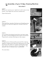
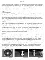
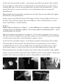
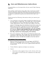
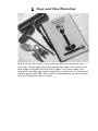
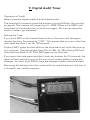
Maintenance and
Maintenanceand
and
Maintenance
Troubleshooting
Troubleshooting
Troubleshooting
User Manual
UserManual
Manual
User
Tel. (905) 448-5908
(905)
448-5908
Tel.Tel.
(905)
448-5908
Hi-Spy Viewing Machines
Hi-Spy
Viewing
Machines
Hi-Spy
Viewing
Machines
www.hispyviewing.com
CONTENTS
A. Assembly
B. Care and Maintenance
C. Usage and Care of Keset coin door locks
D. Troubleshooting Coin Viewers
E. Keys and hex wrenches
F. Digital Audit Timer
G. Freeplay on Coin Models
(Helpful videos are available on our website
under Customer Center on homepage)
A. Assembly of your Hi-Spy Viewing Machine
Standard
STEP 1
When you receive your machine it will come in two
boxes: one large box and one smaller box.
Open the boxes.
STEP 2
The small box contains the base and standing ring
already built and the large box contains the built
viewer.
STEP 3
You will also find three short bolts with two washers each in the package at the bottom of the box.
These bolts connect the base to the viewer.
STEP 4
Using a piece of the packing around the viewing
head to support the tube, turn the base on its side
at bottom of viewer as in Photo Assembly 4 and
bolt viewer to base as in Photo Assembly 5. Two
people, one to steady tube, is preferable.
You are done.
Dual
You will receive three (3) boxes. The large one contains the main tube with
the ADA arm attached and also the 12” base with its bolts. The other two
boxes contain each of the completely built viewing heads.
Assembly is easy and straightforward. Follow these steps:
STEP 1
Open large box.
Take out the small 12” base and its accompanying bolts (3 plus washers).
See Photo 1 showing small base.
Bolt small base onto bottom of main tube through bottom side of small
base. The lock washer goes onto bolt first, then the flat washer before you
do up each bolt.
STEP 2
Now that you have attached the base you will appreciate that with the viewing heads in place the unit is heavy to the one side and will fall over unless
you either:
a) place weights on base (40-50 lbs) on opposite side from ADA arm or
b) install the tube with base as is and then install heads at final location
– we recommend this one since it is very easy to install heads and it is
easier to handle tube without heads attached.
STEP 3
Once tube is upright and either weighted or installed you can install the heads.
Open the two remaining boxes. Each has a complete head. If the heads
you ordered were different from each other (example a 10X bino and a
20x bino) please select the one for the main tube accordingly and make
sure the head you want on the main tube is selected first.
Take the head out of the box. On bottom of head unit is a spindle that will
be inserted into spindle socket on top of main tube and locked in place
with a spindle bolt. See Photos 2 and 3 below of spindle on bottom of
viewing head and the cut-out.
PHOTO 1
PHOTO 2
PHOTO 3
Look into the spindle socket – see where spindle bolt enters the socket.
The spindle on the bottom of the head must be placed in such a way in
socket that the cut-out on spindle lines up with the spindle bolt – since
once that bolt is secure into the cut-out the head cannot come off.
See Photo 4.
Place head and its spindle correctly into socket. Secure spindle bolt tightly.
See Photos 5 and 6 below.
Lastly cover spindle bolt hole with larger of two cover plates. Holes are
bored. Use rivets and rivet gun provided to rivet on the plate to cover
hole. See Photo 7 and 8 below.
STEP 4
(Refer back to photos in Step 3 — only difference is smaller screw instead
of bolt and it is already in place – but may need to be backed off — and
smaller plate for cover)
Take the remaining head out of the box. On bottom of head unit is a spindle that will be inserted into spindle socket on top of ADA arm and locked
in place with a spindle screw (already in place in arm.
Look into the spindle socket – see where spindle screw enters the socket.
The spindle on the bottom of the head must be placed in such a way in
socket that the cut-out on spindle lines up with the spindle screw -since
once that screw it is secure into the cut-out the head cannot come off.
Place head and its spindle correctly into socket. Secure spindle screw tightly.
Lastly cover spindle screw hole with smaller of two cover plates. Holes are
bored. Use rivets provided to rivet on the plate to cover hole.
PHOTO 4
PHOTO 6
PHOTO 5
PHOTO 7
PHOTO 8
B - Care and Maintenance Instructions
Congratulations on the acquisition of your new Hi-Spy Viewing
Machine!
Your viewer is built to last many years with a minimum of main tenance required. However, there are a few care and mainte nance items listed below that should be performed periodically
in order to maximize the uptime and service life of your ma chine.
Please review the following information when you receive your
machine.
1. Coin machines come with three t-handle hex wrenches and
two keys (both in duplicate). The smaller key is for the head
lock (a pop-lock) on the underside of the head. This lock
covers a bolt which comes out with the smaller (3⁄16ths) hex
wrench. The larger key is for the Keset lock which covers the
bolt in the coin door. Take the lock out and use the larger
(3⁄8ths) hex wrench to open the coin door. The long hex
wrench is for the the four bolts holding in the coin acceptor
(in machine). Please read carefully the care and use of the
Keset lock which is attached. These locks are excellent
but they need to be used properly and tenderly.
2. Non-coin machines come with on t-handle hex wrench and
one key (in duplicate). The smaller key is for the head lock (a
pop-lock) on the underside of the head. This lock covers a
bolt which comes out with the smaller (3⁄16ths) hex wrench.
All machines (Coin and non-coin):
t
Remove head lock and door lock and spray with WD-40
lubricant or equivalent every 6 months. (3 months in harsh
environments). NOTE: do not use a grease based lubricant
on door lock.
t
Check all bolts, tighten and adjust as necessary.
t
Lenses:
>
Clean binocular eyepiece lenses with soft dry cloth only.
The surfaces of the lenses are coated and can be easily
damaged.
>
Clean large outer lenses of head with soft cloth and water. Do not use harsh dete
rgents as this can make them
permanently foggy.
>
NOTE: If moving machine from a cool location to a
warmer location the lenses may get temporarily foggy
on the outside of the lenses (even with waterproof
optics). This is just condensation on the outsides of the
lenses and will clear itself as temperatures equalize.
t
Apply anti-seize lubricant on door bolt on the inside of door
annually.
t
If removing the viewer or step ring from the base of the
machine for any reason, apply anti-seize lubricant to threads
before re-assembly.
t
DO NOT use WD-40 on viewing head bearings for up and
down movement.
These are permanently greased and WD-40 will wash away
the lubricant that already exists.
t
If required use touch-up paint (we sell both black and silver
for the heads) to cover any nicks and scratches on powdercoated surfaces.
t
(Coin only) Changing batteries - Four AA batteries are in a
battery pack on wire descending to bottom of tube. Battery pack is usually taped to circuit board which is encased
in black plastic. To ensure a good battery contact and to
stop corrosion at contact in battery pack, apply a little
dilectic grease (especially made for this purpose) to each
contact - both ends of each battery.
t
Rubber stops in viewing head. Whenever you open viewing
head be careful not to lose the two stops in each trunnion
in viewing head. They stay in place better with a dab of
white grease. If you need more we have them available.
C - Usage and Care of KeSet High Security
Locks
All Hi-Spy coin-operated viewing machines come equipped with
Keset high security locks on the coin access door. Keset locks
require precise treatment when being operated. It is important
to maintain inward pressure on keys at all times. Never force any
key into a lock or forcefully pull on any key with hands, key ring,
or any other instrument. Read these instructions carefully. Failure
to follow these instructions could cause lock to become inoperative.
1) All Keset locks provided by Hi-Spy are of counter-clockwise rotating movement, as shown below, and are shipped
already programmed such that for normal service only the
silver service key is required.
2) To unlock the door, insert silver colored service key with
notch on key head (as shown below) aligned with dot on
lock. Maintain slight pressure on key while turning counterclockwise to the unlocked position and gently slide lock
outward from its holder. NOTE: key is retained in lock at this
position. Do not try to remove key from lock while in this
position or damage will occur.
3) To lock the door, slide the lock and key back into the lock
holder in the door with the dot at the 9 o’clock position.
Maintain slight pressure on key and turn to the 12 o’clock
position and remove key gently from lock.
1FSJPEJDVTFPG8%PSFRVJWBMFOUJTSFDPNNFOEFEGPS
spraying into lock and onto the cam at the rear of the lock.
D - Troubleshooting Mechanical
Coin Viewers
Note there are only four components : battery, coin acceptor,
circuit board (encased in black plastic) and shutter
When troubleshooting a mechanical coin acceptor (Beaver)
viewer follow these steps every time :
Note: When testing, always listen closely for the noise the
shutter makes. This will always tell you something and help in
troubleshooting a problem.
Error 1:
If the shutter is not opening when a coin is cranked though the
coin acceptor (no shutter noise at all):
ALWAYS PROCEED IN THIS ORDER
- First: check battery voltage (replace batteries that
read below 5.7V). I f it’s reading close to zero, it’s
probably the batteries not making good contact
within the battery holder. Push each battery with
your fi ngers in the direction the spring is trying to
push them, and recheck voltage. In some cases you
may need to wrap electrical tape tightly around the
ends of the battery case to hold the ends of the
battery holder against the battery terminals, or try
a different battery holder. Reconnect battery pack,
and Re-test. Also check all the connections -reseat
them if necessary.
-Second: (this should only apply to a new machine
when it fi rst arrives- once connections are correct
they should stay correct): when you open the coin
door you will see two sets of connections. One
comes from the coin acceptor to the control board,
and the other comes from the shutter to the control
board. Swap these two sets of connections. Re-test.
(If no change, immediately put the connectors back
to the way they were previously. The wire colors are
meant to match up with each other when plugged
in correctly, though there are a few machines out
there where this isn’t the case.)
-Third: Try another control board
Error 2:
If you hear a noise from the shutter at cycle start, but nothing
is moving:
8BJUGPSNJOVUFTGPSDZDMFUPUJNFPVUBOEXBUDI
to see if it opens w hen the cycle fi nishes (this w ould
CFBOFSSPS
*GJUEPFTSFWFSTFUIFDPOOFDUPSTPO
the shutter w ires inside of the head.
Error 3:
If you hear a noise from the shutter at the start AND end of the
cycle, and nothing is moving:
4FSWPJTQSPCBCMZCSPLFO3FQMBDFTIVUUFS
Error 4:
Check t he operation of the micro-switch on the coin acceptor.
The micro-switch is a little bl ack plastic sw itch on the back si de
PGUIFDPJOBDDFQUPSXJUIBMFWFSPOJUBOEUXPXJSFTDPNJOH
GSPNJU1SFTTMFWFSXJUIZPVSmOHFSTBOETFFJGTIVUUFSPQFOT*G
UIFNBDIJOFXPSLTCZEPJOHUIJTCVU/05CZDSBOLJOHBDPJO
UISPVHIJUUIFOUIFDPJOBDDFQUPSOFFETUPCFSFQMBDFECFDBVTF
the micro-switch is then not bei ng activated by t he coin (and it
should be)
E - Keys and Hex Wrenches
Photo shows two sizes of t-handle hex key (hex wrench) and
two sizes of keys plus key fob. Larger key opens coin door lock
and larger t-handle hex key(3/8”) o pens coin door after lock
removed. Smaller key opens head lock ( underside of head) and
smaller hex key(3/16”) r emoves bolt revealed by removing that
lock and allows access to head.
F. Digital Audit Timer
Operation of Audit
Here is how the digital readout audit board works:
The board will constantly show the number of coins/bills/etc the unit has
accepted. This number will range from 0 – 9999. When it hits 9999 it will
cycle back to 0 and start the count all over again. No one can reset the
audit or make it go backward .
Setting the Time
If you push SW2 on the board( lower button), the menu will change to
display the time. For example: “t100”. This means that you are in the time
menu and the time is set for 100 seconds.
Pushing SW1( upper button) while in the time menu will cycle the time up
by 5 seconds. The time ranges from 30s to 180s. At 180 pushing SW1 will
cycle the time back to 30. Push SW2 again to set the time.
If you are in the time menu and don’t push any buttons for 2.5 seconds, the
menu will exit and return you to the coin count screen without saving any
changes. You must push SW2 to save the changes made in the time menu.
Removing the battery from the system will not cause the time to be lost. It
is stored in non volatile memory
G. Freeplay on Coin Models
Freeplay: On coin models if you wish to change unit to freeplay
(no money required to open shutter) simply do one of the two
following methods:
1. A) Open coin door.
B) Activate coin acceptor switch either with a coin or by
pressing switch contact inside on back of acceptor
C) When shutter opens disconnect battery so it cannot close
D) Close coin door
Now in freeplay.
OR
2. A)
B)
C)
D)
Open head
Manually move shutter to open position
Open coin door and disconnect battery
Close coin door
Now in freeplay.