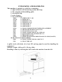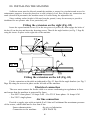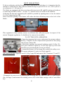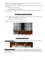
1
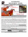
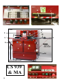
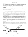
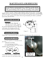
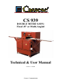
CS 939
DOUBLE MITRE SAWS:
Fixed 45º or Multi-Angled
Technical & User Manual
Version 6 of 12/2002
Cassese / Communication
AUTOMATIC
MEASURING STOPS
NUMERIC QUICK-STOP & SMART-STOP
USER FRIENDLY TOUCH SCREEN
(Keyboard)
NUMERIC STOP
(goes to requested size automatically)
QUICK STOP
+ Thickness Measurer
=
SMART STOP
Electric box of automatic stop - with CS 939 saws only
Both automatic stops can be ordered as an optional equipment with Cassese double mitre saws and will be
produced together with the saw at factory. Presenting an important gain of time compared to all manual measuring systems -sets itself up in just a few seconds, Cassese automatic stops make the operator also avoid mistakes,
thus sparing a lot of moulding and money. Available in 2 versions, their most important features are :
QUICK STOP
Customises in a Memory FILE up to 800 articles that are either profiles with their specifications or finished
products, i.e. a frame with the profile + its specs + dimensions of frame. ¤ Memorises up to 80 standard frame
formats –sizes of frames. ¤ Keeps in memory and puts automatically the regular play (allowance) for inside
(rabbet) measures ¤ Can work at any time with inside or outside measures but if customer is never using outside
measures, this can be “locked” to avoid operator mistakes. ¤ Can go at any time from short to long size of
frame.¤ A counter shows at any time the total cuts made and can be just reset for use as Counter of Chops when
cutting a series work. ¤ Very simple, user-friendly keyboard that can communicate in several languages to be
chosen on the screen.
SMART STOP
Includes all possibilities of QUICK STOP (see above). ¤ includes in more an Automatic Thickness Measurer on
the left hand side of the saw where the moulding comes into cutting machine to measure instantly the rebate
(rabbet) thickness of the moulding to be cut. Just by pressing on the keyboard to confirm the thickness measured,
the stop goes instantly to the dimension required. ¤ Brings to almost NIL all operator mistakes and moulding
waste. ¤ The more often you are changing mouldings in your production –custom framing, chop service etc-, the
better is this version for your operation.
TECHNICAL DATA
Power Supply :
Measuring capacity :
Options :
380 – 220 V single or three phased connected directly to the double mitre saw.
minimum outside : 120 mm (4”3/4), minimum inside depends on profile’s width /
maximum outside : 2060 mm (81”1/8) which makes maximum inside 1800 mm
(70”7/8) for the thickest 130mm (5”1/8) large moulding
to be chosen from the start : Metric or in inches / Extra longer construction for bigger measure
capacity / bar code scanner & wand / Connection to PC
O
O’
FIG2
FIG1
B
N
N’
M
M’
FIG3
U
S’
B’
C’
10
X
B
C
C
S
SC
E
b
J
b’
Y
ANGLE
BRACKET
Z
M
V
ANGLE BRACKET
CS 939
& MA
B
FIG4
D
I
F
G
L
A
K
CS 939 & MA PARTS LIST
A
B
B’
C
C’
D
E
F
G
I
J
K
L
O
O’
N, N’
M, M’ Fig1
Control button of safety cover lock
Left vertical clamp handle
Right vertical clamp handle
Left horizontal clamp handle
Right horizontal clamp handle
Control button left clamps & cutting
Control button right clamps & cutting
Control button retractable stop
Start-up of the saw blades
Control button left and right clamps & cutting
General isolating switch
Blades Off button
Safety cover lock indicator
Regulator of speed of advance motion of left blade
Regulator of speed of advance motion of right blade
Selection of left blade cutting angle
Selection of right blade cutting angle
M fig3 Pressure reducer
10
Fixed stop
S
Right extension
S’
Left extension
U
Opening cover
V
Waste drawer
X
Interior light
Y
Pneumatic system control cabinet
Z
Electrical control cabinet
b, b’ Bolt with triangle 11 mm LEGRAND ref. 365.41
SC Safety cover locking mechanism
C
CS 939 AIR LINE FITTINGS
Advised way of fitting :
USA
STANDARD
Male Connector
On Machine
Z 675
Z 675
Quick release (Q/R)
female air connector
Z 749
Q/R US male
connector
Standard hose
connector
Z 701
Z 556
AIR SOURCE (compressor)
D
I-
INTRODUCTION
The saw CS 939 is a machine for cutting:
- 45º mitres (45º version)
- or multi-angled mitres: 45º, 30º, 22.30º (MA version)
of all wood-based mouldings, whether solid or reconstituted wood,
untreated or coated (with paint, varnish, plastic, paper, etc.).
This does not include:
. Moulding profiles that do not have a 90º heel on a minimum height
of 5 mm,
. Any metal profile,
. Thin extruded plastic profiles:
(thin strip, linings, etc.).
Its two circular blades are driven by two electric motors.
The moulding is held in place automatically by vertical and horizontal
pneumatic cylinders.
A two-hand control acting simultaneously on the clamping and the cutting,
preserves operator safety by keeping the operator’s hands out of range of
the blades.
The electrical control components are installed in a cabinet on the right side
of the machine.
The pneumatic components are installed in a cabinet on the left side of the
machine. The connection is fitted to the base of the machine, outside the
cabinet.
Since this machine has been designed and constructed to meet the obligations of safety and hygiene, modifications to the electrical and pneumatic
components, the dismantling of the original guards supplied and modifications to the machine’s safety devices are strictly forbidden.
The CS 939 saw cannot be used by more than one operator at a time.
Residual risks
Under no circumstances are the hands to be placed inside the upper
protective cover beyond the plastic screen because of the presence of
the supporting cylinders and the rotation of the saw blades in their
Off position.
1
II-
TECHNICAL CHARACTERISTICS
DESCRIPTION
Year of construction
Cutting capacity:
max. width (overall)
(See page 7)
max. height
Blade dimensions (outside Ø)
Bore
Power supply (50 / 60 Hz)
CS939
1994
130 mm
90 mm
300mm
30mm
230 V
single-phase
230 V
three-phase
400 V
three-phase
Machine power consumption
30 a
16a
10a
Blade rotation speed (rpm) at 50 Hz
3400
3400
3400
Blade rotation speed (rpm) at 60 Hz
4125
4125
4125
Maximum length of cut:
1750 mm
Feeder cable standard (Section 4x 2.5)
H07 RNF 4G2.5
Extraction connectors (outside Ø)
2 x 100 mm
3
Extraction type conforming to standards:
28 m /s at 4 m for Ø 100
Pneumatic power supply (connection by Q/R connector)
5 to 7 bar
Consumption:
13NI / cycle (at 6 bar)
Weight:
499 kg (45º), 536 kg (MA)
Overall dimensions
Length:
3100 mm
Depth:
855 mm
(45º)
1080 mm (MA)
Height:
1350 mm
CS 939 45º & MA
1 left extension with moulding guide
1 right extension with moulding guide
1 pneumatic retractable stop
Accessories
Tool box / wheel-mounted waste drawer
Special cutting stop for small sizes
CS 939 45º & MA
1 left extension with moulding guide
Numeric stop option
Left measuring system, numeric, motorised
Airborne noise at the workstation
Sound pressure
Level:
Value:
Sound pressure:
< 70 dB
<63 Pa
<85 dB
CS 939 OPTIONS (45º & MA)
Extraction unit / Measuring extension
Numeric, motorised stop / Rebate measurer
Special horizontal clamps for small mouldings
Automatic moulding detection.
2
UNPACKING AND HANDLING
This machine is packed in a solid box containing:
- 1 right extension with measuring system and stop.
- 1 left extension with moulding guide.
- 1 retractable stop.
- 1 waste drawer.
- 1 box containing:
Z6012
Z11701
Z1348
Z1871
Z1879
Z1884
Z1885
Z2724
Z556
Z674
Z701
Z749
Z944
Z9522
2 x SCREW CHC 5 x 80
1 x WRENCH 32
1 x WRENCH 8 x 10
1 x WRENCH 10 x 13
1 x ALLEN KEY 2.5
1 x ALLEN KEY 4
1 x ALLEN KEY 5
1 x SMALL FORMAT STOP FINGER SUB-ASSEMBLY
1 x GROOVED END PIECE M 91/4 CYL
1 x GLASS FUSE 1.25 A 5 x 20
1 x MALE CONNECTOR US M ¼ TEFLON
1 x QUICK RELEASE CONNECTOR F 1/4
1 x PRESSURE GAUGE
1 x WRENCH WITH MOULDED TRIANGLE 8 MM (PLASTIC)
- In the electrical control cabinet:
Z540
Z703
1 x MALE CONNECTOR 20 A 380 V3P+T
1 x NEON TUBE 6 W
A pallet truck with forks of at least 155 cm long must be used for handling the
equipment.
Machine weight: 499 kg (45º), 536 kg (MA).
Handling is done by inserting the forks under the machine from the left.
3
III- INSTALLING THE MACHINE
Sufficient room must be allowed around the machine to ensure free circulation and access for
maintenance purposes. It must be placed on a solid, relatively level floor. Before any connections are
made (electrical & pneumatic) the machine must be levelled using the adjustable feet.
Since working surface height is 900 mm from the ground, it may be necessary to provide a
duckboard for an operator who is not particularly tall.
Fitting the extension on the right (Fig. 02)
Insert the square-headed screws (P) in the rear groove of profile (R) then engage the holes of
the bar (S) on the pins and insert the fastening screws. Then fit the angle bracket (see Fig. 3 Page B)
using the screws in place on the right side of the machine.
fig. 02
Pins
fig. 03
Fastening screws
Moulding
Fitting the extension on the left (Fig. 03)
Fit the extension on the table as indicated in Fig. 03, then fit the angle bracket (see Fig. 3
Page B) using the screws in place on the left side of the machine.
Electrical connection
The user must connect the feeder cable to a source conforming to regulations in force
and ensure that the machine is protected by fuses:
- For 400 V three-phase: 10 Amps A.M. - For 230 V three-phase: 16 Amps A.M.
- For 220 V single-phase:
Air line connection
Provide a supply pipe with an inside Ø of 8 that will withstand the maximum pressure
of the source, which must not be less than 6 bar.
Source characteristics:
dry air, no lubrication
Connection to the machine:
(SEE PAGE D)
4
DUST COLLECTION
To be in conformity with the European safety regulations in work place, it is imperative that the
machine is connected to a dust collector which develops a speed of 28 m / sec. (30.62 yds/sec.)
on a diameter of 100 mm (4”).
The blades are equipped with their own dust collection circuit (B1 and B2) joining each other at
a connecting box BR (2 holes 50 mm / 2”) located at the rear inside of the machine.
Collecting the dust non captured by B1 and B2 is possible by opening more or less the shutter
V of the connecting box BR.
Please note that opening of the shutter will reduce the dust collection power at the level of the
blades.
BR
Vis
B1
B2
V
This equipment of the machine insures an efficient dust collection system in respect of the
current European regulations. It should not be removed or modified.
C1
C2
CS 939 MA
ONLY FOR CS 939 MA:
IV- PUTTING INTO OPERATION
- Open the compressed air source and actuate the pressure reducer
M (Fig. 3 Page B). Set the compressed air pressure to 6 bar (using
the pressure reducer M).
- Switch the machine on (general isolating switch J) (Fig. 03).
The green indicator lights up. It will only light up if air and
electricity are present and the covers are closed.
- Actuate the button (A) (Fig.4 page B) to unlock the safety cover.
The green indicator (L) goes out (Fig.4 page B).
Open the cover U (Fig.3 page B) and remove the 2 retainers C1 and C2.
.
CS 939 MA
CS 939 45°
Z1 Z2
LOCKING
SCREW
CHC 5x80
LS
LS
Fig 04
- Dismantle the rear cover by removing the securing nuts (Z1 and Z2) with a 10 mm wrench
(Fig. 04 Page 5) and remove the locking screws (LS) of the blade carriage with a 5 mm Allen
key.
5
- Reclose the cover and lock it by actuating the button (A) (Fig. Page B). The green
indicator (L) (Fig. 04 Page B) lights up.
- Press the button (G) (Fig. 04 Page B) and check the direction of rotation of one of the
two blades.
- clockwise for the left shaft
- anti-clockwise for the right shaft
If the direction of rotation is incorrect, switch off the machine and invert two phases on
the feeder cable.
CUTTING ANGLE (939 MA)
4 knobs located on the operator’s left are used to set the position of the 3 cutting angles:
- 2 knobs for the left blade (N & N’) (Fig. 01)
- 2 knobs for the right blade (M & M’)
The different positions of the 4 knobs MM’ & NN’:
N
N’
M
M’
CUTTING ADVANCE
The knurled knob (0) (Fig. 01) is used to regulate the speed of the advance motion of
the left blade.
O
O’
The knurled knob (0’) (Fig. 01) is used to regulate the speed of the advance motion of
the right blade. The speed of advance must be adapted according to the material to be
sawed (hardness, cross-section, coating etc.), the quality of the cut and the characteristics
of the blades used.
6
THE BLADES MUST BE STOPPED
DURING ALL SETTING OPERATIONS
All setting procedures must be carried out with the cover closed. They do not require
any intervention inside the machine. This instruction is intended to preserve the safety
of the operator, who must under no circumstance insert his/her hands inside the cover.
CUTTING CAPACITY CS939 & MA
ÿþýüûúúø÷ööõôóøûòûøõöõýñðïîíî
ÿÿ
ÿ
EXAMPLE
For a moulding with a height of:
60 mm (vertical axis)
the maximum cutting width is:
103 mm (horizontal axis)
ÿ
ÿ
ÿ
ýõóö
ÿ
ÿ
ÿ
ÿ
ÿ
ÿ
ÿ
ÿ
ÿ
ÿ
ÿ
ÿ
ÿ
ÿ
õö
ÿ
ÿ
ÿÿ
ÿ
ÿ
ÿ
103mm
CONTROLS OF THE VERTICAL AND HORIZONTAL CLAMPS
- Check that the cover is locked and the green indicator is lit. If not, actuate the button
(A) (Fig. 04 Page B).
- The controls of the vertical and horizontal clamps are outside the cover whereas the
clamps themselves are inside the cover. The window located on the cover and the cover’s
interior light ensure that the clamps are visible.
- Place the moulding on the worktable inserting it to the left of the machine, with the
rebate side facing towards the saw blades. Position the vertical and horizontal clamps in relation to the profile and the width of the moulding using handles B & B’ and C & C’ (Fig. 03
Page B). To ensure that cutting quality is obtained and the necessary safety conditions exist, it
must be ascertained at the time of clamping that the vertical and horizontal clamps do not
place the moulding in an unstable position.
a) To check this position, draw back the horizontal clamps (Fig. 07) and start the vertical clamps (Fig. 07) via the button (I) (Fig. 01). Check that the moulding is not tilted and that
the bottom of the moulding is well seated on the table. If no position of the vertical clamps on
the moulding proves to be satisfactory, cancel them by setting the graduated rule to (0). The
horizontal clamps only will be operational.
7
figure 07
Right vertical clamp
Left vertical clamp
Right horizontal clamp
Left horizontal clamp
b) Move forward the moulding’s horizontal clamps (to +/- 5 mm) and start them via the
button (I) (Fig. 04 Page B). Check that the back of the moulding is well supported on the
stops (W & W’) (Fig. 07). If not, draw back the horizontal clamps completely (Fig. 07).
N.B. It is essential to have at least one of the two types of clamps activated. If this is
not the case, it is strictly forbidden to proceed with the cutting of this moulding.
Examples of round or exaggeratedly misshapen mouldings or mouldings with no proper
heel, which must not be cut by the CS 939 and the CS 939MA.
8
SETTING THE CUTTING LENGTH
Set the position of the knobs (MM & NN’) (Fig. 1 Page B) to the required angle. (See
page 6).
The use of buttons D, I (Fig. 4 Page B) & E (Fig. 3 Page B):
- Holding down button (I) initiates the left and right clamping operations. Continuing
to hold down button (I) and holding down button (E) at the same time initiates the right and
left cuts.
- Holding down button (D) initiates the left clamping operations.
- Continuing to hold down button (D) and holding down button (E) at the same time
initiates the left cut only.
- Holding down button (E) initiates the right clamping operations. Continuing to hold
down button (E) and holding down button (I) at the same time initiates the right cut only.
FIRST CUT * (left cut)
- Start the motors using button (G) (Fig. 4 Page B)
- Insert the moulding from the left side until reaching the intersection of the blades that
is visible through the window in the cover.
- Hold the moulding with the left hand and immobilise it by initiating the left clamping
operations (vertical & horizontal) by pressing button (D) (Fig. 4 Page B) with the right hand.
- Hold down button (D) (Fig. 01) and press button (E) (Fig. 3 Page B) with the left
hand to initiate sawing on the left*.
To ensure that the hands are safe during the operating cycle, a maximum time delay of
3 seconds is permitted between the two actions. If the delay between the actions is greater than
3 seconds, the buttons must be released and the operation must be recommenced in the same
order to trigger a cutting cycle.
IMPORTANT:
*DO NOT CUT THIN STRIP
9
If, after a cut, the waste or remaining piece of moulding does not fall by gravity into the
waste drawer and is not accessible from behind the cover, the waste must be removed by
pushing it with the next moulding or with a stick. It is strictly forbidden to cut several
moulding lengths at a time piling them one in front of the other.
Under no circumstances must the operator insert
his/her hands inside the casing behind the curtains
The workstation must not be occupied by more than one person whilst the machine is
in use. This one person has responsibility for the controls.
The sawing operation (advance motion of the blades) is only possible with the horizontal and vertical pneumatic clamps activated and the saw blades rotating.
Releasing one of the buttons during the cutting process causes the blade in action to
move back and the buttons have to be released so that the cycle can be started again.
If the electrical circuit is cut off by accident, the blade in action moves back
instantaneously. Once the electrical power supply has been re-established, the motors will
only start up if the control button (G) (Fig. 4 Page B) is actuated.
In an emergency, press the red fist-operated blade stop button (K) immediately and
before any other intervention is carried out, cut off the voltage supply via the general isolating
switch (J).
10
DEPTH OF REBATE MEASUREMENT
fig. 09
Move the slide (H) (Fig. 09) on the right panel of the table
to the required dimension (M) for the depth of the rebate and
lock the handle (T) (Fig. 09).
Move the moulding (mitre cut on the left) onto the slide
(H Fig. 09). (This measurement can only be done on a
moulding cut to the selected angle on the left side) so
that the bottom of the rebate coincides with the
oblique section of the slide that corresponds to
the selected angle.
H
M
T
10
- Then move the stop (10) (Fig.
09b) into contact with the moulding
and lock its handle.
10
fig. 09b
- Loosen the handle (T Fig. 09) and withdraw the slide (H Fig. 09) from below the moulding
- The length stop is controlled pneumatically in such a way that it retracts in the case of short
mouldings to facilitate removal after cutting:
a) either automatically at the end of the cycle as long as button E (Fig. 3 Page E) is held down.
b) via button F (Fig. 4 Page B).
M2
Using the 2 stops
A fixed stop and a retractable stop are provided.
With this combination both a length and then a width can be cut without problem.
Actuate button F every two cycles to retract the width stop and have the fixed stop set
to the desired length (M2).
11
SECOND CUT
Right cut
- The moulding is in contact with the stop (10 Fig. 09b) and held with the right hand.
- Hold down the left button E (Fig. 3 Page B) to immobilise the moulding.
- Press the right button I (Fig. 4 Page B) for the cut to be made on the right.
Double cut
- Hold down the right button I (Fig. 4 Page B) to immobilise the moulding.
- Then press the left button E (Fig. 3 Page B) for the first cut to be made on the right,
followed by the cut on the left.
CUT ON THE END OF A MOULDING (RIGHT CUT)
The clamping and cutting procedures are visible thanks to the window and the interior
light. The operator must check that the left horizontal clamp is well engaged in the
rebate of the moulding and not, on the contrary, causing pressure on the end of the
moulding (see Fig. 10).
In the latter case, the operator must only carry out the clamping and right cutting
operations using button (E) and then pressing button (I) without releasing button (E).
It is advisable to proceed in this way for all ends of mouldings i.e. using buttons (E)
and (I)
N.B: If the “Moulding detection” option is installed on the machine, selection of right
cut / left cut / double cut is done automatically and the operator only needs to press
buttons E + I (Figs. 3 and 4 Page E)
Important:
Check the filling level of the waste drawer (Fig. 01) at regular intervals, in line with the
intensity of the work. To avoid impeding the mechanisms providing angular movement
of the blades, waste should not be allowed to accumulate above the drawer’s upper
limit.
figure 10
12
MAINTENANCE AND SERVICING
For all operations involving maintenance, adjustment or repair, put the
machine’s electrical and pneumatic circuits out of operation by switching
off the general isolating switch (J) (Fig. 01) and locking it with a padlock.
On button (A) (Fig. 4 Page B) being actuated to unlock the cover, there is a time delay
(approx. 30 sec.), which is set in the works to take into account, if necessary, a corresponding
wait for the blades to stop completely, before the inside of the machine can be accessed. When
the cover is open, starting up the motors and moving and adjusting the blades is prohibited
by the safety unit (Z11262).
’
CHANGING THE BLADES
IMPORTANT
- Turn knob A (Fig. 4 Page B)
- Open the cover (U) (Fig. 3 Page B)
- Cut off the power to the machine via
the general isolating switch J (Fig. 3 Page B)
on the right of the machine and lock the
switch by placing a padlock in the tongue.
Figure 11
Dismantling the casing
Unscrew the 2 nuts (Q and Q’) (Fig. 11) and pull out the front part of the extraction case.
CHC 5x80
Dismantling the blades
For this operation it is advisable to wear
gloves to:
- Manipulate the blades,
- To avoid catching the hands.
Use supplied locking screw CHC 5x80 to
immobilise the shaft (Fig. 12).
LEFT BLADE
Fig. 12:
inserting screw
CHC 5 x 80
RIGHT BLADE
Unscrew the nut with the supplied 32 mm
wrench, then remove the cap and the blade.
13
REFITTING THE BLADES
- Fit the blade (teeth in the direction of the cut), noting the direction of rotation
indicated on the case.
- Replace the cap, the washer and the nut, and tighten the latter, then:
Remove locking screw CHC 5x80
REFITTING THE CASE
The case must be refitted to enable satisfactory extraction of the sawdust.
Left blade
case
REAR PANEL
Z1 Z2
To dismantle it, remove the 2 nuts Z1 and Z2
with a 10 mm wrench. This panel must be in place
when the machine is in use.
14
SERVICING
This depends on the frequency of use. Operational basis 8 hours / day.
Cleaning: empty the waste drawer, clean the plexiglass window with a soft cloth.
Check the belts: every 3 months.
Sharpening of the blades: a good cut is the result of good sharpening.
We advise you to consult your dealer for this service.
TYPE OF BLADE RECOMMENDED FOR MULTI-PURPOSE CUTTING
Diameter
Ø 300
Toothing
LR positive 3°
Number of teeth
96
FAULTS
Body thickness
2.7
POSSIBLE CAUSES
Blades not turning.
Indicator L not lit.
- Check the safety chain (red indicators on panel), see
diagram on inside of electrical control cabinet door
- Motor circuit-breaker not activated
- Pressure poor (min. 6 bar).
- Isolating switch J not activated.
- Cover U not locked.
The clamps are working
but the blades aren’t
advancing
- Actuation of the two-hand control buttons > 3 sec.
- Blades not in motion.
- The waste drawer is too full and this is impeding
movement of the blades.
Poor cut
- Blades turning in opposite direction (2 phases
inverted)
- Blades poorly sharpened
- Moulding in an unstable position, moving during the
cut
- Small mouldings being cut without the small
moulding clamp option (see page 2)
In the event of any other problem, please contact your dealer
15