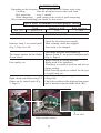
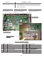
Download Manual - Cassese

Transcript
Z15009
CS 999
DOUBLE MITRE SAW
TECHNICAL AND USER MANUAL
MANUEL D’UTILISATION & TECHNIQUE
09/ 2004
Cassese Communication
AUTOMATIC MEASURING STOPS
CASSESE SMARTSTOP : DIGITAL AUTOMATIC MEASURING STOP
CS 999
Digital Stop
User-Friendly LCD Touch Screen
Automatic Width Measurer
0
The Cassese Smart Stop is an option which is available for the CS939, CS 939 MA & CS999 Saws. The special «Smart Stop» Saw
will have all of the features of the CS939 or CS999 Saw, but with a computerised automatic stop measuring system, available in Metric or in Inches.
The Smart Stop is designed for the high volume contract or chop-service framer, who likes to maximize productivity and minimize operator errors.
FEATURES OF THE CASSESE SMART STOP :
! User-friendly touch screen - tells the operator all information required to store or retrieve any moulding profile and/or frame size,
minimising mistakes and wastage.
! Fast setup time - The Smart Stop can be easily programmed to cut either a small photo frame or a large mirror frame in a few
seconds.
! Memorize your mouldings - The Smart Stop can be programmed to memorize the cutting process for up to 800 different
moulding profiles. Just enter the profile number, and the frame size, and the Smart Stop instantly adjusts its measuring stop to the
exact dimension, ready to cut.
! Memorize your frame sizes - The Smart Stop can also be programmed to memorize the dimensions of up to 80 different frame sizes.
You can set this up for all your standard frame sizes.
! Automatic width measurer - This instantly measures the rebate width of the moulding about to be cut, so that the cutting stop can
adjust itself automatically to the correct dimension required. It avoids any mistake of measurement and is much quicker than any
manual adjustment. Ideal for Chop Service.
! Odometer / chop counter - shows the total cuts made, and can be reset for use as a chop counter for big production jobs.
! Flexible - the operator can change between short and long sizes accurately, at any time, at the touch of a button.
! Minimise operator mistakes - Because of its memory and clear information readout on the touchscreen, operator error is reduced to
nil, saving waste, time and money.
! Multi-Lingual - The Smart Stop can operate in 4 different languages - English, French, German & Spanish.
OPTIONS:
! Bar code scanning system, including barcode editing software - for managing your moulding profile database.
! Connection to PC
! Bigger measure capacity on request
Cassese QuickStop : same features than SmartStop but without the Automatic Width Measurer
TECHNICAL DATA
Power Supply
: 380 – 220 V single or three phased connected directly to the double mitre saw.
Measuring capacity : Outside dimension : Minimum : 100mm (3'’ 9/10) Maximum : 1966mm (77'’ 4/10)
Inside dimension : Minimum : depends on moulding’s width (from 0mm to 100mm)
Maximum : 1800mm (with a 83mm wide moulding)
Options
: to be chosen from the start : Metric or in inches / Extra longer construction for bigger
measure capacity / bar code scanner & wand / Connection to PC
©2004 Cassese Communication
CS 999
Blade height adjuster
Blade height locking handle
Main case
Left vertical clamp locking handle
Right vertical clamp locking handle
Right vertical clamp
Left vertical clamp
Blade protection screen
Moulding guide
Left table
Right table
Right table set square
Left table set square
Main isolating switch
Offcut outlet
Electrical cabinet
Electrical cabinet door
Main case handle
Pressure regulator
Extraction air intakes
Main isolating switch
Numeric stop connection
(OPTION)
220 V electrical socket
for dust collectorv
Foot locking nut (x4)
Levelling foot (x4)
A
TECHNICAL SPECIFICATIONS
PRODUCT NAME
CS 999
Year of build 2004/2005
Cutting dimensions
Max. width
83 mm
Max. height
100 mm
Blade dimensions
Ø 350 mm
Bore
Ø 30 mm
Rotation speed
3400 rpm/mn at 60 Hz and 2800 rpm/mn at 50 Hz
Maximum cutting length
1500 mm
Electrical power supply
220/380 3-phase, 50-60 Hz
Power supply cable, standard, cross-section
4 x 2.5, H07 RNF, 4G1.5
2 power motors (compliant with standard EN 60204)
1.5 kW
Extraction air inlets, outer Ø
2 x 100 mm
Type of extraction compliant with standards
28 m3/s at 4 m for Ø 100
Pneumatic power supply
6 bar
Max. power consumption
700 cuts/hour 60 NL/mn at 6 bar
Weight
770 kg
Noise
(wearing of earmuffs compulsory)
90 dB
Options:
Right extension arm:
- Z14836: 2 metres
- Z14835: 0.78 metres
Numeric measurement stop* (on request / factory adaptation):
- Z14432: Smart Stop
- Z14431: Quick Stop
CUTTING CAPACITY
(HORS TOUT)
with max width = 83mm
100
90
H
E
I
G
H
T
*
80
70
60
50
* EXTERNAL
40
30
20
10
0
mm
1 0 2 0 3 0 4 0 5 0 6 0 7 0 8 0 9 0 100
WIDTH *
B
Contents
DESCRIPTION OF CS 999
TECHNICAL SPECIFICATIONS
A
B
I
- INTRODUCTION
1
II
- CS 999 OVERALL DIMENSIONS
2
III
- UNPACKING AND HANDLING
3, 4
IV - SETTING UP THE MACHINE
- Setting up the left and right tables
- Electrical connections
- Pneumatic connections
- Extraction
5
5
6
6
6
V
7
7
7
- STARTING UP
- Control panel
- Two-hand control
VI - SAWING
- Adjusting the blade height
- Adjusting the clamps and cutting
- First cut on left
- Measuring the first piece
- Retractable stop
- Cutting the first piece
8
8
8
8
9
10
11
VII - MAINTENANCE AND SERVICING
- Opening the main case
- Opening the electrical cabinet block
- Removing / refitting the blades
- Replacing the martyr cube
- Replacing the offcut support bar
- Replacing the table edges
- Maintenance / troubleshooting
12
12
12
13
14
15
16
17, 18
LIST OF WEARING PARTS
18
TECHNICAL DRAWINGS AND PARTS LISTS
19
I - INTRODUCTION
Saw CS 999 is a machine used to cut 45° mitres on all mouldings with solid
or reconstituted wood base, and with or without coating (paint, varnish,
plastic coating, paper, metal leaf such as gold, bronze, aluminium, etc.).
It cannot be used for:
. Moulding profiles that do not have a 90° heel greater than 5 mm
in height,
. Any metal profiles,
. Thin extruded plastic profiles:
(plastic cords, trimmings, etc.)
Its two circular blades are driven by two electric motors.
The moulding is held automatically by vertical and horizontal pneumatic
cylinders.
A two-hand control, actuating both clamping and cutting, ensures operator
safety by keeping hands out of range of the blades.
The electrical control equipment is placed in a cabinet in front of the machine.
The pneumatic equipment is secured in the base of the machine behind the
electrical cabinet.
This machine was built to meet safety and hygiene requirements. It is therefore
forbidden to modify the electrical and pneumatic equipment, remove protective
equipment installed on delivery or modify the machine safety devices.
Saw CS 999 cannot be used by more than one operator at a time.
Residual risks
Hands must never be inserted inside the beyond the plastic screens of
the top protection cover as this section contains the pressure cylinders
and rotating saw blades in their high idle position.
1
Electrical connections,
220 / 380 V, 3-phase, 50-60 Hz
Electrical socket
for dust collector
CS999 OVERALL DIMENSIONS
Offcut outlet
Extraction air intakes, dia. 100 mm
Identification label
Air supply at 6 bar
Electrical cabinet
2
Right extension arm 2.00 m
Right extension arm 0.78 m
Clearance area
STANDARD CS 999 OVERALL DIMENSIONS
III - UNPACKING AND HANDLING
This machine is packaged in a crate containing
·
·
.
.
1 right extension arm with Slot base measuring system
EXCEPT FOR NUMERIC
STOP OPTION
+ Fixed stop + Retractable stop (Option: CS 999> S/N 68).
1 left extension arm
1 box containing
- one 10-mm Allen key (to remove blades)
- one 6-mm Allen key (to assembly tables)
- one 3-mm Allen key
- 1 triangular key
- 1 quick-fit coupling (fitted on the machine) / 1 barbed connector / 1 USA
connector / 1 quick-fit coupling (see page 6)
1 blade steadying handle
Fuses: 1.25 Amp aM - (2 Amp aM - 4 Amp aM with numeric stop option)
Using a screwdriver open the fasteners on the crate then remove the cover and its 4 sides.
Remove:
1) The left and right - hand arms (to the right of the machine)
2) Accessories box (to the rear of the machine)
3) The trimmings case (to the left of the machine).
3
Remove the suction tip. Using a cross-head screwdriver remove the wedges from the 4 legs of
the machine.
Handling: Use a fork-lift truck fitted with forks at least 115 cm long, taking care to position
them correctly below the frame: see below. Gross weight of machine: 770 kg.
CAUTION: TO MOVE THE MACHINE FROM THE PALLET TO THE
GROUND SET THE FORKS 330 MM APART. FOR THE OTHER
HANDLING OPERATIONS SET THE FORKS 550 MM APART.
CAUTION:
SAFETY
DISTANCE =
50 MM
Position of forks
centred on the
frame axis
Once the machine
is installed, remove
protection.
Fork insertion area:
80 mm between the
ground and the base
of the machine
330 mm
550 mm
fork-lift truck
4
IV - SETTING UP THE MACHINE
There must be sufficient clearance around the machine
to allow free movement and access for maintenance.
It must be placed on a stable and generally flat floor.
Before making any electrical or pneumatic
connections, level the machine by means of the
adjustable feet. Use a 24-mm open-end spanner for
locking nut CE and a 12-mm open-end spanner for
base B. Tighten locking nut CE firmly after adjustment
and levelling. As the work surface is 900 mm from
the floor, it may be necessary to install a platform for
operators of short stature.
CE
B
Assembling the left and right tables
B2
V1
V1
B1
V2
V3
V4
V2
Loosen screws V1, V2, V3, V4 with a 10-mm Bring the grooves of table stops B1 and B2 to screws
V1 and V2.
open-end spanner.
B1
V4
V3
CM
B1
V3
Slide stop B1 into screws V3 and V4 and against
the martyr cube CM. Retighten screws V3 and
V4 (10-mm open-end spanner)
V4
V5
V1
E
V2
Retighten screws V1 and V2 below the table.
Remove screw V5 (4-mm Allen key) from the
cylinder of set square E. Move set square E below
the table and screw the assembly in place with
screw V5.
5
Fitting the offcut outlet case
SORTIE CHUTE
Fit the offcut outlet case using screws C1
and C2 (5-mm Allen key).
C1 C2
Electrical connection
The user must connect the power supply cable to a source complying with the regulations in
force and protect the machine by fitting fuses: 10 Amp aM for 380 Volt 3-phase and 16 Amp
aM for 220 Volt 3-phase.
Air line fittings
Advised way of fitting :
USA
Provide a supply pipe with an
inside Ø of 8 that will withstand
the maximum pressure of the
source, which must not be less
than 6 bar.
STANDARD
Z675
Z675
Quick release (Q/R)
Z749
Source characteristics:
dry air, no lubrication
Q/R US male
Z701
Standard
Z556
AIR SOURCE (compressor)
Extraction
To conform to hygiene standards the machine must be connected to an extraction air intake
producing a maximum flow rate of 28 m3/second over a diameter of 100 mm. The circuit
comprises three intake ports 100 mm in diameter: one on each side (only one plug must be
connected) and one at the rear of the machine. This installation guarantees effective extraction
and must never by dismantled or modified.
6
V - STARTING UP
1
2
MD
- Open the compressed air source and adjust the
machine pressure regulator to obtain compressed
air pressure of 6 bar.
OFF
- Switch on the machine: main isolating switch at
bottom right of the machine (see drawing on Page
A). Indicator lamp V (Fig. 3, Page 6) lights up.
This indicator lamp only lights if the CS 999 is
MAIN ON/OFF SWITCH
PRESSURE REGULATOR
energised.
Press button 2 (Fig. 3, Page 6) and check the rotation direction of one of the blades, i.e.:
- clockwise for the left blade,
- anti-clockwise for the right blade.
If the direction is not correct, press button 3 (Fig. 3, Page 6), disconnect the machine and reverse the two phases on
the power supply cable.
ON
CONTROL PANEL
3
NUMERIC STOP OPTION
(Voir page 9)
V
MACHINE ON
2
START
BLADES
3
STOP
BLADES
V1
V3
V2
4
CANCEL RIGHT
CLAMP
7 BLADE VERTICAL
SPEED REGULATOR
The knurled knob controls
the blade lowering speed.
6 RESET
5 CANCEL LEFT CLAMP
UNLOCK COVER
Note : The blade lowering speed must be set
MACHINE READY
according to the material to be sawn (hardness,
cross-section, coating, etc.), the required cutting
quality and the characteristics of the blades used.
BLADE HEIGHT REGULATOR
V1 = MACHINE OPERATIONAL
V2-V3 = CLAMP CANCELLATION LAMPS
TWO-HAND CONTROL
4
D
D’
Buttons D and D’ activate a two-hand control. The time between pressing the two buttons must not exceed
0.5 seconds. This prevents any accidental triggering if one of these 2 buttons is locked. Note that when D
or D’ is released during cutting, the blades lift immediately. To restart the cycle, both buttons must be
released and pressed again.
7
VI - SAWING
A- Adjusting the height of the blades
Set key A to “blade setting”.
Press D and D’ (Fig. 4, Page 6) to bring the blades to low position. Place the
moulding to be cut on the cutting table. Holding rule R by its loop, release handle
M located on top of the cover. Set the blade height using rule R or according to the
height of the moulding. The rule indicates the maximum clearance height for the
moulding. Relock handle M. Check that the moulding passes correctly below the
blade protection screen E.
Turn key A back to “normal operation”.
Note : The blade protection screen (E) is set automatically according to the blade
height setting. The measurement on rule R is the height of the moulding to be cut
plus approximately 1 centimetre.
M
E
R
M
BP
B- Setting the clamps and cut
First the position of the vertical clamps must be set:
Place the moulding with the slot side facing the saw blades on the
work table, feeding it from the left side of the machine. Release
the handle (M), set the vertical clamp positioning arms (BP)
according to the profile and width of the moulding. Start up the
right clamp (for example) via button D (Fig. 4, Page 6) and check
that the clamp pressor does not tilt the moulding.
The back of the moulding must be pressed firmly against the stops and the bottom against the work
table. To be sure of obtaining good cutting quality and the essential safety conditions, the moulding
must be immobilised and completely stable. Repeat the test under the same conditions for the left
clamp using button D’.
Reglet β
C- First cut on the left: The right clamps (vertical and horizontal) must be cancelled by
pressing button 4 on the control panel (Fig. 3, Page 6). After the first cut, these clamps will be
reactivated. If this precaution is not taken, the clamps may push the moulding against the blade
instead of immobilising it. Place the moulding with the slot side facing the saw
blades on the work table, feeding it from the left side of the machine. Slide the
moulding against the moulding guide and
towards the cutting table, keeping the
offcut minimising knob MC pressed.
When the moulding comes to stop
position against the offcut minimiser
(MC’) it will be in the best position for
cutting with minimum offcut.
MC’
MC
8
Start up the blade motors via button 2 of the control panel (Fig. 3, Page 6), then use
buttons D and D’ (Fig. 4, Page 6) to actuate clamping followed by blade lowering. The
first cut is then produced.
Buttons D and D’ (Fig. 4, Page 6) activate a two-hand control. The time between
pressing the two buttons must not exceed 0.5 seconds. This prevents any accidental
triggering if one of these 2 buttons is locked. Note that when D or D’ is released
during cutting, the blades lift immediately. To restart the cycle, both buttons must be
released and pressed again.
D- Measuring the first piece (mobile stop)
MEASURING THE SLOT BASE (INTERNAL)
LOCKING SCREW
RULE
C
S
UR
CURSOR
OR
READING
POINT
Slide the CURSOR along the rule and lock it at the required dimension by tightening the locking
screw. Bring the moulding to the cursor so that the edge of the slot base coincides with the 45°
angle.
Keeping the moulding in
position, bring the MOBILE
STOP into contact with the
moulding and lock it. Remove
the cursor below the moulding.
Slot base measurement is now
complete.
READING POINT
MOBILE STOP
EXTERNAL
MEASUREMENT
Release the MOBILE STOP
locking handle. Slide it on the
rule until it reaches the required
measurement.
Be sure to measure using the
external rule in relation to the
punch mark on the mobile stop
block. The external measurement is complete.
LOCKING
HANDLE
9
PUNCH MARK
RETRACTABLE STOP
(Storing a second cutting point in the memory)
FOR THE SLOT BASE MEASUREMENT, USE THE SAME PROCEDURE
AS FOR THE MOBILE STOP (PAGE 9).
FOR THE EXTERNAL MEASUREMENT, USE THE SAME PROCEDURE
AS FOR THE MOBILE STOP (PAGE 9) BUT USE THE INTERNAL RULE.
Allows the measuring and cutting of two dimensions of the frame, at any time.
Fig A
Fig B
L
I2
R2
L
I1
R1
The Cassese removable stop is a positive stop, easy to retract, by a simple action on lever L.
It remains stable and without play both in engaged and retracted positions.
Measuring Scale
Each measuring stop is indexed (red mark Il 8c I2) which indicate which one of the two scales
(rules) is to be used with this stop.These scales are for direct read-off of outside measurements of
the frame. Sliding Removable Stop: R1 with I1 // Sliding Fixed Stop: R2 with I2. Figure A.
The special design of the removable stop makes all mouldings to be placed in the best
way against the measuring system of the machine, even if the moulding is twisted.
10
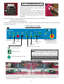
E- Cutting the first piece
The moulding is in contact with either the mobile stop or the retractable stop.
Press buttons D and D’ (Fig. 4, Page 6) for left and right clamping followed by blade
lowering.
END OF MOULDING
Clamping and cutting are visible to the operator. He must therefore check that the
horizontal clamp on the left is properly engaged in the moulding slot and does not create
pressure on the end of the moulding.
If it does, the operator can only continue with clamping on the right once the left clamp
has been cancelled via button 5 on the control panel (Fig. 3, Page 6).
Note: The left clamp will be automatically reactivated at the next cycle.
If the two-hand control buttons are kept pressed after cutting, the corresponding clamps
will not be released and the moulding ends or offcut can be retrieved without being
extracted to the offcut case.
If the offcut or piece of moulding does not drop under gravity after a cut, and cannot be
retrieved from outside the cover, it must be cleared by pushing with the next moulding
or a stick.
It is strictly forbidden to cut several lengths of moulding at the same time by lining them
up one in front of the other.
!
The operator must never put
his hands inside the case
When the machine is in use, there must be no more than one person at the workstation.
This person is responsible for the controls.
The sawing operation (blade lowering) is only possible with the horizontal and vertical
pneumatic clamps engaged and the saw blades rotating.
If one of the buttons is released during cutting, the blades are withdrawn but the clamps
remain engaged. The cycle can be restarted by pressing buttons D and D’ (Fig. 4, Page
6) or the cycle can be reset via key 6 of the control panel (Fig. 3, Page 6).
If the electrical circuit is accidentally broken, the blades are withdrawn immediately.
When power is restored, the motors will only start up when button 2 is pressed on the
control panel (Fig. 3, Page 6).
In the event of an operating problem, immediately press button 3 STOP BLADES (red
thrust button) on the control panel (Fig. 3, Page 6) and before taking any further action,
switch off the power supply at the main isolating switch (Fig. 1, Page 6).
11
VII - MAINTENANCE AND SERVICING
When the cover is open, motor start-up and blade lowering are
disabled by the safety unit
PROCEDURE FOR ACCESS INSIDE THE MACHINE
Opening the main case
- Press button 3 on the control panel (Fig. 3, Page 6) if necessary.
- Position the control panel key to “unlock cover”.
- Wait during the 20 second time-out until green lamp V1 (Fig. 3, Page 6)
goes out, indicating that the blades have stopped completely.
- Lift the locking levers of the 3 spring clips S1, S2 and S3 and release the
hooking mechanism.
- Using handle P, pivot the cover upwards and let it rest on the flexible stud at
the top of the machine.
!
For all maintenance, adjustment or repair operations, prevent unintentional
operation of electrical and pneumatic circuits on the machine by padlocking
the main isolating switch.
S1
P
S2
S3
Opening the electrical cabinet block
A
Open the door of the electrical
cabinet using the key provided
and remove screws A and B.
Tilt the cabinet by pulling it
towards you.
B
12
REMOVING THE BLADES
IMPORTANT
Switch off the machine at the main isolating switch (Page 6) located on the
right of the machine and lock the switch by padlocking the tab.
During this operation gloves should be worn to handle the blades and to
avoid getting yours hands caught.
Use the steadying handle provided to immobilise the shaft, loosen the nut (when
loosening the blade securing nuts always pull the key towards you), and remove
the flange and blade.
USING THE
STEADYING HANDLE
Steadying handle
10-mm Allen key
REFITTING THE BLADES
Clean the blades and flanges.
Fit the blade (teeth pointing in cutting direction). Check the cutting
direction carefully: it is marked on the support.
Refit the flange and screw then tighten the screw while holding the
steadying handle to immobilise the shaft.
Close the main case. Hook up the 3 spring clips and close their locking
levers, then switch on the main isolating switch.
Lock the cover by setting the key to Normal operation position.
13
REPLACING THE MARTYR CUBE
Open the main case (Page 11).
Loosen screw V1 using a 5-mm Allen key and remove the worn martyr cube by sliding it
towards the inside of the machine.
Refit the martyr cube so that a sound side is facing the blades and secure it with screw V1.
Close the main case. Hook up the 3 spring clips and close their locking levers, then
switch on the main isolating switch.
Lock the cover by setting the key to NORMAL OPERATION POSITION.
Start up the blades by pressing button 2 on the control panel (Fig. 3, Page 6).
Reduce the blade lowering speed using button 7 on the control panel.
Press simultaneously buttons 4 and 5 on the control panel (Fig. 3, Page 6), causing the
two cancellation lamps V2 and V3 to light up on the control panel (Fig. 3, Page 6) for 3
seconds. During this time, press buttons D and D’ of the two-hand control (Fig. 4, Page
6). The rotating blades drop to low position in order to machine the martyr cube. When
the two-hand control is released, the blades lift and the indicator lamps go out.
MARTYR CUBE
V1
THE MARTYR CUBE AND OFFCUT SUPPORT BAR CAN BE FITTED AND
MACHINED AT THE SAME TIME
14
REPLACING THE OFFCUT SUPPORT BAR
Open the main case (see Page 11).
Open the door of the electrical cabinet using the key provided and remove screws A and B. Tilt
the cabinet by pulling it towards you. (Page 11).
Next remove screw VTR (5-mm Allen key) and lower the setting rod of the offcut support bar.
Remove screws C and D (4-mm Allen key) and remove the worn offcut support bar (AS).
Refit a new bar on the setting rod and then reinstall the assembly (bar pressing below the martyr
cube). Lock the setting rod via screw VTR. Close the main case.
Hook up the 3 spring clips and close their locking levers, then switch on the main isolating
switch.
Start up the blades by pressing button 2 on the control panel (Fig. 3, Page 6).
Reduce the blade lowering speed using button 7 on the control panel.
Press simultaneously buttons 4 and 5 on the control panel (Fig. 3, Page 6), causing the two
clamp cancellation lamps V2 and V3 to light up on the control panel (Fig. 3, Page 6) for
3 seconds. During this time, press buttons D and D’ of the two-hand control (Fig. 4, Page 6). The
rotating blades drop to low position in order to machine the offcut support bar. When the twohand control is released, the blades lift and the clamp indicator lamps go out.
THE MARTYR CUBE AND OFFCUT SUPPORT BAR CAN BE FITTED
AND MACHINED AT THE SAME TIME
A
B
VTR
AS
C
D
AS
15
LIf the cut has defects such as tears of the paper coating (covered mouldings)
or splintering of the base (below the moulding) you must
REPLACE THE TABLE EDGES
Open the main case (see procedure on Page 11).
Switch off the machine at the main isolating switch located on the right side of the machine and
lock the switch by padlocking the tab.
Open the door of the electrical cabinet using the key provided and remove screws A and B (see
Page 11).
Tilt the cabinet.
Remove screws Vb1, Vb2 and Vb3 from worn table edges using a 4-mm Allen key.
Fit the new table edges on the cutting table. Close the main case (Page 13).
MACHINING THE TABLE EDGES
Start up the blades by pressing button 2 on the control panel (Fig. 3, Page 6).
Reduce the blade lowering speed using the knurled screw.
Press simultaneously buttons 4 and 5 of the control panel (Fig. 3, Page 6). This causes lamps V2
and V3 to light up on the control panel (Fig. 3, Page 6) for 3 seconds. During this time, press
buttons D and D’ of the two-hand control. The rotating blades drop to low position in order to
machine the table edges. When the two-hand control is released, the blades lift and the indicator
lamps go out.
BORDS
DE
TABLE
Vb1
Vb2
Vb3
REPLACING THE FILTERS ON THE ELECTRICAL CABINET
Internal ventilation of the electrical cabinet is required for the electronic cards and PLC to operate
correctly. The filters (ref. Z11258) placed each side of the cabinet must be replaced at regular
intervals.
16
MAINTENANCE
Depending on the frequency of use. On the basis of 8 hours work a day:
Cleaning
: clean the plexiglass screen with a soft cloth
Belt inspection
: every 3 months
Blade sharpening : good cutting is the result of good sharpening
We recommend contacting your dealer for this service.
Type of blade recommended for multi-purpose cutting
Dia. 350
FAULT
Teeth
3° positive LR
Number of teeth
108
Body thickness
2.7 mm
POSSIBLE CAUSES
- Check the electrical power supply.
Indicator lamp V on control panel - Main isolating switch not engaged.
(Fig. 3, Page 6) is off.
- Fuses need to be changed.
- The blades have not been started up.
The clamps operate but the blades - Buttons D and D’ not pressed simultaneously
do not lower.
(Fig. 4, Page 6)
- Blades turning in wrong direction.
Poor quality cut
- Blades need to be sharpened.
- Moulding in unstable position and moves
during cutting.
- Blade lowering speed not suitable for the type
of wood being cut.
- An offcut may be preventing the blades from
Right clamp cancellation lamp V3 lifting fully.
flashes on the control panel (Fig. - Check the condition of the high position sensor
3, Page 6).
and its distance from the blade block (BL).
BL
1.5 mm MAX.
High position sensor
17
FAULT
POSSIBLE CAUSES
Indicator lamp V1 is off.
COVER SAFETY DEVICE
Check that the main cover is
closed correctly.
Safety chain broken. Open the electrical cabinet and check
on the electronic card to see which item in the chain is
faulty (LED red lit).
THERMAL CIRCUIT BREAKER 2
Reset the thermal safety device. If it
trips again, call the After-Sales
service.
THERMAL CIRCUIT BREAKER 1
Reset the thermal safety device. If it
trips again, call the After-Sales
service.
STOP BLADES
Check the red STOP
BLADES button.
COMPRESSED AIR
Check the air supply.
THERMAL CIRCUIT
BREAKERS
LIST OF WEARING PARTS
QTY
2
1
1
1
1
2
2
Z CODE
Z843
Z14070
Z14830
Z14831
Z14832
Z1570
Z11476
PART NAME
FLEXIBLE STOP Ø20x8.5 - M6x15
SHAFT
CUTTING SQUARE
RIGHT TABLE EDGE
LEFT TABLE EDGE
BLADE Ø350 - 108 TEETH LR
BELT XPZ 710
QTY
1
2
1
1
3
3
3
1
18
Z CODE
Z14376
Z11257
Z555
Z1415
Z1688
Z1676
Z9542
Z674
PART NAME
OFFCUT SUPPORT ROD
VENTILATION FILTER + GRILL
FUSE, 2A 10x38 aM
FUSE, 4A 10x38 aM
RULE 0-500mm
RULE 0-1000mm
RULE 1000-2000mm
GLASS FUSE, 1.5A 5x20