1
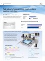
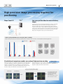
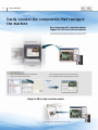
XPECTIA FH VISION SYSTEM F a s t e s t e v e r i n d u s t r i a l c o m p a c t v i s i o n s y s t e m » » E a s y t o i n t e g r a t e » »F a s te r m a c h i n e s p e e d » » H i g h - p r e c i s i o n m a c h i n e o p e r a t i o n 2 F astest* ever industrial compact vision system FHSeries Designed for use in all types of object inspection, position/orientation and measurement operations, this compact camera and controller system is easily integrated into almost any machine or robot. The system is uniquely capable of providing faster, more precise work throughput – to give you more efficiency, less cost, and more competitive advantage. A key feature of the system is its advanced new vision algorithm: Shape Search III. This advanced, intuitive program gives you higher-speed and greater precision Input measurement even with difficult imaging conditions such as poor lighting, out-of-focus and rotated/ randomly positioned/overlapping target objects. Specifically intended for seamless integration with PLCs, motion controllers, and robotics the FH Vision System meets the diverse needs of builders of highspeed manufacturing machinery. The system also offers the flexibility of a PC-based vision system for easy customization and HMI integration. * Based on Omron investigation in May 2013. Shorter machine cycle t 3 Faster machine speed High-speed image processing A high-speed image bus and 4-core processing increases speed at every step, from image input to data output. Multiple camera inspections Calculations are quick and easy for four parallel tasks to provide total judgement results. Fast output to PLC You can output results to an NJ Series machine automation controller on an EtherCAT communications cycle in just 500μs. High-precision operation Measure out-of-focus or rotated images The new Shape Search III processing item provides superior stability. Assured calibration accuracy No worker dependent calibration, vision master calibration is provided. Easy to integrate Shared machine interface Supports Microsoft®.NET Simplified interface Customizable user interface means only your required menu commands appear on the operation interface. Fast support for additional needs For additional measurement needs, complete processing item libraries are provided. Logic control times Positioning 4 FH Faster machine speed P rocess higher-resolution images without increasing machine cycle time Fastest: 3.3 ms High-speed image input Real-time image transfer Camera resolution continues to increase. That’s why Omron has greatly reduced the input and transfer times of high-resolution images - to provide high-speed processing that matches the speed of your machine. Even with more cameras and higher resolution, high-speed image input will help increase throughput. High-resolution cameras capture large amounts of data, which can cause transfer- and input-bottlenecks. That’s why the FH Series Controller provides a faster, multi-line image bus to enable real-time transfer of large amounts of image data even for multiple cameras. Now you don’t need to sacrifice precision to enable faster machine speed. 60ms Image transfer time Previous Camera 50ms 40ms 7 Times faster 30ms ith the FH Series, even if W the number of connected Cameras increases, realtime transfer of Camera images is still possible 20ms 10ms FH High-speed Camera 5ms High speed 300.000 pixels 1 million pixels 2 million pixels 3 million pixels 4 million pixels 5 million pixels Number of Cameras Note:The image conversion processing time is not included. Shape Search III Ultra-high-speed Searching ew technology makes search algorithms up to nine times faster than N before. Even for unstable image conditions (including light interference, overlapping shapes, gloss, and incomplete images), stable searching is now possible without reducing speed. Input Image Size FH-Series Realtime Image Transfer Time (ms) up to 9 Times faster 300.000 pixels 2.000.000 pixels 5.000.000 pixels Previous search processing items S hape Search III in Normal Mode S hape Search III in Fast Alignment Mode Note:The image conversion processing time is not included. P revious Controller with 5-million-pixel Normal Cameras F H Controller with 5-million-pixel Normal Cameras F H Controller with 4-million-pixel High-speed camera (High-speed mode using one cable) 5 FH F our-core CPU* for high-speed demands on different machines *for high-speed controllers only Machine cycle time reduced by 75%** Process multiple lines without waiting Four core process triggers, so the trigger interval can be 1/4 of previous models (in-house comparison). Four controllers are compressed into one without increasing the line cycle time. You can greatly reduce costs for processes that involve many lines. Process 1 S tandard Vision Sensors Process 2 Process 3 Process 4 FH-Series Trigger Trigger Reduced to 1/4 FH Process 1 Process 2 Process 3 Process 4 Line 0 Process 1 Process 2 Process 3 Process 4 Trigger easurement M processing I mage input easurement M processing Output Line 1 Trigger Trigger I mage input Output Line 2 Process 1 Process 2 Process 3 Process 4 I mage input easurement M processing I mage input easurement M processing Output Line 3 Multi-input function Continuous high-speed image capture Output Higher speed from advanced image capture and parallel measurements Each camera has its own image buffer for storing image data. This is separate from the main memory that is used for measurement processing. This allows for up to 256 frames of continuous high-speed image capture even when the main memory is processing measurement data. I mage input 1st Measurement processing 2nd 3rd 1st 4th 2nd * *The number of images that can be captured depends on the controller and the camera that is connected to it. Refer to the user’s manual for details. Movement of workpiece 3rd 4th Eliminate ‘waiting time’ bottlenecks 6 Faster machine speed FH F ast output of measurement results reduces machine cycle time EtherCAT machine control network Communications cycle EtherCAT is a high-speed open network that is ideal for machine control. You can use it to connect NJ Series machine automation controllers and motion control G5 Series Servomotors and Servo Drives to increase the control speed of everyday communications protocols from workpiece detection to starting axis motion. Conventional communications standard 4 ms 0.5 ms EtherCAT Reduced to 1/8 Time from trigger input to producing measurement results Features • Communications cycle as low as 500 μs Conventional communications standard • Motion control that’s synchronized with the communications cycle Shortened by approx. 6 ms. EtherCAT Note:The times given above are typical times. They depend on parameter settings. Positioning solution that eliminates workpiece dwell time: Patent pending F or a machine that requires micron precision, one alignment is not always enough to obtain the desired precision – multiple alignments are often necessary. But these extend the processing time. That’s why Omron provides control methods that eliminate workpiece dwell time, which is the main cause of increased processing time. Our Sysmac Automation Platform achieves high-speed, high-precision control that continuously detects workpiece positions and successively updates the travel distance to quickly approach the target position. NJ-series Machine Automation Controller G5-series Servomotors and Servo Drives Previous Vision Sensors easureM ment Stage Movement easureM ment Stage Movement easureM ment easureStage Movement M ment Stage moving speed T his graph indicates the speed changes in one specific axis (the X axis). easureM ment T he dotted box indicates the target precision range. Alignment Stage Movement Stage moving speed easureM ment easureM ment T he dotted box indicates the target precision range. easureM ment This graph indicates the speed changes in one specific axis (the X axis). The workpiece quickly approaches the target position without stopping. Alignment Note:Please ask your OMRON representative for details. FH FZ5 High-precision operation igh-precision image processing required for H positioning Shape Search III Low-error position detection even with blurry images Over many years, Omron has perfected techniques to search for and match templates at high speed. This experience and expertise enables us to develop the Shape Search III vision algorithm, which provides advanced robustness and is critical on FA sites. When measuring lamination of glass or other processes where the distance to the workpiece from the camera varies, size differences and focal shifts can occur. Even in cases like this, the new Shape Search III algorithm detects positions with limited error. Camera Glass 1 Glass 2 Stable searching with limited error even under adverse conditions Stable searching is possible even under the following adverse conditions, which occur far too often in actual measurement applications. Previous Search Shape Search Error (pixels) Focal shift Hidden Focal shift Contrast Chips Hidden Overlapping Contrast Chips Overlapping Thinning and thickening Thinning and thickening Visualization of comparisons enables easy setup of high-precision searching dvanced searching is accompanied by many parameters that must be tuned A to match the application. However, it is difficult for the person making the settings to see the internal process. Normally, a lot of time and effort is required to maximize tool performance. But with Shape Search III, you can visualize comparisons between the model data and a part of the Patent pending measurement object to easily see when comparisons are not optimally matched. Visualization of the comparison level allows for parameters to be adjusted to quickly obtain the best performance. ou can see at a glance the difference between Y the registered model and measurement image Registered model Measurement image eduction R incorrelation Deformation Chip o N Reduction ou can adjust a parameter called Y the Acceptable Distortion Level to enable measurements without reducing the correlation even if there is distortion. You can easily adjust this parameter while monitoring the comparison. 7 8 FH Easy to integrate E asily connect the components that configure the machine Easy integration into a machine monitor Support for .NET user interface controls Custom .NET controls are supported so that you can easily display FH Controller measurement images and measurement results on a PC. Integrated Machine Monitor FH Easy customization C ustom controls for FH measurement images and measurement results are laid out on Microsoft Visual Studio®. Instead of writing the program code from scratch to build interfaces, you can easily build the interfaces simply by pasting custom controls. Pasting custom controls Output to HMI or high-resolution monitor Microsoft® Visual Studio® is a registered trademark of Microsoft Corporation. FZ5 9 FH D esign components with one software Develop machine control programs with one software: Sysmac Studio Use the Automation Software Sysmac Studio to set up all of the slaves connected via EtherCAT. Simulate and debug motion control, logic, drives, and sensing on an integrated platform to reduce the work required for machine design. One Software Sysmac Studio version 1.07 or higher supports the FH Series. NJ-series Machine Automation Controller FH-series Vision System G5-series Servomotors and Servo Drives Minimized commissioning & adjustment Integrated simulations linked to an NJ Series Machine Automation Controller let you verify the NJ Series program logic. You can directly edit the EtherCAT I/O map to send measurement commands to FH Series Vision Sensors. 10 Easy to integrate FH FZ5 Easy setup with program scalability Customize original operation interfaces Show only the buttons you need hoose from our library of buttons and position them on screen to best support C your daily operation, without “screen clutter”. rrange the interface elements A flexibly ou can flexibly change the image Y display composition to display entire image, enlarge part of an image, or display images from different cameras. Move windows freely rag and drop windows where you D want. You can also change the box size and delete. Eight screen layout Up to 8 screens can be stored depending on the application or user classification. Freely Lay Out Dialog Box Contents Completed Hide unnecessary adjustment commands With only menu operations on the controller, you can customize the setting displays in dialog boxes for processing items. For example, you can set up the interface to hide any parameters from the user. nly a parameter required for O daily operation can be displayed. Completely different operation interfaces for designer and operator Accounts can be used to keep completely different operation interfaces for the designer and operator. You can set up to eight levels of security for up to 50 items for each account. You can record operation logs for each account to enable smoothly isolating problems when troubleshooting. Operating time Operating user Opertation FH 11 FZ5 Build measurement process with flowchart programming Just add any of the large variety of processing items to the measurement flow to build the basic program for image processing. All processing items have menus for easy setup and adjustment. This enables you to easily build the best imaging processing for each application and to smoothly complete testing and adjustments without programming. Flowchart J ust add processing items from the processing item list to visually edit the flow. Processing Item List Folders ou can group processing units into named Y folders. By managing related processing together and hiding lower levels, you can display even long measurement flows in a way that easily shows the overall flow. Flowchart Output You can save the flowchart as an image file. Branching ou can use conditional branching to branch according to the Y execution results of the previous processing units or you can use branching controls with external commands through parallel I/O, PLC Links, or no-protocol communications. Easy multi-language support: Choose any of nine languages Display the best language for the user for applications in other countries. You can change display messages between nine different languages: English, Chinese (traditional or simplified), German, French, Italian, Spanish, Korean, and Japanese. English Simplified Chinese Traditional Chinese Korean German French Italian Spanish Japanese 12 FH Vision systems Vision systems line up FZ5 Lite controller FZ5 standard controller FZ5 High-speed controller FH standard controller up to 4 cameras FH Ultra-high-speed controller up to 8 cameras Encoder input FZ5 FH FZ5 Processing item library H igh-precision alignment library F our specialized types of alignment calculations are provided. You can combine these to easily execute alignment calculations on the FH Series Vision System that require complex calculations on previous sensor models or computers. Alignment Calculations Movement Single Position Position Data Calculation Movement single position Movement multi points The axis movement that is required to match the measured position angle to the reference position angle is calculated. The axis movements that are required to match the measured position angles to the corresponding reference position angles are calculated. Convert position data Position data calculation The position angle after the specified axis movement is calculated. The specified position angle is calculated from the measured position. Movement Multi Points Convert Position Data Available alignment methods T he Position Data Calculation processing item is used to calculate the position and angle to use in the axis movement based on measurement results (shown in green). Position angle alignment Offsets are suitable for aligning the positions of workpieces with different sizes. Position angle alignment allows the use of offsets to achieve flexible positioning. T he rotational movement on the θ axis is calculated as the reference angle minus the measured angle. T he measurement position is rotated by the rotational movement for the θ axis (grey). T he reference positions X and Y minus the measured positions X and Y after rotation are used as the X-axis movement and Y-axis movement. Corresponding point alignment The axis movements from the measured positions to the reference positions are calculated based on relational position information. This method is suitable for aligning all points within certain distances so that small deviations in the distances do not result in continuity failures, such as they can when aligning electronic substrates. Reference positions Measured positions Maximum error ranges Corrected 13 14 FH Processing item library FZ5 I mage filter library Calculations between images Labelling filter You can perform arithmetic operations, bit operations, averaging, or maximum/minimum operations between two images. This filter uses label processing to output an extracted image that contains only the specified characteristic labels. External appearance of electronic components Library Previous vision sensors Labelling filter image Extraction is possible only with color or brightness information. Extraction of labels with specified areas or shapes is possible. Colour Grey A nti Colour Extract Filter Shading Colour Filter Background Suppression Filtering Custom filter Stripe Removal Filter II You can set the mask coefficients as required for these filters. The mask size can be up to 21 × 21. You can more flexibly set image smoothing, edge extractions, dilation, and erosion. Brightness PositionCompen- P olar TransCorrect Filter sation formation Trapezoidal correction+ Panorama Filter coefficients Example: Dilation/erosion in one direction Advanced Filter Before filtering After filtering You can set the filter coefficients as required. Advanced filter The image filter library has been condensed into one processing item. This allows you to easily set complex filtering as required for external inspections. Previous Vision Sensors Advanced Filter any different filter functions M can be set with just one processing unit. Application flow example Camera image input Camera image input Precise defect Advanced filter Labelling filter Camera image input nits were added for U each filter. Y ou set up to 16 of the 24 different filters. Erosion x 2 Mask Image Precise defect Precise defect T he averge image is obtained from multiple images. Advanced filter Calculation between images: Averaging Precise Defect Measurement image T he filtered image is used as the mask. FH 15 FZ5 U tility library Macro/ Macro Calculaction Macro Macro calculation The macros Macros let you easily achieve flow control that normally requires complex programming from the user interface. Improvements to the setup from the user interface provides ease of selection and modification of the programming process. Select the process to use Insert the process Set the parameters Registered images Reference Variable List Function Guidance V ariables can be used in macros to access processing item data and system data. F or example, it would previously have been long and complicated to change the set parameters of a processing item for each product model. With a Macro Calculation processing item, the flow is shorter and setting changes are easy to achieve. Previous Vision Sensors Easy to change FH/FZ5-series Macros J ust enter the values of the variables to update the parameters. Branching for each product model Select INDEX@ Case 0 ExtCond0@ = 1 ‚ Area ExtParam0@ = 0 ExtParam1@ = 10000 Case 1 ExtCond0@ = 4 ‚ Elliptic major axis ExtParam0@ = 0 ExtParam1@ = 100 Case 2 ExtCond0@ = 7 ‚ Rectangle width ExtParam0@ = 0 ExtParam1@ = 200 End Select 16 FH Utility FZ5 O peration and analysis Optimum operation both online and offline Connections to a network hard disk drive or network computer enables a wide range of operation possibilities. You can log measurement images long-term, or you can perform verifications and adjustments on a computer without stopping the FH Series. Online Onsite Operator Offline Designer Offline Setting Changes and Simulation Log images via Ethernet HUB Remote Operation C heck NG images on a computer at any time PC Ask your OMRON representative about obtaining simulation software. ew Operation Schemes through Network N applications Ideal for history management CSV files allow you to easily understand the parameter settings. Also, you can easily change any of the settings. Daily monitoring Comparisons Y ou can store NG image in a network HDD to check the NG images every day on a computer without reducing measurement performance. Or you can start simulation software on your computer to remeasure and analyse NG images. I f you save the basic settings, you can easily extract any differences in settings caused by changes made incorrectly. Periodic adjustments and inspection adjustments T he non-stop adjustment function lets you change Controller settings without stopping the production line. With remote operation, you can perform operations without going onsite. Handling unstable inspections or measurement failure T he user sends the programmer the image data, setting data, and parameter settings. The programmer can use the simulation software on the computer to check the process and change the settings with the simulation software. The altered scene data can be returned to the user and loaded to the system to complete the adjustments. This enables modifications without requiring the programmer to be on site. Adding inspections or making changes for new models B ased on the images to be inspected, settings are made on the simulation software on a PC running simulation software. The scene data is sent to the user to easily add the new settings. Remote adjustment Y ou can attach CSV files to email and upload settings to the FH Series Vision System to easily make adjustments from remote locations when problems occur. Upload Setting changes FH 17 FZ5 Remote operation centralizes monitoring and adjustment of scattered sensors You can check the status and adjust the settings of many FH on one computer. This enables efficient adjustment of Camera images when commissioning a system and application of test adjustment results. Operating several FHs from one location Application example hen commissioning a line, from one location you can adjust the camera images from all of the FHs W located along the line. There’s no need to go to and from remote controllers, and you can compare camera images under various conditions to adjust them. HUB I f setting changes are necessary to add a new model, you can do all the required work at the same time without making trips to all of the controllers. Y ou can easily balance the thresholds between controllers when increasing inspection stability through testing at the production line. Displaying images from many FHs on one monitor Application example Space savings with a single monitor installation. S ingle location programming for multiple controllers facilitates adjustments and reduces programmer movement. Note: Ask your Omron representative about obtaining simulation software. 18 Utility FH U tilities that don’t stop your machines Making confirmations and adjustments without stopping production Non-stop adjustment Parallel processing on Four-core CPU not only speeds up measurements, but it enables parallel processing of measurements and adjustments. Automatic distributed processing means that measurements are not delayed when adjustments are applied. Measurements continue A utomatic linking of the Four-core CPU enables applying new settings without delaying measurements. Measurements NG occurs Adjustments NG analyzed Settings changed Tests performed A djustment results applied. ew settings used for N measurements from the next trigger. Seamless communications with peripheral devices Complete interfaces for all connected devices PLC Link PLC (OMRON, Mitsubishi Electric: Q Series, Yaskawa Electric: MP Series) SD Card Camera PC achine Automation Controller M NJ-Series EtherNet (4port) Encoder input (with line driver output, support for up to two channels) RS-232C • no-protocol • PLC Link Parallel I/O USB (OMRON, Mitsubishi Electric: Q Series) DVI-I monitor output FH Options O ptions for more power customization Application producer development environment to build and simulate applications The Application Producer provides a development environment that lets you further customize the standard controller features of the FH Series Vision System. It includes custom control units that you can use to develop original interfaces with Microsoft® Visual Studio®, a command reference to help you create original processing items, and more. Application Producer Main Window Create workspaces Select and change between workspaces. Start the program in the selected workspace. Create and add GUI objects. Create and add processing items. Open Microsoft® Visual Studio® projects. Open setup files. Create installation files. Customization Example: GUI Customization Select the GUI object template Start Add Panda and select the template that will serve as a base for customization. Selecting an interface template as a base first greatly reduces the work that is required compared with programming interfaces from scratch. Start Add Panda Paste the custom controls The Application Producer will automatically generate a project file from the selected template so that you can open it in Microsoft® Visual Studio®. You can develop interfaces just by dragging FH Series custom controls and Windows-based controls. Instead of writing the program code from scratch to build an interface, you can easily build the interface simply by pasting custom controls. You can immediately check and debug the operation of the GUI objects that you add. 19 FH-Series System configuration EtherCAT connections for FH series Example of the FH Sensor Controllers (4-camera type) Sysmac Studio Standard Edition Vision Edition Machine Automation Controller NJ series Lighting Controllers External Lightings EtherCAT junction slaves EtherCAT Cables *1 Vision System FH Sensor Controllers Cameras special cable for cameras Ethernet Cables *2 Incremental rotary encoder special cable special cable for LCD Monitor and DVI-I -RGB Conversion Connector EtherCAT Cables *1 special cable for I/O LCD Monitor Trigger input sensor Another slave (With built-in EtherCAT slave function) PLC for I/O control Lighting Controllers *1. To use STP (shielded twisted-pair) cable of category 5 or higher with double shielding (braiding and aluminum foil tape) for EtherCAT and RJ45 connector. *2. To use STP (shielded twisted-pair) cable of category 5 or higher for Ethernet and RJ45 connector. EtherNet/IP, No-protocol Ethernet and PLC Link Connections for FZ5 series Example of the FZ5 Sensor Controllers (4-camera type) PLC for I/O control Ethernet Cables * Personal computer Industrial Switching Hubs for EtherNet/IP and Ethernet Trigger input sensor PLC for I/O control Lighting Controllers special cable for I/O Vision System FZ5 Sensor Controllers special cable for cameras * To use Straight or cross STP (shielded twisted-pair) cable of category 5 or higher for Ethernet and RJ45 connector. 20 Cameras Lighting Controllers External Lightings FH-Series Ordering Information FH Series Sensor Controllers Item CPU No. of cameras High-speed Controllers (4 core) Box-type controllers Standard Controllers (2 core) Output Model 2 NPN/PNP FH-3050 4 NPN/PNP FH-3050-10 8 NPN/PNP FH-3050-20 2 NPN/PNP FH-1050 4 NPN/PNP FH-1050-10 8 NPN/PNP FH-1050-20 FZ5 Series Sensor Controllers Item CPU No. of cameras 2 High-speed Controllers 4 Controllers integrated with LCD 2 Standard Controllers 4 2 Box-type controllers Lite Controllers 4 Output Model NPN FZ5-1100 PNP FZ5-1105 NPN FZ5-1100-10 PNP FZ5-1105-10 NPN FZ5-600 PNP FZ5-605 NPN FZ5-600-10 PNP FZ5-605-10 NPN FZ5-L350 PNP FZ5-L355 NPN FZ5-L350-10 PNP FZ5-L355-10 Cameras Item Descriptions 4 million pixels High-speed CMOS Cameras (Lens required) For FH Series only 2 million pixels 300,000 pixels 5 million pixels (When connecting FZ5-6@ or FZ5-L35@, up to two cameras can be connected.) Digital CCD Cameras (Lens required) 2 million pixels 300,000 pixels High-speed CCD Cameras (Lens required) Small Digital CCD Cameras (Lenses for small camera required) 300,000 pixels 300,000-pixel flat type 300,000-pixel pen type Narrow view Intelligent Compact CMOS Cameras Standard view (Camera + Manual Focus Lens + Wide View (long-distance) High power Lighting) Intelligent CCD Cameras (Camera + Zoom, Autofocus Lens + Intelligent Lighting) Autofocus CCD Cameras (Camera + Zoom, Autofocus Lens) Color / Monochrome Color Monochrome Color Monochrome Color Monochrome Color Monochrome Color Monochrome Color Monochrome Color Monochrome Color Monochrome Color Monochrome Image read time 8.5 ms 4.6 ms 3.3 ms 62.5 ms 33.3 ms 12.5 ms 4.9 ms 12.5 ms 12.5 ms Color Wide View Color FH-SC02 FH-SM02 FH-SC FH-SM FZ-SC5M2 FZ-S5M2 FZ-SC2M FZ-S2M FZ-SC FZ-S FZ-SHC FZ-SH FZ-SFC FZ-SF FZ-SPC FZ-SP FZ-SQ050F Color Color FH-SC04 FH-SM04 FZ-SQ010F Color Wide View (short-distance) Model 16.7 ms FZ-SQ100F FZ-SQ100N FZ-SLC100 12.5 ms Narrow view Color Wide View Color FZ-SLC15 FZ-SZC100 12.5 ms Narrow view Color FZ-SZC15 21 FH-Series Lenses C-mount Lens for 1/3-inch image sensor (Recommend: FZ-S@/FZ-SH@/FH-S@) Model Appearance/ Dimensions (mm) 3Z4S-LE SV-0614V 3Z4S-LE SV-0813V 3Z4S-LE SV-1214V 29 dia. 28 dia. 29 dia. 30.0 34.0 3Z4S-LE SV-1614V 29 dia. 29.5 3Z4S-LE SV-2514V 29 dia. 24.0 3Z4S-LE SV-3518V 29 dia. 24.5 3Z4S-LE SV-5018V 33.5[WD:∞] to 37.5[WD:300] 32 dia. 37.0[WD:∞] to 39.4[WD:1000] 3Z4S-LE SV-7527V 32 dia. 3Z4S-LE SV-10035V 32 dia. 42.0[WD:∞] to 44.4[WD:1000] 43.9[WD:∞] to 46.3[WD:1000] Focal length 6 mm 8 mm 12 mm 16 mm 25 mm 35 mm 50 mm 75 mm Brightness F1.4 F1.3 F1.4 F1.4 F1.4 F1.8 F1.8 F2.7 F3.5 M27.0 P0.5 M25.5 P0.5 M27.0 P0.5 M27.0 P0.5 M27.0 P0.5 M27.0 P0.5 M30.5 P0.5 M30.5 P0.5 M30.5 P0.5 1/3 inch 1/3 inch 1/3 inch 1/3 inch 1/3 inch 1/3 inch 1/3 inch 1/3 inch 1/3 inch 3Z4S-LE SV-7525H 3Z4S-LE SV-10028H Filter size Maximum sensor size Mount 100 mm C-mount C-mount Lens for 2/3-inch image sensor (Recommend: FZ-S@2M/FZ-S@5M2/FH-S@02) (3Z4S-LE SV-7525H and 3Z4S-LE SV-10028H can also be used for FH-S@04) 3Z4S-LE SV-0614H Model Appearance/ Dimensions (mm) 42 dia. 57.5 3Z4S-LE SV-0814H 39 dia. 52.5 3Z4S-LE SV-1214H 30 dia. 51.0 3Z4S-LE SV-1614H 30 dia. 47.5 3Z4S-LE SV-2514H 30 dia. 36.0 3Z4S-LE SV-3514H 44 dia. 45.5 3Z4S-LE SV-5014H 44 dia. 57.5 36 dia. 39 dia. 42.0[WD:∞]VQ 54.6[WD:1200] 66.5[WD:∞]VQ 71.6[WD:2000] Focal length 6 mm 8 mm 12 mm 16 mm 25 mm 35 mm 50 mm 75 mm Brightness F1.4 F1.4 F1.4 F1.4 F1.4 F1.4 F1.4 F2.5 F2.8 M40.5 P0.5 M35.5 P0.5 M27.0 P0.5 M27.0 P0.5 M27.0 P0.5 M35.5 P0.5 M40.5 P0.5 M34.0 P0.5 M37.5 P0.5 2/3 inch 2/3 inch 2/3 inch 2/3 inch 2/3 inch 2/3 inch 2/3 inch 1 inch 1 inch Filter size Maximum sensor size Mount 100 mm C-mount Cameras Peripheral Devices Item --- Descriptions External Lighting Lighting Controller (Required to control external lighting from a Controller) For FL-Series Model --- FL Series Lighting Controller FL-TCC1 Wide field of vision FZ-SLC100-DL Narrow field of vision FZ-SLC15-DL Mounting Bracket FQ-XL Mounting Brackets FQ-XL2 Polarizing Filter Attachment FQ-XF1 Intelligent Camera Diffusion Plate For Intelligent Compact Camera Mounting Bracket for FZ-S@ FZ-S-XLC Mounting Bracket for FZ-S@2M FZ-S2M-XLC Mounting Bracket for FZ-S5M@2 FZ-S5M-XLC Mounting Bracket for FZ-SH@ FZ-SH-XLC --- 22 FH-Series Cables Item *1 *2 *3 Descriptions Model Camera Cable Cable length: 2 m, 5 m, or 10 m *2 FZ-VS Bend resistant Camera Cable Cable length: 2 m, 5 m, or 10 m *2 FZ-VSB Right-angle Camera Cable *1 Cable length: 2 m, 5 m, or 10 m *2 FZ-VSL Long-distance Camera Cable Cable length: 15 m *2 FZ-VS2 Long-distance Right-angle Camera Cable Cable length: 15 m *2 FZ-VSL2 Cable Extension Unit Up to two Extension Units and three Cables can be connected. (Maximum cable length: 45 m *2) FZ-VSJ Monitor Cable Cable length: 2 m or 5 m (When you connect a LCD Monitor FZ-M08 to FH sensor controller, please use it in combination with a DVI-I -RGB Conversion Connector FH-VMRGB.) FZ-VM DVI-I -RGB Conversion Connector For FH Series only FH-VMRGB Parallel I/O Cable Cable length: 2 m or 5 m, For FZ Series only FZ-VP Parallel I/O Cable for Connector-terminal Conversion Unit Cable length: 2 m or 5 m, For FZ Series only Connector-Terminal Block Conversion Units can be connected (Terminal Blocks Recommended Products: OMRON XW2R-J50G-T, XW2R-E50G-T, XW2R-P50G-T) FZ-VPX Parallel I/O Cable *3 Cable length: 2 m or 5 m, For FH Series only XW2Z-S013-2/-S013-5 Encoder Cable for line-driver Cable length: 1.5 m, For FH Series only FH-VR This Cable has an L-shaped connector on the Camera end. The maximum cable length depends on the Camera being connected, and the model and length of the Cable being used. For further information,please refer to the "Cameras / Cables" table. When a high-speed CMOS camera FH-S_02/-S_04 is used in the high speed mode of transmission speed, two camera cables are required. 2 Cables are required for all I/O signals. Recommended EtherCAT and EtherNet/IP Communications Cables Use Straight STP (shielded twisted-pair) cable of category 5 or higher with double shielding (braiding and aluminum foil tape) for EtherCAT. Use Straight or cross STP (shielded twisted-pair) cable of category 5 or higher for EtherNet/IP. Item For EtherCAT *1 Descriptions Standard type Cable with Connectors on Both Ends (RJ45/RJ45) Wire Gauge and Number of Pairs: AWG27, 4-pair Cable, Cable Sheath material: LSZH *2, Cable color: Blue, Yellow, or Green, Cables length: 0.2m, 0.3m, 0.5m, 1m, 1.5m, 2m, 3m, 5m, 7.5m, 10m, 15m, 20m Rugged type Cable with Connectors on Both Ends (RJ45/RJ45) Wire Gauge and Number of Pairs: AWG22, 2-pair Cable Cables length: 0.3m, 0.5m, 1m, 2m, 3m, 5m, 10m, 15m Rugged type Cable with Connectors on Both Ends (M12/RJ45) Wire Gauge and Number of Pairs: AWG22, 2-pair Cable Cables length: 0.3m, 0.5m, 1m, 2m, 3m, 5m, 10m, 15m Rugged type Cable with Connectors on Both Ends (M12 L/RJ45) Wire Gauge and Number of Pairs: AWG22, 2-pair Cable Cables length: 0.3m, 0.5m, 1m, 2m, 3m, 5m, 10m, 15m -- Hitachi Cable, Ltd. -- Wire Gauge and Number of Pairs: AWG24, 4-pair Cable ---- For EtherCAT *1 and EtherNet/IP -- Wire Gauge and Number of Pairs: AWG22, 2-pair Cable -For EtherNet/IP -- Wire Gauge and Number of Pairs: 0.5 mm, 4-pair Cable Cables Kuramo Electric Co. SWCC Showa Cable Systems Co. Model XS6W-6LSZH8SS@CM-Y *3 XS5W-T421-@MD-K *3 XS5W-T421-@MC-K *3 XS5W-T422-@MC-K *3 NETSTAR-C5E SAB 0.5 × 4P *4 KETH-SB *4 FAE-5004 *4 RJ45 Connectors Panduit Corporation MPS588-C *4 Kuramo Electric Co. Nihon Electric Wire&Cable Co.,Ltd. KETH-PSB-OMR *5 Cables RJ45 Assembly Connector OMRON XS6G-T421-1 *5 Cables Fujikura Ltd. F-LINK-E 0.5mm × 4P *6 RJ45 Connectors Panduit Corporation MPS588 *6 PNET/B *5 Note: Please be careful while cable processing, for EtherCAT, connectors on both ends should be shield connected and for EtherNet/IP, connectors on only one end should be shield connected. *1 The FH series supports the EtherCAT communication. It cannot be used in FZ series. *2 The lineup features Low Smoke Zero Halogen cables for in-cabinet use and PUR cables for out-of-cabinet use. *3 For details, refer to Cat.No.G019. *4 We recommend you to use above cable for EtherCAT and EtherNet/IP, and RJ45 Connector together. *5 We recommend you to use above cable for EtherCAT and EtherNet/IP, and RJ45 Assembly Connector together. *6 We recommend you to use above cable For EtherNet/IP and RJ45 Connectors together. 23 FH-Series Peripheral Devices Item Descriptions Model LCD Monitor For Box-type Controllers FZ-M08 USB Memory SD Card For FH Controller only -- 2 GB FZ-MEM2G 8 GB FZ-MEM8G 2 GB HMC-SD291 4 GB HMC-SD491 VESA Attachment For installing the LCD integrated-type controller FZ-VESA Desktop Controller Stand For installing the LCD integrated-type controller FZ-DS Display/USB Switcher FZ-DU Mouse Recommended Products Driverless wired mouse (A mouse that requires the mouse driver to be installed is not supported.) --- EtherCAT junction slaves For FH series 3 port 6 port Power supply voltage: 20.4 to 28.8 VDC (24 VDC -15 to 20%) Industrial Switching Hubs for EtherNet/IP and Ethernet 3 port Failure detection: None 5 port Failure detection: None 5 port Failure detection: Supported Current consumption: 0.08 A GX-JC03 Current consumption: 0.17 A GX-JC06 Current consumption: 0.22 A W4S1-03B W4S1-05B W4S1-05C Automation Software Sysmac Studio Please purchase a DVD and licenses the first time you purchase the Sysmac Studio. DVDs and licenses are available individually. The license does not include the DVD. Product Sysmac Studio Standard Edition Ver.1.@@ Sysmac Studio Vision Edition Ver.1.@@ *2 Specifications The Sysmac Studio provides an integrated development environment to set up, program, debug, and maintain NJ-series Controllers and other Machine Automation Controllers, as well as EtherCAT slaves. Sysmac Studio runs on the following OS. Windows XP (Service Pack 3 or higher, 32-bit version) / Vista (32bit version) / 7 (32-bit/64-bit version) Sysmac Studio Vision Edition is a limited license that provides selected functions required for FH-serise/ FQ-M-series Vision Sensor settings. Number of Model Standards licenses -- (Media only) 1 license 3 license 10 license 30 license 50 license 1 license Model Media DVD *1 ------------- SYSMAC-SE200D SYSMAC-SE201L SYSMAC-SE203L SYSMAC-SE210L SYSMAC-SE230L SYSMAC-SE250L SYSMAC-VE001L Note: *1 *2 1. Site licenses are available for users who will run Sysmac Studio on multiple computers. Ask your OMRON sales representative for details. 2. Sysmac Studio version 1.07 or higher supports the FH Series. Sysmac Studio does not support the FZ5 Series. The same media is used for both the Standard Edition and the Vision Edition. With the Vision Edition, you can use only the setup functions for FH-series/FQ-M-series Vision Sensors. Development Environment Please purchase a DVD and licenses the first time you purchase the Sysmac Studio. DVDs and licenses are available individually. The license does not include the DVD. Product Application Producer 24 Specifications Number of Model Standards licenses Software components that provide a development environment to further customize the standard controller features of the FH Series. System requirements: • CPU: Intel Pentium Processor (SSE2 or higher) --- (Media only) • OS: Windows 7 Professional (32bit) or Enterprise (32bit) or Ultimate (32bit) • .NET Framework: .NET Framework 3.5 or higher • Memory: At least 2 GB RAM Available disk space: At least 2 GB • Browser: Microsoft R Internet Explorer 6.0 or later • Display: XGA (1024 × 768), True Color (32-bit) or higher 1 license • Optical drive: CD/DVD drive The following software is required to customize the software: Microsoft R Visual Studio R 2010 Professional or Microsoft R Visual Studio R 2008 Professional Model Media CD --- FH-AP1 FH-AP1L FH-Series Ratings and Specifications (Sensor Controllers) FH Sensor Controllers Type High-speed Controllers (4 core) NPN Model PNP Box-type controllers No No. of Cameras 2 Connected Camera Can be connected to all cameras. (FZ-S series/FH-S series) Number of logged images *1 2 FH-1050-10 4 752 (H) × 480 (V) When connected to a 300,000-pixel camera 640 (H) × 480 (V) When connected to a 2 million-pixel camera 1600 (H) × 1200 (V) When connected to a 5 million-pixel camera 2448 (H) × 2044 (V) When connected to a 300,000-pixel camera 640 (H) × 480 (V) When connected to a 2 million-pixel camera 2040 (H) × 1088 (V) When connected to a 4 million-pixel camera 2040 (H) × 2048 (V) When connected to a intelligent compact camera Connected to 1 camera(Color): 232, Connected to 2 camera(Color): 116 Connected to 3 camera(Color): 77, Connected to 4 camera(Color): 58 Connected to 5 camera(Color): 46, Connected to 6 camera(Color): 38 Connected to 7 camera(Color): 33, Connected to 8 camera(Color): 29 When connected to a 300,000-pixel camera (FZ-S/FH-S) Connected to 1 camera(Color): 270, Connected to 1 camera(Monochrome): 272 Connected to 2 camera(Color): 135, Connected to 2 camera(Monochrome): 136 Connected to 3 camera(Color/Monochrome): 90 Connected to 4 camera(Color): 67, Connected to 4 camera(Monochrome): 68 Connected to 5 camera(Color/Monochrome): 54 Connected to 6 camera(Color/Monochrome): 45 Connected to 7 camera(Color/Monochrome): 38 Connected to 8 camera(Color): 33, Connected to 8 camera(Monochrome): 34 When connected to a 2 million-pixel camera (FH-S) Connected to 1 camera(Color/Monochrome): 37, Connected to 2 camera(Color/Monochrome): 18 Connected to 3 camera(Color/Monochrome): 12, Connected to 4 camera(Color/Monochrome): 9 Connected to 5 camera(Color/Monochrome): 7, Connected to 6 camera(Color/Monochrome): 6 Connected to 7 camera(Color/Monochrome): 5, Connected to 8 camera(Color/Monochrome): 4 When connected to a 2 million-pixel camera (FZ-S) Connected to 1 camera(Color/Monochrome): 43, Connected to 2 camera(Color/Monochrome): 21 Connected to 3 camera(Color/Monochrome): 14, Connected to 4 camera(Color/Monochrome): 10 Connected to 5 camera(Color/Monochrome): 8, Connected to 6 camera(Color/Monochrome): 7 Connected to 7 camera(Color/Monochrome): 6, Connected to 8 camera(Color/Monochrome): 5 When connected to a 4 million-pixel camera (FH-S) Connected to 1 camera(Color/Monochrome): 20, Connected to 2 camera(Color/Monochrome): 10 Connected to 3 camera(Color/Monochrome): 6, Connected to 4 camera(Color/Monochrome): 5 Connected to 5 camera(Color/Monochrome): 4, Connected to 6 camera(Color/Monochrome): 3 Connected to 7 camera(Color/Monochrome): 2, Connected to 8 camera(Color/Monochrome): 2 When connected to a 5 million-pixel camera (FZ-S) Connected to 1 camera(Color/Monochrome): 16, Connected to 2 camera(Color/Monochrome): 8 Connected to 3 camera(Color/Monochrome): 5, Connected to 4 camera(Color/Monochrome): 4 Connected to 5 camera(Color/Monochrome): 3, Connected to 6 camera(Color/Monochrome): 2 Connected to 7 camera(Color/Monochrome): 2, Connected to 8 camera(Color/Monochrome): 2 FH-1050-20 8 128 Operation Mouse or similar device Settings Create series of processing steps by editing the flowchart (Help messages provided). Serial communications RS-232C: 1 CH No-protocol (TCP/UDP) 1000BASE-T EtherNet communications 1 port EtherNet/IP communications 2 port 2 port 1 port 2port 2port Ethernet port baud rate: 1 Gbps (1000 BASE-T) EtherCAT communications EtherCAT protocol (100BASE-TX) Parallel I/O (In the 2-line random trigger mode) 17 inputs (STEP0/ENCTRIG_Z0, STEP1/ENCTRIG_Z1, ENCTRIG_A0 to 1, ENCTRIG_B0 to 1, DSA0 to 1, DI0 to 7, DI_LINE0) 37 outputs (RUN0 to 1, READY0 to 1, BUSY0 to 1, OR0 to 1, ERROR0 to 1, GATE0 to 1, STGOUT0/SHTOUT0, STGOUT1/SHTOUT1, STGOUT2 to 7, DO0 to 15, ACK) (In the 5-line to 8-line random trigger mode) 19 inputs, STEP0 to 7, DI_LINE0 to 2, DI0 to 7) 34 outputs (READY0 to 7, BUSY0 to 7, OR0 to 7, ACK, ERROR, STGOUT/SHTOUT0 to 7) Encoder interface RS422-A line driver level. Phase A/B: single-phase 4MHz (multiplying phase difference of 1MHz by 4 times), Phase Z: 1MHz Monitor interface DVI-I output IF × 1ch USB interface 4 channels (supports USB 1.1 and 2.0) SD card interface SDHC card of Class4 or higher rating is recommended. Power supply voltage 20.4 to 26.4 VDC When connected to a intelligent Connected to 2 cameras compact camera, intelligent or Connected to 4 cameras autofocus camera Connected to 8 cameras Current consumption (at 24.0 VDC) Connected to 2 cameras When connected to a 300,000-pixel *2 camera, 2 million-pixel camera, 4 million- Connected to 4 cameras pixel camera or 5 million-pixel camera Connected to 8 cameras Insulation resistance Noise Immunity Fast transient burst Operation Ambient temperature range Environment Ambient humidity range 5.0 A max. 5.4 A max. 6.4 A max. 4.7 A max. 5.0 A max. 5.9 A max. --- 7.0 A max. 8.1 A max. --- 6.5 A max. 7.5 A max. --- --- 11.5 A max. --- --- 10.9 A max. 4.1 A max. 4.2 A max. 5.2 A max. 3.6 A max. 3.7 A max. 4.5 A max. --- 4.8 A max. 5.6 A max. --- 4.3 A max. 5.0 A max. --- --- 6.8 A max. --- --- 6.2 A max. Between DC power supply and controller FG: 20 MΩ or higher (rated voltage 250 V) DC Power Supply Direct infusion: 2 KV Pulse rising: 5 ns Pulse width: 50 ns Burst continuation time: 15 ms/0.75 ms Period: 300 ms Application time: 1 min I/O line Cramp: 1 KV Pulse rising: 5 ns Pulse width: 50 ns Burst continuation time: 15 ms/0.75 ms Period: 300 ms Application time: 1 min Operating: 0 to 50 °C Storage: -20 to 65 °C (with no icing or condensation) Operating and storage: 35% to 85% (with no condensation) Ambient atmosphere No corrosive gases Grounding Type D grounding (100Ω or less grounding resistance) Conventional type 3 grounding Degree of protection IEC60529 IP20 Dimensions 190 × 115 × 182.5 mm Dimensions Weight Case materials Accessories *1 *2 8 FH-1050 When connected to a intelligent compact camera No. of scenes Main functions 4 Standard Controllers (2 core) FH-3050-20 High-grade Processing items Processing resolution (FH-S) Ratings FH-3050-10 Controller type Processing resolution (FZ-S) External interface FH-3050 Approx. 3.2 kg Approx. 3.4 kg Approx. 3.4 kg Approx. 3.2 kg Approx. 3.4 kg Approx. 3.4 kg Cover: zinc-plated steel plate, side plate: aluminum (A6063) Controller (1) / user manual (one Japanese and one English versions) / Instruction Installation Manual (1) / Power supply terminal block connector (1) / Ferrite core (2, FH-3050 and FH-1050), 4 (FH-3050-10 and FH-1050-10), and 8 (FH-3050-20 and FH-1050-20) The image logging capacity changes when multiple cameras of different types are connected at the same time. The current consumption when the maximum number of cameras supported by each controller are connected. If a strobe controller model is connected to a lamp, the current consumption is as high as when an intelligent camera is connected. 25 FH-Series FZ5 Sensor Controllers Type NPN PNP Model Controller type High-grade Processing items No. of Cameras Connected Camera Processing resolution When connected to a intelligent compact camera When connected to a 300,000-pixel camera When connected to a 2 million-pixel camera When connected to a 5 million-pixel camera No. of scenes Connected to 1 camera When connected to Connected to 2 cameras a intelligent Connected to 3 cameras compact camera Connected to 4 cameras High-speed Controllers FZ5-1100 FZ5-1100-10 FZ5-1105 FZ5-1105-10 Controllers integrated with LCD No 2 4 Can be connected to FZ-S series. (Can not be connected to FH-S series.) 752 (H) × 480 (V) 640 (H) × 480 (V) 1600 (H) × 1200 (V) 2448 (H) × 2044 (V) 32 232 116 77 58 Color camera: 270, Monochrome Camera: 272 Color camera: 135, When connected to Connected to 2 cameras Monochrome Camera: 136 a 300,000-pixel Color camera: 90, camera Connected to 3 cameras Monochrome Camera: 90 Color camera: 67, Connected to 4 cameras Monochrome Camera: 68 Color camera: 43, Connected to 1 camera Monochrome Camera: 43 Connected to 1 camera Number of logged images *1 Operation Settings Color camera: 21, When connected to Connected to 2 cameras Monochrome Camera: 21 a 2 million-pixel Color camera: 14, camera Connected to 3 cameras Monochrome Camera: 14 Color camera: 10, Connected to 4 cameras Monochrome Camera: 10 Color camera: 16, Connected to 1 camera Monochrome Camera: 16 Standard Controllers FZ5-600 FZ5-600-10 FZ5-605 FZ5-605-10 Lite Controllers FZ5-L350 FZ5-L350-10 FZ5-L355 FZ5-L355-10 Box-type controllers 2 4 2 4 Can be connected to FZ-S series. (Can not be connected to FH-S series. When connecting 5 million-pixel cameras, up to two cameras can be connected.) 214 107 71 53 Color camera: 250, Monochrome Camera: 252 Color camera: 125, Monochrome Camera: 126 Color camera: 83, Monochrome Camera: 84 Color camera: 62, Monochrome Camera: 63 Color camera: 40, Monochrome Camera: 40 Color camera: 20, Monochrome Camera: 20 Color camera: 13, Monochrome Camera: 13 Color camera: 10, Monochrome Camera: 10 Color camera: 11, Monochrome Camera: 11 Color camera: 8, Color camera: 5, Monochrome Camera: 5 When connected to Connected to 2 cameras Monochrome Camera: 8 a 5 million-pixel Color camera: 5, camera Connected to 3 cameras --Monochrome Camera: 5 Color camera: 4, Connected to 4 cameras --Monochrome Camera: 4 Touch pen, mouse, etc. Mouse or similar device Create series of processing steps by editing the flowchart (Help messages provided). Serial communications RS-232C/422A : 1 CH EtherNet communications Ethernet 100BASE-TX/10BASE-T EtherNet/IP communications Ethernet port baud rate: 100 Mbps (100Base-TX) Parallel I/O (When used in Multi-line random-trigger mode) 17 inputs (RESET, STEP0/ ENCTRIG_Z0, STEP1/ENCTRIG_Z1, DSA0 to 1, ENCTRIG_A0 to 1, ENCTRIG_B0 to 1, DI0 to 7), 29 outputs (RUN/BUSY1, BUSY0, GATE0 to 1, OR0 to 1, READY0 to 1, ERROR, STGOUT0 to 3, DO0 to 15) (When used in other mode) 13 inputs (RESET, STEP0/ ENCTRIG_Z0, DSA0, ENCTRIG_A0, ENCTRIG_B0, DI0 to 7), 26 outputs (RUN, BUSY0, GATE0, OR0, READY0, ERROR, STGOUT0 to 3, DO0 to 15) * STGOUT 2 to 3 only for camera 4 ch type Monitor interface Integrated Controller and LCD 12.1 inch TFT color LCD (Resolution: XGA 1,024 × 768 dots) Analog RGB video output, 1 channel (Resolution: XGA 1,024 × 768 dots) USB interface 4 channels (supports USB 1.1 and 2.0) 2CH (supports USB1.1/2.0) RS-232: 1CH Ethernet 1000BASE-T/100BASE-TX/ 10BASE-T 13 inputs (RESET, STEP0/ ENCTRIG_Z0, DSA0, ENCTRIG_A0, ENCTRIG_B0, DI0 to 7), 26 outputs (RUN, BUSY0, GATE0, OR0, READY0, ERROR, STGOUT0 to 3, DO0 to 15) * STGOUT 2 to 3 only for camera 4 ch type Power supply voltage *2 20.4 to 26.4 VDC When connected to a intelligent compact camera 5.0 A max. 7.5 A max. 5.0 A max. 7.5 A max. When connected to a intelligent or autofocus camera Current consumption When connected to a 300,000-pixel camera (at 24.0 VDC) *3 When connected to a 2 million-pixel camera 3.7 A max. 4.9 A max. 3.7 A max. 4.9 A max. When connected to a 5 million-pixel camera Operating: 0 to 45 °C for low cooling fan speeds, 0 to 50 °C for high cooling fan Ambient temperature range speeds Storage: -20 to 65 °C (with no icing or condensation) Ambient humidity range Operating and storage: 35% to 85% (with no condensation) Weight Approx. 3.2 kg Approx. 3.4 kg Approx. 3.2 kg Approx. 3.4 kg Accessories Touch pen (one, inside the front panel), Instruction Manual, 6 mounting brackets *1 *2 *3 26 11 inputs (RESET, STEP, DSA, and DI 0 to 7), 26 outputs (RUN, BUSY, GATE, OR, READY, ERROR, STGOUT 0 to 3, and DO 0 to 15) * STGOUT 2 to 3 only for camera 4 ch type 4.0 A max. 5.5 A max. 2.6 A max. 2.9 A max. Operating: 0 to 45 °C, 0 to 50 °C Storage: -20 to 65 °C (with no icing or condensation) Approx. 1.8 kg Instruction Manual The image logging capacity changes when multiple cameras of different types are connected at the same time. Do not ground the positive terminal of the 24-VDC power supply to a Lite Controller. If the positive terminal is grounded, electrical shock may occur when an SG (0-V) part, such as the case of the Controller or Camera, is touched. The current consumption when the maximum number of cameras supported by each controller are connected. If a strobe controller model is connected to a lamp, the current consumption is as high as when an intelligent camera is connected. FH-Series Ratings and Specifications (Cameras) High-speed CMOS cameras Model FH-SM FH-SC FH-SM02 FH-SC02 FH-SM04 Image elements 1/3-inch CMOS image elements Color/Monochrome Monochrome Effective pixels 640 (H) × 480 (V) 2040 (H) × 1088 (V) 2040 (H) × 2048 (V) Pixel size 7.4 (μm) × 7.4 (μm) 5.5 (μm) × 5.5 (μm) 5.5 (μm) × 5.5 (μm) Shutter function Electronic shutter; Shutter speeds can be set from 20 μs to 100 ms. Electronic shutter; Shutter speeds can be set from 25 μs to 100 ms. Partial function 1 to 480 lines 1 to 1088 lines Frame rate (image read time) 308 fps (3.3 ms) Lens mounting C-mount Field of vision, installation distance Selecting a lens according to the field of vision and installation distance Ambient temperature range Operating: 0 to 40 °C, Storage: -25 to 65 °C (with no icing or condensation) 2/3-inch CMOS image elements Color Monochrome 2 to 480 lines FH-SC04 1-inch CMOS image elements Color Monochrome 2 to 1088 lines 219 fps (4.6 ms) * 1 to 2048 lines Color 2 to 2048 lines 118 fps (8.5 ms) * Ambient humidity range Operating and storage: 35% to 85% (with no condensation) Weight Approx.105 g Accessories Instruction manual Approx.110 g * For high speed frame rate, 2 pieces of FZ-VS-_M cables are required. Digital CCD Cameras Model FZ-S FZ-SC FZ-S2M FZ-SC2M Image elements Color/Monochrome Monochrome Effective pixels 640 (H) × 480 (V) 1600 (H) × 1200 (V) 2448 (H) × 2044 (V) Pixel size 7.4 (μm) × 7.4 (μm) 4.4 (μm) × 4.4 (μm) 3.45 (μm) × 3.45 (μm) Shutter function Electronic shutter; select shutter speeds from 20 μs to 100 ms Partial function 12 to 480 lines 12 to 1200 lines 12 to 2044 lines Frame rate (image read time) 80 fps (12.5 ms) 30 fps (33.3 ms) 16 fps (62.5 ms) Lens mounting C-mount Field of vision, installation distance Selecting a lens according to the field of vision and installation distance Ambient temperature range Operating: 0 to 50 °C Storage: -25 to 65 °C (with no icing or condensation) Color Interline transfer reading all pixels, 1/1.8-inch CCD image elements FZ-S5M2 Interline transfer reading all pixels, 1/3-inch CCD image elements Monochrome FZ-SC5M2 Interline transfer reading all pixels, 2/3-inch CCD image elements Color Monochrome Color Operating: 0 to 40 °C Storage: -25 to 65 °C (with no icing or condensation) Ambient humidity range Operating and storage: 35% to 85% (with no condensation) Weight Approx. 55 g Accessories Instruction manual Approx. 76 g Approx.140 g Small CCD Digital Cameras Model FZ-SF FZ-SFC FZ-SP Image elements Interline transfer reading all pixels, 1/3-inch CCD image elements Color/Monochrome Monochrome Effective pixels 640 (H) × 480 (V) Pixel size 7.4 (μm) × 7.4 (μm) Shutter function Electronic shutter; select shutter speeds from 20 μm to 100 ms Partial function 12 to 480 lines Frame rate (image read time) 80 fps (12.5ms) Lens mounting Special mount (M10.5 P0.5) Field of vision, installation distance Selecting a lens according to the field of vision and installation distance Ambient temperature range Operating: 0 to 50 °C (camera amp) 0 to 45 °C (camera head) Storage: -25 to 65 °C (with no icing or condensation) Color Monochrome FZ-SPC Color Ambient humidity range Operating and storage: 35% to 85% (with no condensation) Weight Approx. 150 g Accessories Instruction manual, installation bracket, Four mounting brackets (M2) Instruction manual 27 FH-Series High-speed CCD Cameras Model FZ-SH FZ-SHC Image elements Interline transfer reading all pixels, 1/3-inch CCD image elements Color/Monochrome Monochrome Effective pixels 640 (H) × 480 (V) Pixel size 7.4 (μm) × 7.4 (μm) Shutter function Electronic shutter; select shutter speeds from 1/10 to 1/50,000 s Partial function 12 to 480 lines Frame rate (image read time) 204 fps (4.9ms) Field of vision, installation distance Selecting a lens according to the field of vision and installation distance Ambient temperature range Operating: 0 to 40 °C Storage: -25 to 65 °C (with no icing or condensation) Color Ambient humidity range Operating and storage: 35% to 85% (with no condensation) Weight Approx. 105 g Accessories Instruction manual Intelligent Compact CMOS Cameras Model FZ-SQ010F FZ-SQ050F FZ-SQ100F FZ-SQ100N Image elements 1/3-inch CMOS image elements Color/Monochrome Color Effective pixels 752 (H) × 480 (V) Pixel size 6.0 (μm) × 6.0 (μm) Shutter function 1/250 to 1/32,258 Partial function 8 to 752 lines Frame rate (image read time) 60 fps Field of vision 7.5 × 4.7 to 13 × 8.2 mm 13 × 8.2 to 53 × 33 mm 53 × 33 to 240 × 153 mm 29 × 18 to 300 × 191 mm Installation distance 38 to 60 mm 56 to 215 mm 220 to 970 mm 32 to 380 mm LED class * Class 2 Ambient temperature range Operating: 0 to 50 °C Storage: -25 to 65 °C Ambient humidity range Operating and storage: 35% to 85% (with no condensation) Weight Approx. 150 g Approx. 140 g Accessories Mounting bracket (FQ-XL), polarizing filter attachment (FQ-XF1), instruction manual and warning label * Applicable standards: IEC62471-2 Intelligent CCD Cameras, Autofocus CCD Cameras Model FZ-SLC100 FZ-SLC15 FZ-SZC100 Interline transfer reading all pixels, 1/3-inch CCD image elements Color/Monochrome Color Effective pixels 640 (H) × 480 (V) Pixel size 7.4 (μm) × 7.4 (μm) Shutter function Electronic shutter; select shutter speeds from 1/10 to 1/50,000 s Partial function 12 to 480 lines Frame rate (image read time) 80 fps (12.5 ms) Field of vision *2 13 to 100 mm *1 2.9 to 14.9 mm *1 13 to 100 mm *1 2.9 to 14.9 mm *1 Installation distance 70 to 190 mm *1 35 to 55 mm *1 77.5 to 197.5 mm *1 47.5 to 67.5 mm LED class *3 (lighting) Class 2 Ambient temperature range Operating: 0 to 50 °C Storage: -25 to 65 °C (with no icing or condensation) --- Ambient humidity range Operating and storage: 35% to 85% (with no condensation) Weight Approx. 670 g Approx. 700 g Accessories Instruction Sheet and hexagonal wrench *1 Tolerance: ±5% max. *2 The length of the visual field is the lengths along the Y axis. *3 Applicable standards: IEC62471-2 28 FZ-SZC15 Image elements Approx. 500 g FH-Series Ratings and Specifications (LCD Monitor, Cable) LCD Monitor Long-distance Camera Cables Model FZ-M08 Model Size 8.4 inches Type Liquid crystal color TFT Resolution 1,024 × 768 dots Input signal Analog RGB video input, 1 channel Power supply voltage 21.6 to 26.4 VDC Current consumption Approx. 0.7 A max. Ambient temperature range Operating: 0 to 50 °C; Storage: -25 to 65 °C (with no icing or condensation) Weight Approx. 1.2 kg Accessories Instruction Sheet and 4 mounting brackets Ambient temperature range Operation and storage: 0 to 65 °C (with no icing or condensation) Ambient atmosphere No corrosive gases Material Cable sheath, connector: PVC Minimum 93 mm bending radius Weight Approx. 1600 g Parallel Cable Camera Cables Ambient temperature range FZ-VSL2 (15 m) 10 to 150 Hz single amplitude 0.15 mm 3 directions, 8 strokes, 4 times Ambient Operation and storage: 40 to 70%RH humidity range (with no condensation) Ambient Operating and storage: 35 to 85% (with no condensation) humidity range Model Shock resistiveness (durability) FZ-VS2 (15 m) Shock resistiveness (durability) Model FZ-VP FZ-VPX Vibration resistiveness 10 to 150 Hz single amplitude 0.15 mm 3 directions, 8 strokes, 4 times 10 to 150 Hz single amplitude 0.15 mm 3 directions, 8 strokes, 4 times Ambient temperature range Operation: 0 to 50 °C; Storage: -20 to 65 °C (with no icing or condensation) Operation and storage: 0 to 65 °C (with no icing or condensation) Ambient Operation and storage: 35 to 85%RH humidity range (with no condensation) FZ-VS (2 m) FZ-VSB (2 m) FZ-VSL (2 m) Ambient Operation and storage: 40 to 70%RH humidity range (with no condensation) Ambient atmosphere No corrosive gases Material Cable sheath, connector: PVC 69 mm 69 mm Weight Approx. 220 g Approx. 170 g Monitor Cable Model No corrosive gases Material Cable sheath: heat-resistant PVC Connector: resin Minimum 75 mm bending radius Minimum 69 mm bending radius Approx. 170 g Ambient atmosphere Weight Approx. 160 g Approx. 180 g Note: FZ-VP/FZ-VPX is only for the FZ series. The FH series can use XW2ZS013-2/-S013-5. Encoder Cable Model FZ-VM Vibration resistiveness 10 to 150 Hz single amplitude 0.15 mm 3 directions, 8 strokes, 4 times Ambient temperature range Operation: 0 to 50 °C; Storage: -20 to 65 °C (with no icing or condensation) Ambient Operation and storage: 35 to 85%RH humidity range (with no condensation) Ambient atmosphere No corrosive gases Material Cable sheath: heat-resistant PVC Connector: PVC FH-VR Vibration resistiveness 10 to 150 Hz single amplitude 0.1 mm 3 directions, 8 strokes, 10 times Ambient temperature range Operation: 0 to 50 °C; Storage: -10 to 60 °C (with no icing or condensation) Ambient Operation and storage: 35 to 85%RH humidity range (with no condensation) Ambient atmosphere No corrosive gases Material Cable Jacket: Heat, oil and flame resistant PVC Connector: polycarbonate resin Minimum 75 mm bending radius Minimum 65 mm bending radius Weight Weight Approx. 170 g Approx. 104 g Cable Extension Unit Model FZ-VSJ Power supply voltage *1 11.5 to 13.5 VDC Current consumption *2 1.5 A max. Ambient temperature range Operating: 0 to 50 °C; Storage: -25 to 65 °C (with no icing or condensation) Ambient Operating and storage: 35 to 85% (with no condensation) humidity range Maximum Units connectable 2 Units per Camera Weight Approx. 240 g Accessories Instruction Sheet and 4 mounting screws *1 A 12-VDC power supply must be provided to the Cable Extension Unit when connecting the Intelligent Camera, the Autofocus Camera, the Intelligent Compact Camera, the Strobe Controller, or the Lighting Controller. *2 The current consumption shows when connecting the Cable Extension Unit to an external power supply. 29 FH-Series Cameras / Cables Connection Table High-speed CMOS cameras * Type of camera Model 300,000-pixel 2 million-pixel 4 million-pixel FH-SM/SC FH-SM02/SC02 FH-SM04/SC04 Cable length High speed mode Standard mode High speed mode Standard mode of transmission of transmission of transmission of transmission speed select speed select speed select speed select --Camera Cables FZ-VS Right-angle FZ-VSL camera cables Bend resistant FZ-VSB camera cables Long-distance camera cable FZ-VS2 Long-distance FZVSL2 right-angle camera cable 2m Yes Yes Yes Yes Yes 5m Yes Yes Yes Yes Yes 10 m Yes No Yes No Yes 2m Yes Yes Yes Yes Yes 5m Yes Yes Yes Yes Yes 10 m Yes No Yes No Yes 15 m Yes No Yes No Yes Small digital CCD cameras Pen type / flat type High-speed CCD cameras * High-speed CMOS camera is only for the FH series. Digital CCD cameras Type of camera Model Cable length Camera Cables FZ-VS Right-angle FZ-VSL camera cables Bend resistant FZ-VSB camera cables Long-distance camera cable Long-distance right-angle camera cable FZ-VS2 FZVSL2 Intelligent CCD Intelligent cameras compact CMOS Autofocus CCD cameras cameras 300,000-pixel 2 million-pixel 5 million-pixel FZ-S/SC FZ-S2M/SC2M FZ-S5M2/ SC5M2 FZ-SF/SFC FZ-SP/SPC FZ-SH/SHC FZ-SQ@ FZ-SLC@ FZ-SZC@ 2m Yes Yes Yes Yes Yes Yes Yes 5m Yes Yes Yes Yes Yes Yes Yes 10 m Yes Yes No Yes Yes Yes No 2m Yes Yes Yes Yes Yes Yes Yes 5m Yes Yes Yes Yes Yes Yes Yes 10 m Yes Yes No Yes Yes Yes No 15 m Yes Yes No Yes Yes Yes No EtherCAT Communications Specifications Item Specifications Communications standard IEC61158 Type 12 Physical layer 100 BASE-TX (IEEE802.3) Modulation Base band Baud rate 100 Mbps Topology Depends on the specifications of the EtherCAT master. Transmission Media Twisted-pair cable of category 5 or higher (double-shielded straight cable with aluminum tape and braiding) Transmission Distance Distance between nodes: 100 m or less Node address setting 00 to 9 RJ45 × 2 (shielded) IN: EtherCAT input data, OUT: EtherCAT output data External connection terminals Send/receive PDO data sizes Mailbox data size Input 56 to 280 bytes/line (including input data, status, and unused areas) Up to 8 lines can be set. * Output 28 bytes/line (including output data and unused areas) Up to 8 lines can be set. * Input 512 bytes Output 512 bytes Mailbox Emergency messages, SDO requests, and SDO information Refreshing methods I/O-synchronized refreshing (DC) * This depends on the upper limit of the master. Version Information FH Series and Programming Devices Required Programming Device FH Series FH-3050 (-@) FH-1050 (-@) Note: 1. The auto-update to Sysmac Studio version 1.07 will be available soon. 2. Sysmac Studio does not support the FZ5 Series. 30 Sysmac Studio Standard Edition/Vision Edition Ver.1.06 Ver.1.07 or higher Not supported Supported FH-Series Components and Functions Example of the FH Sensor Controllers BOX type (4-camera type) [1] [2] [3] [4] [5] [6] G A H I B J K [11] [7] [12] [13] C [8] [9] [10] [14] D E L F [1] [2] [3] [4] [5] [6] [7] [8] [9] [10] [11] [12] [13] [14] Name POWER LED ERROR LED RUN LED ACCESS LED SD POWER LED SD BUSY LED EtherCAT RUN LED EtherCAT LINK/ACT IN LED EtherCAT LINK/ACT OUT LED EtherCAT ERR LED EtherNet NET RUN1 LED EtherNet NET LINK/ACK1 LED EtherNet NET RUN2 LED EtherNet NET LINK/ACK2 LED Description Lit while power is ON. Lit when an error has occurred. Lit while the controller is in Measurement Mode. Lit while the memory is accessed. Lit while power is supplied to the SD card and the card is usable. Blinks while the SD memory card is accessed. Lit while EtherCAT communications are usable. Lit when connected with an EtherCAT device, and blinks while performing communications. Lit when connected with an EtherCAT device, and blinks while performing communications. Lit when EtherCAT communications have become abnormal. Lit while EtherNet communications are usable. Lit when connected with an EtherNet device, and blinks while performing communications. Lit when EtherNet communications are usable. Lit when connected with an EtherNet device, and blinks while performing communications. Name A B C D E F G H I J K L Description Install the SD memory card. Do not plug or unplug the SD card during measurement operation. SD memory card installation connector Otherwise measurement time may be affected or data may be destroyed. EtherNet connector Connect an EtherNet device. Connect a USB device. Do not plug or unplug it during measurement operation. USB connector Otherwise measurement time may be affected or data may be destroyed. RS-232C connector Connect an external device such as a programmable controller. DVI-I connector Connect a monitor. I/O connector (control lines, data lines) Connect the controller to external devices such as a sync sensor and PLC. EtherCAT address setup volume Used to set a node address (00 to 99) as an EtherCAT communication device. EtherCAT communication connector (IN) Connect the opposed EtherCAT device. EtherCAT communication connector (OUT) Connect the opposed EtherCAT device. Encoder connector Connect an encoder. Camera connector Connect cameras. Connect a DC power supply. Wire the controller independently on other devices. Wire the ground line. Power supply terminal connector Be sure to ground the controller alone. Perform wiring using the attached power supply connector. Example of the FZ5 Sensor Controllers Front view LCD-integrated type Left-side view (4-camera type) Right-side view [9] [4] [6] [7] [8] [11] Example of the FZ5-Lite Sensor Controllers LCD-integrated type [1] [2] (4-camera type) [3] [9] [10] [10] [1] [2] [3] [4] [5] Name POWER LED RUN LED ERROR LED I/O connector (control lines, data lines) Camera connector [6] Power [7] [8] [9] Ground terminal Monitor connector (analog RGB) RS-232C/RS-422 connector [10] USB connector [11] [12] EtherNet connector Touch pen (holder) [8] [11] [4] [5] [1] [2] [3] [10] [5] [6] [12] Description Lit while power is ON. Lit while the controller is in Run Mode. Lit when an error has occurred. Connect the controller to external devices such as a sync sensor and PLC. Connect cameras. Connect a DC power supply. Wire the power supply unit independently of other devices. After wiring, replace the terminal cover. Connect the ground wire. Make sure that the controller is grounded with a separate ground wire. Connect a monitor. (Provided with Lite controller type only) Connect an external device such as a personal computer or PLC. Connect a track ball, mouse and USB memory. A total of four USB ports are provided and any of them can be used. However, when connecting two or more USB memories, do not connect them to adjacent ports. Doing so may cause the USB memories to come into contact, resulting in malfunction or damage. Connect the controller to a personal computer. A touch pen is stored. (Provided with the LCD integrated type only) 31 Omron Europe B.V. Wegalaan 67-69, NL-2132 JD, Hoofddorp, The Netherlands. Tel: +31 (0) 23 568 13 00 Fax: +31 (0) 23 568 13 88 industrial.omron.eu Austria Tel: +43 (0) 2236 377 800 industrial.omron.at Germany Tel: +49 (0) 2173 680 00 industrial.omron.de Portugal Tel: +351 21 942 94 00 industrial.omron.pt Turkey Tel: +90 212 467 30 00 industrial.omron.com.tr Belgium Tel: +32 (0) 2 466 24 80 industrial.omron.be Hungary Tel: +36 1 399 30 50 industrial.omron.hu Russia Tel: +7 495 648 94 50 industrial.omron.ru United Kingdom Tel: +44 (0) 870 752 08 61 industrial.omron.co.uk Czech Republic Tel: +420 234 602 602 industrial.omron.cz Italy Tel: +39 02 326 81 industrial.omron.it South Africa Tel: +27 (0)11 579 2600 industrial.omron.co.za Denmark Tel: +45 43 44 00 11 industrial.omron.dk Netherlands Tel: +31 (0) 23 568 11 00 industrial.omron.nl Spain Tel: +34 913 777 900 industrial.omron.es Finland Tel: +358 (0) 207 464 200 industrial.omron.fi Norway Tel: +47 (0) 22 65 75 00 industrial.omron.no Sweden Tel: +46 (0) 8 632 35 00 industrial.omron.se France Tel: +33 (0) 1 56 63 70 00 industrial.omron.fr Poland Tel: +48 22 458 66 66 industrial.omron.pl Switzerland Tel: +41 (0) 41 748 13 13 industrial.omron.ch More Omron representatives industrial.omron.eu Automation Systems • Programmable logic controllers (PLC) • Human machine interfaces (HMI) • Remote I/O • Industrial PC’s • Software Motion & Drives • Motion controllers • Servo systems • Inverters • Robots Control Components • Temperature controllers • Power supplies • Timers • Counters • Programmable relays • Digital panel indicators • Electromechanical relays • Monitoring products • Solid-state relays • Limit switches • Pushbutton switches • Low voltage switch gear Sensing & Safety • Photoelectric sensors • Inductive sensors • Capacitive & pressure sensors • Cable connectors • Displacement & width-measuring sensors • Vision systems • Safety networks • Safety sensors • Safety units/relay units • Safety door/guard lock switches CD_EU-01+FH+Brochure Although we strive for perfection, Omron Europe BV and/or its subsidiary and affiliated companies do not warrant or make any representations regarding the correctness or completeness of the information described in this document. We reserve the right to make any changes at any time without prior notice.