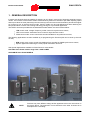
1
INSTALLATION GUIDE
SINUS PENTA
6.14.7.6.
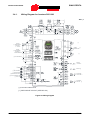
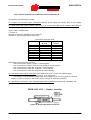
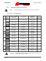
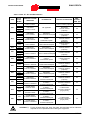
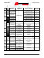
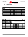
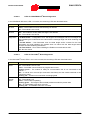
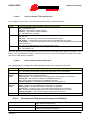
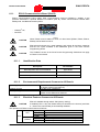
Connecting Isolated Digital Inputs
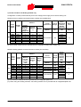
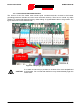
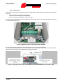
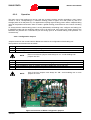
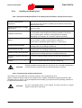
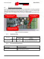
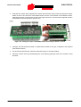
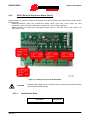
All digital inputs are galvanically isolated from zero volt of the inverter control board. To activate isolated
digital inputs, use either isolated supply delivered to terminals 44 and 49 or 24Vdc auxiliary supply.
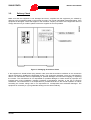
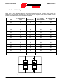
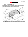
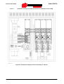
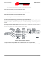
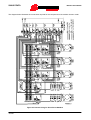
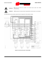
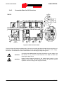
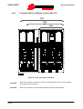
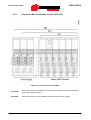
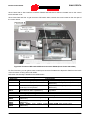
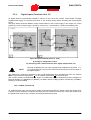
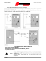
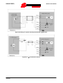
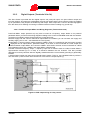
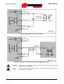
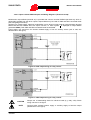
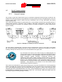
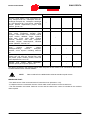
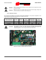
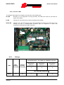
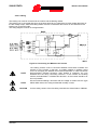
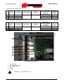
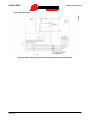
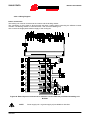
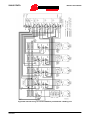
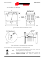
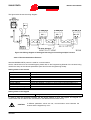
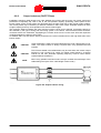
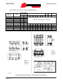
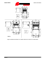
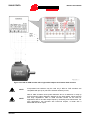
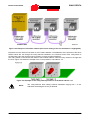
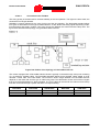
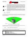
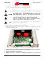
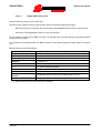
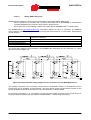
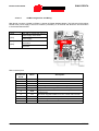
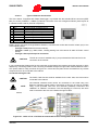
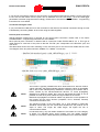
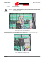
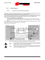
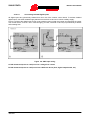
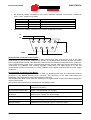
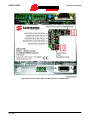
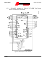
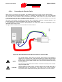
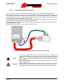
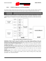
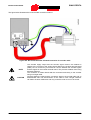
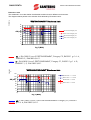
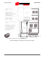
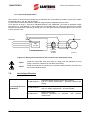
Figure 172 shows the digital input control mode exploiting power inside the inverter and exploiting the output
of a control device, such as a PLC. Internal supply (+24 Vdc, terminals 44 and 49) is protected by a 200mA
self-resetting fuse.
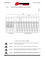
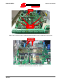
Figure 172: PNP input wiring
A: PNP Command (active to +24V) sent via a voltage free contact
B: PNP Command (active to +24V) sent from a different device (PLC, digital output board, etc.)
354/418