1
TMR900U Series
Touch Memory Reader
With USB HID Keyboard Interface
User's Manual
Manual Part Number: TM970113 REV: A
March 2010
GIGA-TMS
REGISTERED TO ISO 9001:2000
8F, No.31, Lane 169, Kang-Ning St., Hsi-Chih Taipei Hsien, 221 Taiwan
TEL:(886) 2-2695-4214
FAX:(886) 2-2695-4213
www.gigatms.com.tw
Content
Information ……………..………………………………….. 3
Introduction ……………………………………………...... 4
Specification ……………………………………………..... 5
Accessory ……………………………………………..…… 6
Technical & Operational Description ………….…..…….. 7
Pin Assignment & Connection ………………..…….……. 8
Software Operation …………………………………......… 9
Default Settings & Data Format ….………...…......…......12
Installation ……………..………………………………...…..13
2
Information
1. TMR900U series models:
● TMR900U Touch Memory Button With USB HID Keyboard Interface Reader
● TMR900UD Touch Memory Button With USB HID Keyboard Interface Reader
2. Standard package includes:
● One TMR900U Touch Memory Button With USB HID Keyboard Interface Reader
● One demo software & user manual disk.
● One accessories package.
3. Optional accessories (ordered separately)
● iButton tag
4. FCC Compliance:
This device complies with Part 15 of FCC Rules. Operation is subject to the following two
conditions: (1) This device may not cause harmful interfaces, and (2) this device must
accept any interference received, including interference that may cause undesired
operation.
5. Trademarks:
The following are the trademarks of Dallas Semiconductor Corporation:
Dallas
Dallas Semiconductor
Touch Memory Button
Touch Memory
3
Introduction
TMR900U is a device, that lets you read the Identification Code (sometimes
referred to as an ID-code or Registration number) of Dallas Semiconductor's Touch
Memory Buttons. The device is extremely simple to use: all you need to do is press the
Touch Memory Button against the touch probe, located on top of the TMR900U's housing.
ID-code will then be read out, verified against possible read errors and output into your PC
via USB interface.
TMR900U reads out and outputs touch-button's ID-code. After the read, you can
compare the data send to your PC with the data engraved on the touch button's housing.
Fig.1 shows the Touch Memory Button with the ID-code engraved on it. After the read,
computer will receive a full 16-digit string, shown below the button.
DALLAS
6A
01
00000187 AD89
DS1990A-F5
Checksum
Serial number
Family code
6A00000187 AD8901
Unique registration number
Fig1. Touch Memory Button from Dallas Semiconductor and it'sunique
16-character registration number.
Each of the 16 characters can be a digit from 0 to 9 or a capital letter from A to F.
The ID-code of any Touch Memory Buttons is absolutely unique. Dallas Semiconductor
guarantees that no two Touch Memory Buttons will ever be manufactured with the same
ID-code. Thus, the Buttons can be used for various automated password entry and in
other areas requiring a unique code.
In fact, the 16-character ID-code consists of 3 fields:
Family code
Dallas Semiconductor manufactures more than dozen different Touch
Memory models. Each model has a unique family code.
Serial number
This serial number is unique for each and any member of the device
family.
CRC
2 control characters, used to verify the correctness of the data.
-----------------------------------------------------------------------------------------------------------------------All together
Unique 16-characters serial number
All Dallas Semiconductor's Touch Memories, regardless of their type and function
have this unique registration number and utilize one single standard protocol for
registration number readout. Therefore, you can use the TMR900U to read the registration
number of any existing Touch Button.
The TMR900U also allows the user to customize the ID-code output format by
programming a Prefix and Postfix strings as well as several other options. For more details
refer to the "Programming" section of this Manual.
4
Specification
Reading capabilities
Read the ID code of all Touch Buttons conforming to Dallas
Semiconductor 1-wire protocol. (*)
PC interface
USB HID Keyboard interface
Power supply
5V through USB port
Power consumption
50mA max
Certificate
CE、FCC
Dimension
120(L) x 80(W) x 37.5(H) mm
Weight
160g
Operating Temp
-0 to 50 Deg C
Storage Temp
-10 to 60 Deg C
Humidity
10 ~ 90%
* as described in Dallas semiconductor's "Book of Touch Memory Standards”.
5
Accessory
Main Unit
( TMR900U )
Software and manual
( DISK5413 )
Accessories package
iButton Tag
( Option )
6
Technical & Operational Description
Touch Port
Status LED
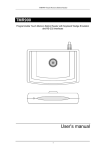
TMR900U Touch Memory Reader
Located on the upper cover is the touch port. To read the Touch Memory Button,
just press it firmly against the touch port.
There is also a 3-color (red, green and orange) status LED. When TMR900U is
powered up but no Touch Memory Button is being read, the green light is on. When normal
Touch Memory Button read is in progress, the orange light is on.
Status
Status
Green LED
Red LED
Orange LED
Buzzer
Read iButton
Tag
Power ON
OFF
OFF
ON
ON*
X
Ready
ON
OFF
OFF
OFF
O
Touch the Tag to
the touch port
OFF
OFF
ON
ON*
O*
Remove the Tag
from the touch
port
ON
OFF
OFF
OFF*
X*
Firmware
Management
Mode
OFF
ON
OFF
OFF
X
* means this function can control for iButton configure software.
7
USB Cable Pin Assignment & Connection
USB PIN Assignment
PIN1
PIN2
PIN3
PIN4
Discription
VDD
DD+
GND
Connect to PC
USB
PORT
Personal Computer
Plug the USB cable of TMR900 to any USB port of your PC. Then go to [Control
Panel]\ [System]\ [Hardware]\ [Device Manager]\ [Human Interface Devices], and see if
“HID-compliant device” appears. If “HID-compliant device” appears, it indicates TMR900U
has been detected by your computer.
8
Software Operation
Connect TMR900U with PC through USB port , then run the demo software “iButton
configure”.(You can find the software in Disk5413)
Step 1: Main page
Step 2: HID Scan
Select “ HID Port “ and click ”SCAN” to communicate TMR900U with PC. The
software will detect TMR900U and related setting. If the communication is successful, it
will show”Found TMR900U” and product information as below :
Select HID port
9
Step 3: General Settings
Click 'General' to set “Buzzer (On or Off)”, “Language (Keyboard type)” .
If necessary. Then click “Write” to save the settings to TMR900U.
Step 4: iButton Settings
Select “iButton” to set different iButton formats for data output after reading.
a. Choose the iButton data output format.
b. Choose the Pressent / Release ID format for output data.
c. Enable /Disable iButton data output of Pressent / Release .
d. Enable / Disable iButton sound of Pressent / Release.
e. Set the ID start / length of data information.
The click “Write” to save the settings to TMR900U.
10
Step 5: Package
Click “Package” to set Package, check mode, Prefix code, Postfix code, iButton
present/release message Delimiter if necessary. Then click “Write” to save the settings
to TMR900U.
Save : Click “Save” to save all settings as *.cfg file.
Open : If you want to download the settings form the file, click “Open” to open the file
and click “Write” to download the settings.
Read : If you want to know the setting of TMR900U, click ”Read” and download the file
to show it on display area.
Default : Click “Default” to reset TMR900U and get default setting if necessary.
Default values are as below (red –lined area).
Test Mode : Click “Test Mode” to into the test function window.
Cache Mode : Cache TMR900U settings for iButton configure software.
Exit : Click “Exit” to close iButton configure software.
11
Default Settings
Buzzer
Language
Present ID format
Release ID format
Present iButton
Release iButton
Present iButton Sound
Release iButton Sound
ID Start
ID Length
Prefix
Postfix
OnRemove
Package Delimiter
Check Mode
Package prefix
Package Suffix
iButton Present Prefix
iButton Present Suffix
iButton Release Prefix
iButton Release Suffix
On
USA
Family + ID + CRC
None
Enable
Disable
Enable
Disable
1
16
Empty
Empty
Empty
Data+CR+LF
Check without FS&FE
Empty
Empty
Empty
Empty
Empty
Empty
Data Format
Package Prefix
Pack FS
iButton Present / Release Sentinel
iButton Prefix
iButton SS
iButton Data
iButton ES
iButton Suffix
Pack FE
Pack Check
Pack FE 0
Pack FE 1
Package Suffix
12
Installation
13