1
TMR900 Touch Memory Button Reader
TMR900
Programmable Touch Memory Button Reader with Keyboard Wedge Emulation
and RS-232 interfaces
User’s manual
1
TMR900 Touch Memory Button Reader
Contents
1. Information
2. Introduction
3. Device controls
4. Installation
5. Programming
6. Operation
7. Specifications
3
4
6
7
11
16
17
2
TMR900 Touch Memory Button Reader
1. Information
1.1. TMR900 series models:
• TMR900
Touch Memory Button Reader
1.2. Standard package includes:
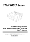
• One TMR900 Touch Memory Button Reader (comes with Master cableŒ, see
Fig.1)
• One User’s manual
1.3. Optional accessories (ordered separately):
• WAS-1289
• WAS-1288
• 1990AH
•
•
Keyboard Wedge Emulation (K.B.W.) interface cable•
RS232 interface cableŽ
Touch Button model 1990A with plastic holder
Mounting brackets
12V power adapter (for 110V or 220V)
Fig.1. Cables: Œ- Master, •- RS232, Ž- K.B.W.
1.4. FCC compliance:
This device complies with Part 15 of the FCC Rules. Operation is subject to the
following two conditions: (1) This device may not cause harmful interference, and (2)
this device must accept any interference received, including interference that may
cause undesired operation.
1.5. Trademarks:
The following are the trademarks of Dallas Semiconductor Corporation:
Dallas TM
Dallas Semiconductor TM
Touch Memory Button TM
Touch Memory TM
Windows-95 TM is a trademark of Microsoft Corp.
3
TMR900 Touch Memory Button Reader
2. Introduction
TMR900 is a device, that lets you read the Identification Code (sometimes
referred to as an ID-code or Registration number) of Dallas Semiconductor’s Touch
Memory Buttons. The device is extremely simple to use: all you need to do is press
the Touch Memory Button against the touch probe, located on top of the TMR900’s
housing. ID-code will then be read out, verified against possible read errors and output
into your PC via one of 2 available interfaces:
•Keyboard Emulation interface. This interface is called so, because it actually
emulates the regular PC keyboard. The TMR900 attaches to your computer’s
keyboard connector, while your computer’s standard keyboard is plugged into an
extra connector, provided by the TMR900. Whenever you read out the Touch Button’s
ID-code, it will be sent to your PC as a sequence of key-codes in exactly the same
fashion as when you key in the same code manually. Thus, the PC will not be able to
discriminate between actual manual input and the data sent by TMR900. This kind of
interface is very convenient as it lets you use the TMR900 with any software without
the need to modify or alter this software in order to accept the data from the TMR900.
•RS232 interface. With this interface, the TMR900 attaches to your PC’s
standard COM port and works as any regular serial input device.
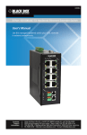
Regardless of the interface type, the TMR900 reads out and outputs touchbutton’s ID-code. After the read, you can compare the data sent to your PC with the
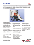
data engraved on the touch button’s housing. Fig.2. shows the Touch Memory Button
with the ID-code engraved on it. After the read, computer will receive a full 16-digit
string, shown below the button.
9702
6A
REGISTERED
E3
01
DS1 990 A-F 5
Checksum
Serial number
Family code
6A00000187AD8901
Unique registration number
Fig.2. Touch Memory Button from Dallas Semiconductor and it’s unique 16-character
registration number
Each of the 16 characters can be a digit from 0 to 9 or a capital letter from A to
F. The ID-code of any Touch Memory Button is absolutely unique. Dallas
Semiconductor guarantees that no two Touch Memory Buttons will ever be
manufactured with the same ID-code. Thus, the Button can be used for various
identification purposes (to identify objects, people, etc…), also as a key for automated
password entry and in other areas requiring a unique code.
In fact, the 16-character ID-code consists of 3 fields:
4
TMR900 Touch Memory Button Reader
Family code
Serial number
CRC
All together
Dallas Semiconductor manufactures more than dozen different
Touch Memory models. Each model has a unique family code.
This serial number is unique for each and any member of the device
family
2 control characters, used to verify the correctness of the data.
Unique 16-characthers serial number
All Dallas Semiconductor’s Touch Memories, regardless of their type and
function have this unique registration number and utilize one single standard protocol
for registration number readout. Therefore, you can use the TMR900 to read the
registration number of any existing Touch Button.
The TMR900 also allows the user to customize the ID-code output format by
programming a Prefix and Postfix strings as well as several other options. For more
details refer to the "Programming" section of this Manual.
5
TMR900 Touch Memory Button Reader
3. Device controls
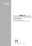
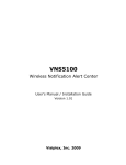
Fig.3. shows the TMR900 Touch Memory Reader.
Status LED
Touch port
Fig.3. TMR900 Touch Memory Reader
Located on the upper cover is the touch port. To read the Touch Button, just
press it firmly against the touch port.
There is also a 3-color (red, green and orange) status LED. When TMR900 is
powered up but no touch memory is being read, the green light is on. When normal
Touch Memory read is in progress, the orange light is on. When the Touch Memory
read is not successful, the red light is on.
6
TMR900 Touch Memory Button Reader
4. Installation
The Installation process depends on what kind of interface cable you are using.
Please refer to whatever section is applicable to you.
4.1. Installing the TMR900 with the K.B.W. Interface cable.
To your PC’s
keyboard
connector
Fig.4. Attaching the TMR900 to the PC via K.B.W. interface cable
To connect the TMR900 to the PC via K.B.W. interface:
• Turn off your PC.
• Unplug the keyboard.
• Examine the K.B.W. interface cableŽ to find 3 different connectors. One of them
looks exactly like your keyboard’s connector. Plug this connector into your PC.
• Plug your keyboard into another round connector found on the K.B.W. interface
cableŽ.
• Finally, plug the K.B.W. interface cable into the 15-pin connector found on the
Master cableΠcoming out of the TMR900.
• Turn your computer on. On power-up, the TMR900 should produce the long
‘BEEP’ sound and the Status LED will turn green.
• Check the normal functioning of your keyboard by sending some keystrokes to
your PC (press some keys, toggle ‘CAPS LOCK’, etc…). The keyboard should
work normally, as TMR900 features absolute transparency for all communications
between keyboard and PC.
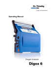
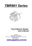
• Now try to read the Touch Button. Press the Button firmly against the touch port as
shown on Fig.5A. The TMR900 will produce a short beep and the Status LED will
turn orange, thus indicating that the read was successful. Avoid pressing the
Touch Memory as shown on Fig.5B. In this case, the successful read may not be
possible. However, no damage to the device will happen too.
7
TMR900 Touch Memory Button Reader
A
B
Pressing the touch button
against touch port:
A-correct
B-incorrect
Fig.5. Correct (A) and incorrect (B) alignment of the touch button
After this, you should see the Touch Button’s registration number printed on
your PC’s display.
If you are in DOS, you will see something like that:
C:\>6A00000187AD8901
Bad command or file name
C:\>
Don’t be surprised at the computer’s attempt to interpret this code as some
command you want to process. PC itself cannot discriminate between regular
manual keyboard input and TMR900 input. And TMR900 also emulates the <Enter>
keystroke after each read (this is a default factory setting that can be customized. For
more information, refer to the "Programming" section of this Manual). This causes the
DOS to process the line as a regular command.
4.2. Installing the TMR900 with the RS232 interface cable.
To your PC’s
COM port
From 9-12V
wall adapter
Fig.6. Attaching TMR900 to the PC via RS232 interface.
Attention: you will need to have at least one free COM port on your PC in order
to install this device. You will also need a wall power adapter with output voltage in the
9-12V range.
8
TMR900 Touch Memory Button Reader
To connect TMR900 to the PC via RS232 interface:
• Turn off your PC.
• Locate an unused COM (serial) port on your PC.
• Plug the 25-pin connector of the RS232 interface cable • into PC's COM port
• Plug the RS232 interface cable • into the 15-pin connector found on the Master
cable Πcoming out of the TMR900.
• Plug the power adapter into the wall outlet and it’s connector- into the socket found
on the RS232 interface cable 25-pin connector.
• On power-up the TMR900 should produce the long ‘BEEP’ sound and the Status
LED will turn green.
To check the device functioning, you will need to use some terminal software.
The term “terminal” refers to the ability of the software to send, receive and display
the data that is being transmitted through the serial (COM) port of your computer.
There are dozens of suitable programs on the market.
However, one program in particular is very common and comes as a part of
Windows-95 operating system. This program is called HyperTerminal and can be
found in the 'Accessories' folder of the 'Programs' group of the 'Start' menu.
Note: The explanation below assumes that you have a basic knowledge of
Windows-95.
To test the TMR900 functioning:
• Launch the HyperTerminal.
• On start-up, the Dialog box will be displayed, requesting you to type in the name of
your connection. You can supply any name, for instance: ‘TEST’
• The next dialog box will ask for telephone number. This is because the
HyperTerminal also works with modems. In your case, the telephone number is
not applicable, so you don’t have to enter it. Just select the appropriate COM port
from the ‘Connect using’ drop-down list. For example, if your TMR900 is attached
to the COM2, you should select 'Direct to COM2'
• The next dialog will prompt for port settings. Here is what you should choose:
Bits per second
Data bits
Parity
Stop bits
Flow control
9600
8
None
1
None
• After this dialog closes, the program is finally satisfied and the terminal screen is
displayed
• Now try to read the Touch Button. Press the Button firmly against the touch port as
shown on Fig.7A. The TMR900 will produce a short beep and the Status LED will
turn orange, thus indicating that the read was successful. Avoid pressing the
Touch Memory as shown on Fig.7B. In this case, the successful read may not be
possible. However, no damage to the device will happen too.
A
B
Pressing the touch button
against touch port:
A-correct
B-incorrect
Fig.7. Correct (A) and incorrect (B) alignment of the touch button
9
TMR900 Touch Memory Button Reader
After read, you should see the touch button’s registration number printed in the
terminal window:
6A00000187AD8901
10
TMR900 Touch Memory Button Reader
5. Programming
Important: in order to be reprogrammed, the TMR900 must be connected to
the host computer via RS232 interface cable. It is not possible to program the
TMR900 through K.B.W. interface cable.
The TMR900 can function with external keyboard attached as well as without
external keyboard. "External keyboard type setting" allows the user to choose
Standard US keyboard, German Keyboard, French Keyboard or NO External
keyboard option. Note: There is no difference in device functioning between the US,
German and French settings. Those settings are reserved for the future device
versions and absolutely equal under current TMR900 version. Choosing either US,
German or French keyboard will produce the same effect: TMR900 will expect an
external keyboard to be attached. Standard desktop PC will not boot up properly if
external keyboard is selected in the Setup but no keyboard actually attached to the
TMR900 ("No Keyboard or Keyboard Error" message will be displayed). Choosing NO
external Keyboard will put TMR900 into so-called Master mode of operation. No
external keyboard is required in this mode, PC will boot up properly. External keyboard
connected to the TMR900 running in the Master mode will still function, however
some features will not work properly (for example, CAPS lock and other lamps will
always be OFF).
The TMR900 allows the user to customize the data output format. In particular,
the user may define (customize) the following optional fields, that will be output
together with the Touch Button's ID code itself.
Prefix
Postfix
Delimiter
up to 7 ch.
up to 7 ch.
From characterNumber of Characters
1 to 16
optional string that precedes the ID code
optional string that follows the ID code
special character (or 2) that is transmitted
after the Postfix and intended to separate ID
codes from one another
Those 2 setting allow the user to define the
portion of ID code that will be actually sent to
PC.
With all 3 optional fields enabled the output format will be as follows:
Prefix
ID-code
Postfix
Delimiter
*Note: all fields except ID-code (main) field are
optional. The user can disable any field by setting it's length to zero.
Ability to customize the data output format is very useful as it allows the user to
fine tune the TMR900 functioning to the requirements of the host software. By setting
the right data in the optional fields, the user can avoid manual key entry prior and/or
after the ID-code transmission.
Consider, for example, that some existing software requires to first type in the
'CD_' command, followed by the ID-code followed by the <LF>+<CR> character (to
execute command). If not for programmable fields, the user would have to manually
type in the command, then scan the touch-memory and then press <Return> key.
With optional fields, the user can program the command into the Prefix and choose
an appropriate delimiter (<LF>+<CR>) to completely avoid any manual key entry.
11
TMR900 Touch Memory Button Reader
The user may also tune the ID code output format by choosing to transmit only
some portion of the ID code. This can also be very handy when accommodating the
TMR900 for use with the existing software.
Another customizable feature of TMR900 is an optional 'OnRemove' string. This
string is not transmitted together with the code. Rather, it is sent whenever the touchmemory is removed (detached) from the touch-memory port. This feature is useful in
applications, where touch memory is used as an access key and data entry or other
manipulation is not allowed when Touch Button is not present. One good example is
an order-processing terminal in a restaurant. The waiter is normally required to scan
the ID-card (Touch Memory Button in this case) before he will be able to enter the
order. The Touch Button must be present (attached to the touch port) during the
whole period of order entry.
The OnRemove feature allows to control the presence of a Touch Button. Once
it is removed, the OnRemove string (code) will be send to the host to notify the
software. The OnRemove string format is as follows:
OnRemove
Delimiter
Note: Delimiter is the same for ID-code transmission and for 'OnRemove'
string. If 'OnRemove' is disabled, the Delimiter is also not transmitted.
All settings defined by the user are stored in the non-volatile memory. Once set,
they remain intact until the user redefines them.
To change the settings, the user must first connect the TMR900 to the PC (or
any other suitable data terminal) via RS232 interface as described in the "Installation"
section of this Manual.
No special host software is required for programming. Rather, the TMR900
uses a terminal-style programming. Any host terminal software capable of sending
and receiving data over the serial channel is good for this purpose. One widely
available program is HyperTerminal (it is included into the standard Windows-95
package). Refer to the "Installation" section of this Manual for step-by-step description
on how to use this program with the TMR900.
To program the TMR900 settings:
• Attach the TMR900 to the host computer via RS232 interface as described in the
"Installation" section.
• Run the terminal program of your choice.
• Set the communication parameters to 9600 bits per second,8 bits ,1 stop bit, no
parity bit.
• Set the 'Echo' option to 'Enabled' (in order to be able to see what you are typing).
For HyperTerminal:
• choose File/Properties from the Main menu.
• When 'Properties' dialog box opens, click on the 'Settings' tab.
• In the 'Settings' tab, click on the 'ASCII setup…' button. 'ASCII setup' dialog
will open.
• Check (enable) 'Echo typed characters locally' option.
• Close the dialog by clicking 'OK' button.
• To enter setup, type in the word 'SETUP' in uppercase (capital) letters and press
<Enter>.
• The TMR900 will execute 4 consecutive short beeps and enter the setup mode.
During setup, the Status LED will constantly blink in green color.
12
TMR900 Touch Memory Button Reader
Once setup is entered, the TMR900 will display (i.e. print on the terminal
screen) the following title:
**** TMR900 SETUP ****
Type "H" for Help.
---------------------The title will be followed by the setup prompt:
Enter Command/Setting>
The user interacts with the setup program by entering commands. The list of
available commands can be obtained by typing in the 'H' (Help) command. The
TMR900 will print out the following message:
Enter Command/Setting>h
Available Commands
H....Prints this message
P....Prints the current status of all settings
D....Loads default values for all settings
E....Exits the setup
Available Settings
1....Prefix [up to 7 characters long]
2....Postfix [up to 7 characters long]
3....delimiter [special symbol, selection]
4....OnRemove [up to 7 characters long]
....5....External Keyboard type
....6....From Character [1..16]
....7....Number of Characters [1..16]
Entering 'P' (Print) command lets the user evaluate the current status of all
settings. The TMR900 is shipped from the factory with Prefix, Postfix and OnRemove
fields disabled and delimiter set to <LF>+<CR>. The 'P' command will print out the
following:
Enter Command/Setting>p
Current Settings are:
1.Prefix...................<Disabled>
2.Postfix..................<Disabled>
3.Delimiter................<CR>+<LF>
4.OnRemove.................<Disabled>
....5.External Keyboard type...US Keyboard (Standard)
....6.From character...........1
....7.Number of characters.....16
The user can return to these default factory settings at any time by entering a
'D' (Default) command:
Enter Command/Setting>D
Default values has been loaded
13
TMR900 Touch Memory Button Reader
To alter the value of any setting, type in the appropriate setting number.
For setting 1,2 and 4, you will be prompted to enter the string of up to 7
characters long. Type the desired string and press <Return> key.
Enter Command/Setting>1
Input Prefix [Max. 7 char., <Enter> for none]:
Note: Backspace and other forms of editing are not allowed. If you make
mistake, Press <Enter> and choose to edit the same setting again. Pressing <Enter>
without typing any string disables the corresponding setting. If string of more then 7
characters is entered, it is truncated to first 7 characters.
For Setting #3, the user is prompted to make a choice from the list of available
delimiters:
Enter Command/Setting>3
Select Delimiter
1....<CR>
2....<LF>
3....<CR>+<LF>
4....<TAB>
Choose one, <Enter> for none:
Selecting one of the digits sets the corresponding delimiter, pressing <Enter>
disables delimiter function.
External Keyboard is selected in the same manner. The user is prompted with
the following message:
Enter Command/Setting>5
Select External Keyboard type
1....US Keyboard (standard)
2....German Keyboard
3....French Keyboard
4....NO External Keyboard present
Choose one, <Enter> for NO External Keyboard:
Selecting US, German or French keyboard puts the TMR900 into the Slave
mode of operation whereas external keyboard must be connected (otherwise PC will
not boot up properly). Choosing "NO External Keyboard present" or pressing
<ENTER> will put the TMR900 into the Master mode of operation. In this mode,
external keyboard need not be connected for proper PC boot-up.
The user may program the TMR900 to only transmit some portion of the ID
code, not the whole ID code. Two setting: "From character" and" Number of
characters" define which part of ID code will be transmitted to the PC upon
successful read. "From character" defines the number of the first character of ID
code that will be sent to PC (characters count starts from 1). The user can program
this setting to any value from 1 to 16:
Enter Command/Setting>6
From character (1..16),<Enter> for 1:
14
TMR900 Touch Memory Button Reader
Pressing <ENTER> without entering any number will set the value to 1, which
means that no characters will be cut from the left of the ID code.
"Number of characters" defines how may characters will be transmitted. The
user may enter any value from 1 to 16:
Enter Command/Setting>6
Number of characters (1..16),<Enter> for 16:
Pressing <ENTER> will set the value of this setting to 16 (which means that
maximum possible number of characters will be transmitted). Please, note, that in
some cases the actual number of transmitted characters will be less then the one
defined in "Number of characters" setting. For example, if "From character" is set to
5, and "Number of characters" is set to 16, only 12 characters will be transmitted, as
there is only 12 characters available starting from character #5 and to the end of ID
code. Setting the "From character" to 1 and "Number of characters" to 16 will make
the TMR900 transmit the whole ID code.
To exit the setup, type in 'E' (Exit). The TMR900 will print:
Setup exited...
and resume normal operation.
15
TMR900 Touch Memory Button Reader
6. Operation
After you have installed, tested and programmed the device, there is little to
learn about the TMR900’s operation. However, there are few things that should be
commented on.
6.1. Debounce logic.
The TMR900 features a so called debounce logic, which prevents the device
from reading the same Touch Buttons ID many times. The TMR900 reads the Touch
Button's ID code so fast, that even briefest contact between the Touch Button and
touch port can be enough for successful read. Because of natural human hand
shaking, each time you press the Button against the port, you actually produce many
good touches, which, if not for the debounce logic, could potentially send several
similar codes to your PC. To avoid this, the TMR900 requires you to completely
remove the Touch Button from the port for at least 1.5 seconds before this very
Touch Button can be read again.
This rule has no effect on consecutive reading of different Touch Buttons. You
can read them without any delay, because they all carry different ID codes.
6.2. Status LED.
When you press the Touch Button against the port, the data is only sent to your
PC once (because of the debounce logic, see the section above). However, the
status LED remains orange until you remove the Button. This is because the
successful reads are actually go on and on, only the data is not sent to the PC.
If the Status LED turns red, this indicates the unsuccessful read. There are 2
possible causes for the read error. The first one is a faulty Touch Button itself.
However, this is highly improbable. The second cause is the incorrect touch you are
making. There is a possibility to misalign the Button is such a way, that it’s bottom
cover will short-circuit both outer and inner contacts of the touch port. In this case, the
good touch is impossible and the Status LED will be red until you remove the Button
or align it properly.
16
TMR900 Touch Memory Button Reader
7. Specifications:
Reading capabilities:
Reads the ID code of all Touch Buttons
conforming to Dallas Semiconductor 1wire protocol*
RS232 and K.B.W. (Keyboard Wedge
Emulation)
5V through K.B.W. interface cable or
9-12V through RS232 cable
50mA max.
Temperature range: 0-45 Degrees C.,
Humidity: 10-90%
PC interfaces:
Power supply:
Power consumption:
Operation conditions:
*As described in Dallas semiconductor's "Book of Touch Memory Standards".
17