1
The following document contains information on Cypress products.
FUJITSU SEMICONDUCTOR
CONTROLLER MANUAL
MN706-00008-1v0-E
FM3 Family
μT-Kernel Specification Compliant
μT-REALOS/M3 for RVDS
USER'S GUIDE
FM3 Family
μT-Kernel Specification Compliant
μT-REALOS/M3 for RVDS
USER'S GUIDE
FUJITSU SEMICONDUCTOR LIMITED
Preface
■ Purpose and Intended Reader of This Manual
This manual is intended to be read by those who create application programs using μTREALOS/M3 for RVDS (referred to as "μT-REALOS" hereafter), and describes the overall
functionality of μT-REALOS, how to create application programs, and the procedure for
building a system.
μT-REALOS is a μT-Kernel specification real-time OS that runs on the Fujitsu microcontroller
FM3 Family (referred to as "FM3" hereafter). FM3 adopts ARM Cortex-M3 core.
Reading this manual requires basic knowledge of the Cortex-M3 architecture and μT-Kernel,
which is available from the following documents.
• "Cortex-M3 Technical Reference Manual" (the architecture of FM3)
• "μT-Kernel Specification" (the specification of μT-Kernel)
See the following document for details on the system call interfaces.
• "μT-REALOS/M3 API Reference" (referred to as "API Reference" hereafter)
■ About the μT-Kernel
The μT-Kernel specifications are specifications for an open real-time OS established by the TEngine Forum. The μT-Kernel specifications are available from the T-Engine Forum website
(http://www.t-engine.org/). The original copyright for the μT-Kernel belongs to Mr. Ken
Sakamura. The copyright for the μT-Kernel specifications belongs to the T-Engine Forum. This
product uses the μT-Kernel source code from the T-Engine Forum (www.t-engine.org) based on
the μT-License.
i
■ Trademarks
Microsoft, Windows and Windows Media are either registered trademarks of Microsoft
Corporation in the United States and/or other countries.
ARM is a registered trademark of ARM Limited. Cortex is a trademark of ARM Limited. All
other brands or product names are the property of their respective holders. "ARM" is used to
represent ARM Holdings plc; its operating company ARM Limited; and the regional
subsidiaries: ARM Inc.; ARM KK; ARM Korea Limited.; ARM Taiwan Limited; ARM France
SAS; ARM Consulting (Shanghai) Co. Ltd.; ARM Belgium N.V.; ARM Germany GmbH;
ARM Embedded Technologies Pvt. Ltd.; ARM Norway, AS and ARM Sweden AB.
REALOS is a trademark of Fujitsu Semiconductor Limited.
TRON is an abbreviation of "The Real-time Operating system Nucleus".
ITRON is an abbreviation of "Industrial TRON".
μITRON is an abbreviation of "Micro Industrial TRON".
T-Kernel and μT-Kernel are the name of computer specifications, and do not refer to a
particular product or group of products.
The company names and brand names herein are the trademarks or registered trademarks of
their respective owners.
■ Overall Structure of This Manual
This manual consists of five chapters and an appendix as follows.
CHAPTER 1 OVERVIEW OF μT-REALOS
This chapter explains an overview of μT-REALOS. μT-REALOS is a μT-Kernel
specification real-time OS that runs on the FM3 family. μT-REALOS is conforms to the
μT-Kernel specifications.
CHAPTER 2 BASIC CONCEPTS OF THE μT-REALOS KERNEL
This chapter explains the basic concepts that are required to understand the μT-REALOS
kernel.
CHAPTER 3 μT-REALOS FUNCTIONS
This chapter explains the functions supported by μT-REALOS.
CHAPTER 4 WRITING A USER PROGRAM
This chapter describes the basic items in writing a user program on μT-REALOS.
CHAPTER 5 HOW TO CONSTRUCT A SYSTEM
This chapter explains how to construct a user system.
APPENDIX
The appendix explains error messages of the configurator.
■ Reference Manuals
See the manuals listed below as required while using this system.
• "Cortex-M3 Technical Reference Manual"
• "μT-Kernel Specification"
• "μT-REALOS/M3 API Reference"
ii
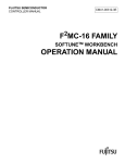
■ Organization of the μT-REALOS Manuals
The μT-REALOS manuals are divided into the following three volumes.
First-time users of μT-REALOS should read the "μT-REALOS/M3 User's Guide" first.
T-Kernel Specification
Compliant
T-REALOS/M3 for RVDS
User’s Guide
Explains the overall functionality of T-REALOS,
how to create application programs, and the procedure
for building a system. (This document)
T-Kernel Specification
Compliant
T-REALOS/M3
API Reference
Explains the details of the T-REALOS API.
iii
■ How to read This Manual
● Explanation of terminology
The terminology used in this manual is described below.
Word
Overview
Kernel
The program that provides the OS functionality is called the kernel.
User program
Refers to application programs that use μT-REALOS functions. In order to emphasize
the point that these programs are created by the user, these are called user programs in
this manual.
User system
Refers to an executable program formed by linking a user program with μT-REALOS.
System call
The group of functions that implement OS functionality and that can be called directly
from a user program are called system calls.
Object
The resources that are handled by the kernel are called objects. Specifically, this refers
to semaphores, mailboxes, and other objects that implement functionality such as tasks,
synchronization, and communications.
Configuration
definition macros
The configuration definition macros are written in the system configuration file, and
act as an interface for setting kernel configuration parameters.
Idle state
The state when there are no tasks ready to execute.
iv
•
•
•
•
•
•
•
The contents of this document are subject to change without notice.
Customers are advised to consult with sales representatives before ordering.
The information, such as descriptions of function and application circuit examples, in this document are presented
solely for the purpose of reference to show examples of operations and uses of FUJITSU SEMICONDUCTOR
device; FUJITSU SEMICONDUCTOR does not warrant proper operation of the device with respect to use based
on such information. When you develop equipment incorporating the device based on such information, you must
assume any responsibility arising out of such use of the information. FUJITSU SEMICONDUCTOR assumes no
liability for any damages whatsoever arising out of the use of the information.
Any information in this document, including descriptions of function and schematic diagrams, shall not be
construed as license of the use or exercise of any intellectual property right, such as patent right or copyright, or any
other right of FUJITSU SEMICONDUCTOR or any third party or does FUJITSU SEMICONDUCTOR warrant
non-infringement of any third-party's intellectual property right or other right by using such information. FUJITSU
SEMICONDUCTOR assumes no liability for any infringement of the intellectual property rights or other rights of
third parties which would result from the use of information contained herein.
The products described in this document are designed, developed and manufactured as contemplated for general
use, including without limitation, ordinary industrial use, general office use, personal use, and household use, but
are not designed, developed and manufactured as contemplated (1) for use accompanying fatal risks or dangers that,
unless extremely high safety is secured, could have a serious effect to the public, and could lead directly to death,
personal injury, severe physical damage or other loss (i.e., nuclear reaction control in nuclear facility, aircraft flight
control, air traffic control, mass transport control, medical life support system, missile launch control in weapon
system), or (2) for use requiring extremely high reliability (i.e., submersible repeater and artificial satellite).
Please note that FUJITSU SEMICONDUCTOR will not be liable against you and/or any third party for any claims
or damages arising in connection with above-mentioned uses of the products.
Any semiconductor devices have an inherent chance of failure. You must protect against injury, damage or loss
from such failures by incorporating safety design measures into your facility and equipment such as redundancy,
fire protection, and prevention of over-current levels and other abnormal operating conditions.
Exportation/release of any products described in this document may require necessary procedures in accordance
with the regulations of the Foreign Exchange and Foreign Trade Control Law of Japan and/or US export control
laws.
The company names and brand names herein are the trademarks or registered trademarks of their respective
owners.
Copyright© 2008-2011 FUJITSU SEMICONDUCTOR LIMITED. All rights reserved.
Copyright© 2006-2008 T-Engine Forum. All rights reserved.
This manual is made based on the specification of μ-Kernel with the formal agreement by the T-Engine Forum.
v
vi
CONTENTS
CHAPTER 1
1.1
1.2
1.3
CHAPTER 2
2.1
2.2
2.2.1
2.2.2
2.2.3
2.2.4
2.2.5
2.2.6
2.2.7
2.3
2.4
2.5
2.6
BASIC CONCEPTS OF THE μT-REALOS KERNEL ...................... 5
System Calls ........................................................................................................................ 6
Execution Units of User Program ........................................................................................ 7
Tasks .............................................................................................................................. 8
Initialization Routines .................................................................................................... 12
Interrupt Handlers ......................................................................................................... 13
Time Event Handlers .................................................................................................... 14
Error Routines .............................................................................................................. 16
Extended SVC Handlers ............................................................................................... 17
Device Processing Functions ....................................................................................... 18
Objects .............................................................................................................................. 19
System States ................................................................................................................... 20
Dispatch and Interrupts Enabled/disabled States .............................................................. 22
Precedence of Execution of Tasks and Handlers .............................................................. 23
CHAPTER 3
3.1
3.2
3.3
3.4
3.4.1
3.4.2
3.4.3
3.5
3.5.1
3.5.2
3.5.3
3.6
3.6.1
3.6.2
3.7
3.7.1
3.7.2
3.7.3
3.8
3.9
3.10
3.11
3.12
3.13
OVERVIEW OF μT-REALOS ........................................................... 1
Supported Functions ........................................................................................................... 2
Structure of Product ............................................................................................................. 3
Tools Required for Development ......................................................................................... 4
μT-REALOS FUNCTIONS ............................................................. 27
Overview of μT-REALOS Functions ..................................................................................
Task Management Functions ............................................................................................
Task Synchronization Functions ........................................................................................
Synchronization and Communication Functions ...............................................................
Semaphore Functions ..................................................................................................
Event Flag Functions ....................................................................................................
Mailbox Functions .........................................................................................................
Extended Synchronization and Communication Functions ...............................................
Mutex Functions ...........................................................................................................
Message Buffer Functions ............................................................................................
Rendezvous Port Functions .........................................................................................
Memory Pool Management Functions ...............................................................................
Fixed-size Memory Pool Functions ..............................................................................
Variable-size Memory Pool Functions ..........................................................................
Time Management Functions ............................................................................................
System Time Management Functions ..........................................................................
Cyclic Handler Functions ..............................................................................................
Alarm Handler Functions ..............................................................................................
Interrupt Management Functions .......................................................................................
System State Management Functions ...............................................................................
Subsystem Management Functions ..................................................................................
Device Management Functions .........................................................................................
Power Saving Functions ....................................................................................................
Kernel Configuration Function ...........................................................................................
vii
28
29
30
31
32
34
35
37
38
42
44
47
48
49
50
51
52
54
55
56
57
58
60
61
CHAPTER 4
4.1
4.2
4.3
4.4
4.5
4.6
4.7
4.8
4.9
4.10
4.11
4.12
4.13
Configuring a User Program ..............................................................................................
Activation Flow ..................................................................................................................
Reset Entry Routine ..........................................................................................................
Initial Routine .....................................................................................................................
Task ...................................................................................................................................
Cyclic Handler ...................................................................................................................
Alarm Handler ....................................................................................................................
Interrupt Handler ................................................................................................................
Error Routine .....................................................................................................................
Power Saving Routine .......................................................................................................
Extension SVC Handler .....................................................................................................
Device Driver .....................................................................................................................
Notes when Writing a User Program .................................................................................
CHAPTER 5
5.1
5.2
5.3
5.4
WRITING A USER PROGRAM ...................................................... 69
70
71
72
75
77
81
82
83
85
86
87
88
91
HOW TO CONSTRUCT A SYSTEM .............................................. 93
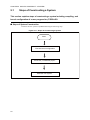
Steps of Constructing a System ........................................................................................ 94
Kernel Configuration .......................................................................................................... 95
Create the μT-REALOS Project ......................................................................................... 97
Build a User System ........................................................................................................ 100
APPENDIX ............................................................................................................. 101
APPENDIX A Error Messages of the Configurator ...................................................................... 102
INDEX ......................................................................................................................113
viii
CHAPTER 1
OVERVIEW OF μT-REALOS
This chapter explains an overview of μT-REALOS.
μT-REALOS is a μT-Kernel specification realtime OS that runs on the FM3 family.
μT-REALOS is conforms to the μT-Kernel
specifications.
1.1 Supported Functions
1.2 Structure of Product
1.3 Tools Required for Development
1
CHAPTER 1 OVERVIEW OF μT-REALOS
1.1
Supported Functions
This section explains the supported functions of μT-REALOS.
■ Supported Functions
μT-REALOS supports the functions listed below.
For details on the functions, see "CHAPTER 3 μT-REALOS FUNCTIONS" herein and
"CHAPTER 3 SYSTEM CALL INTERFACE" in "API Reference".
• Task management functions
• Task synchronization functions
• Synchronization and communication functions (semaphores, event flags, mailboxes)
• Extended synchronization and communication functions (mutexes, message buffers,
rendezvous ports)
• Memory pool management functions (fixed length memory pool, variable length memory
pool)
• Time management functions
• Interrupt management functions
• System configuration management functions
• Subsystem management functions
• Device management functions
• Power saving functions
The following development tools are also provided with μT-REALOS for use when building or
debugging a system. These are Windows applications that run on a PC.
• μT-REALOS Configurator
μT-REALOS Configurator (referred to as the "Configurator" in this manual) is used when
building a user system to configure the kernel based an a predefined structure. See "3.13
Kernel Configuration Function" for details on the Configurator functions.
2
CHAPTER 1 OVERVIEW OF μT-REALOS
1.2
Structure of Product
This section explains the structure of the product.
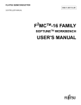
■ Structure of Product
The structure of μT-REALOS is shown below.
Figure 1.2-1 Structure of μT-REALOS
Development
tools
Kernel
Kernel
libraries
Kernel
header files
Configurator
Samples
Sample
programs
Sample
build-related
files
• Configurator
The Configurator modules that run under Windows. They are command format (.exe)
executable files that are run from the command prompt window.
• Kernel libraries
The μT-REALOS kernel object files are included in the library format.
• Kernel header files
Header files that are included by user programs, and which define system calls and
parameter types.
• Sample programs
Samples programs of reset entry routines, initialization processing, timer interrupt handlers,
and tasks.
• Sample build-related files
These are project files, configuration files, and other files for the sample programs.
3
CHAPTER 1 OVERVIEW OF μT-REALOS
1.3
Tools Required for Development
This section explains the tools that are required to develop a user system.
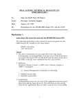
■ Tools Required for Development
The following tools are required to develop a μT-REALOS user system.
• Cross-development tool
ARM's RealView Development Suite (RVDS)
• Emulator
ARM's RealView ICE (RVI)
For details on the tool version, see Release Notes.
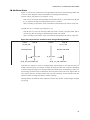
Figure 1.3-1 Structure of Development Tools
PC
Cross-development
tool
Language tool
Debugger
4
Emulator
Board for
debugging
CHAPTER 2
BASIC CONCEPTS OF
THE μT-REALOS KERNEL
This chapter explains the basic concepts that
are required to understand the μT-REALOS
kernel.
2.1 System Calls
2.2 Execution Units of User Program
2.3 Objects
2.4 System States
2.5 Dispatch and Interrupts Enabled/disabled States
2.6 Precedence of Execution of Tasks and Handlers
5
CHAPTER 2 BASIC CONCEPTS OF THE μT-REALOS KERNEL
2.1
System Calls
This section explains the system calls which act as interfaces for using kernel
functions from the user program.
■ System Calls
The interfaces for calling kernel functions from a user program are called system calls. The
system calls conform to the μT-Kernel specifications.
See "CHAPTER 3 SYSTEM CALL INTERFACE" of the "API Reference" for details on the
system calls.
6
CHAPTER 2 BASIC CONCEPTS OF THE μT-REALOS KERNEL
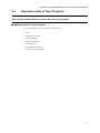
2.2
Execution Units of User Program
This section explains the execution units of a user program.
■ Execution Units of User Program
The execution units of a user program are listed below:
• Tasks
• Initialization routines
• Interrupt handlers
• Time event handlers
• Error routines
• Extended SVC handlers
• Device processing functions
7
CHAPTER 2 BASIC CONCEPTS OF THE μT-REALOS KERNEL
2.2.1
Tasks
This section explains tasks.
■ Tasks
Tasks are the program execution unit that form the basis of user program processing.
μT-REALOS saves the state prior to the interrupt (register values) on a per-task basis if the
execution of a task is interrupted. This is called the task context. The information saved in the
task context can be used to resume execution of the interrupted task.
Tasks have a variety of states, including the run state, ready state, wait state, etc. See "■Task
Portion Transitions" for details on the task portion transitions.
■ Invoking Task and Other Tasks
When a system call is made from a task, the calling task is called the invoking task and all
other tasks are called other tasks.
■ Precedence and Task Priorities
The order of execution of program execution units is called the precedence. The value that
determines the precedence of a task is called the task priority. The smaller the value of the task
priority, the higher the priority. Tasks with a higher priority (small task priority value) have
precedence when executing.
The task priority consists of a base priority, current priority, and startup priority. The term task
priority by itself refers to the current priority.
● Current priority
The current priority is used to determine the execution sequence of the task.
● Base priority
The base priority is the base priority of the task, and normally has the same value as the current
priority. When mutex functions are used, however, the current priority may be changed
temporarily in some cases and can differ from the base priority. Even in these situations,
however, the modified current priority is restored to the base priority when the mutex function
has finished being used (see "3.5.1 Mutex Functions").
● Startup priority
The startup priority is the priority specified when a task is created, and the base priority of the
task is initialized to the value of the startup priority when the task starts.
■ Dispatching and Preemption
The process of switching between running tasks is called dispatching. The process of a task
that is in the run state losing the execution right is called preemption. The functionality within
the kernel that implements dispatching is called the dispatcher.
Dispatching occurs when a task that has a higher priority than the currently executing task
enters the ready state. Preemption occurs when a dispatch occurs or an interrupt handler is
activated while a task is executing.
8
CHAPTER 2 BASIC CONCEPTS OF THE μT-REALOS KERNEL
■ Task Portions
Tasks have the following states.
● RUNNING
The state where the task is running.
However, if a non-task portion is being executed, the task executed prior to the non-task
portion is executed.
● READY
The state where the task is ready to execute, but is unable to run because a task that is higher in
the precedence is currently running.
● WAITING
The state where execution has been suspended due to calling a system call with some kind of
wait condition. This is categorized into the following states depending on the wait condition.
• Wakeup wait state (waiting due to tk_slp_tsk)
• Elapsed time wait state (waiting due to tk_dly_tsk)
• Semaphore resource acquisition wait state (waiting due to tk_wai_sem)
• Event flag wait state (waiting due to tk_wai_flg)
• Receive from mailbox wait state (waiting due to tk_rcv_mbx)
• Mutex lock wait state (waiting due to tk_loc_mtx)
• Send to message buffer wait state (waiting due to tk_snd_mbf)
• Receive from message buffer wait state (waiting due to tk_rcv_mbf)
• Fixed length memory block acquisition wait state (waiting due to tk_get_mpf)
• Variable length memory block acquisition wait state (waiting due to tk_get_mpl)
• Rendezvous call/termination wait state (waiting due to tk_cal_por)
• Rendezvous accept wait state (waiting due to tk_acp_por)
● SUSPENDED
The state where execution has been forcefully suspended by another task.
● WAITING-SUSPENDED
This state is both WAITING and SUSPENDED at the same time.
● DORMANT
The state where the task has not yet been started, or the task has ended.
● NON-EXISTENT
The state where the task has not yet been created, or the task has been deleted.
9
CHAPTER 2 BASIC CONCEPTS OF THE μT-REALOS KERNEL
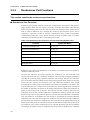
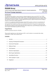
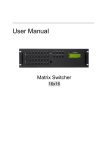
■ Task Portion Transitions
The state transitions for tasks are shown below.
Figure 2.2-1 Task Portion Transitions
Dispatch
READY
RUNNING
Preempt
Wait
condition
Release
wait
WAITING
Terminate
Suspend
Resume
WAITINGSUSPENDED
Terminate
Wait cleared
Suspend
Terminate
SUSPENDED
Resume
Start
Terminate
DORMANT
Exit
Terminate
Create
Delete
NON-EXISTENT
Exit and delete
Multiple ready state tasks are scheduled (controlling execution order) according to task
precedence. Higher precedence is given to tasks with higher task priority. For tasks with the
same task priority, higher precedence is given to the task that is transitioned into ready state
first.
10
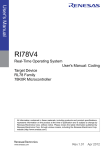
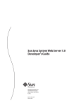
CHAPTER 2 BASIC CONCEPTS OF THE μT-REALOS KERNEL
Figure 2.2-2 Conceptual Diagram of the Precedence
The task that is highest in the precedence enters the RUNNING state
Task priority
Earlier
Higher
Order in which tasks entered the READY state
Task in
READY state
Task in
READY state
Task in
READY state
Task in
READY state
Task in
READY state
Task in
READY state
Later
Task in
READY state
Task in
READY state
Lower
The running task continues the execution until it enters the READY state after the priority
order is changed or it enters another state (WAITING state, SUSPENDED state, WAITINGSUSPENDED state, DORMANT state, NON-EXISTENT state). At that time, the task in
another READY state is not executed.
11
CHAPTER 2 BASIC CONCEPTS OF THE μT-REALOS KERNEL
2.2.2
Initialization Routines
This section explains initialization routines.
■ Initialization Routines
Initialization routines are programs using initialization processes that are unique to the user
program. In general, the user program prepares the operating environment by creating tasks
and semaphore objects, and by registrating interrupt handlers and devices.
At the startup of the kernel, one task is created (this task is called an initial task), and an
initialization routine is called from this task. An initialization routine therefore runs on a task.
12
CHAPTER 2 BASIC CONCEPTS OF THE μT-REALOS KERNEL
2.2.3
Interrupt Handlers
This section explains interrupt handlers.
■ Interrupt Handlers
An interrupt handler is a program that is activated synchronously with peripheral hardware
interrupt sources, system exceptions, and software interrupt instructions. Interrupt handlers can
be defined for each interrupt source.
If an interrupt occurs while a task is running, the kernel temporarily interrupts task execution
and runs the interrupt handler corresponding to the interrupt source that occurred. At this time,
the stack switches to the stack that is provided for executing interrupt processing (the system
stack). The interrupt handler therefore does not execute in the context of the task that had been
running, but instead executes in an independent context.
Furthermore, all of the interrupt handlers run at a higher priority than the tasks, therefore tasks
do not run until the interrupt handler has finished. If multiple interrupt handlers are activated,
task execution does not continue until all of the interrupt handlers have finished processing.
Therefore, even if an interrupt handler calls a system call that results in a dispatch (such as
starting a task with a high priority), the actual task dispatch is not performed until after all of
the interrupt handlers have finished processing. This behavior is called "delayed dispatching".
See "3.8 Interrupt Management Functions" for details on the interrupt handlers.
13
CHAPTER 2 BASIC CONCEPTS OF THE μT-REALOS KERNEL
2.2.4
Time Event Handlers
This section explains time event handlers.
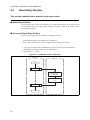
■ Time Event Handlers
Cyclic handlers and alarm handlers are collectively referred to as time event handlers.
■ Cyclic Handlers
A cyclic handler is a program that is activated at a specified interval regular. Programs that are
executed periodically can be defined as cyclic handlers, and the execution and suspension of
these handlers are able to be controlled.
If the specified interval elapses while a task is executing, the task execution is temporarily
interrupted and the corresponding cyclic handler is activated. The cyclic handler does not
execute in the context of the task that had been running, but instead executes in an independent
context.
Furthermore, all of the cyclic handlers run at a higher priority than the tasks, therefore tasks do
not run until the cyclic handler has finished. Even if the cyclic handler calls a system call that
results in a dispatch (such as starting a task with a high priority), the actual task dispatch is not
performed until after the cyclic handler has finished processing.
The cyclic handlers in μT-REALOS are activated from within isig_tim, which is called from
the timer interrupt handler for the system clock. The cyclic handlers therefore operate as part of
the timer interrupt handler. Time-related handlers that are activated from the timer interrupt
handler in this way are called "time event handlers". As described earlier, cyclic handlers
execute as part of the timer interrupt handler, and a cyclic handler is therefore not interrupted
to process other time event handlers while the cyclic handler is running.
The time when a cyclic handler is first activated is calculated based on the time tick following
the time when the cyclic handler is created or activated. However, if a cyclic handler is created
or activated from within a time event handler, the time is calculated based on the time when the
time event handler was activated. The activation time after the first time is calculated based on
the time when the cyclic handler was activated.
● Activation Phase
The relative time until the cyclic handler is first activated, based on the time of the system call
that creates the cyclic handler.
● Activation Interval
The relative time until the next cyclic handler is activated, based on the time when the cyclic
handler should have been activated (not when it was activated).
See "3.7.2 Cyclic Handler Functions" for details on cyclic handlers.
14
CHAPTER 2 BASIC CONCEPTS OF THE μT-REALOS KERNEL
■ Alarm Handlers
An alarm handler is a program that is activated at a specified time. The program that is
executed at the specified time is created as an alarm handler, and the execution and suspension
of these handlers are able to be controlled.
If the specified time is reached while a task is executing, the task execution is temporarily
interrupted and the corresponding alarm handler is executed. The alarm handler does not
execute in the context of the task that had been running, but instead executes in an independent
context.
Furthermore, all of the alarm handlers run at a higher priority than the tasks, therefore tasks do
not run until the alarm handler has finished. Even if the alarm handler calls a system call that
results in a dispatch (such as starting a task with a high priority), the actual task dispatch is not
performed until after the alarm handler has finished processing.
The alarm handlers in μT-REALOS operate as part of the interrupt handler for the system
clock. Alarm handlers are therefore not interrupted to process other time event handlers while
the alarm handler is running.
The time when the alarm handler is activated is calculated based on the time tick following the
time when the alarm handler is activated. However, if an alarm handler is activated from within
a time event handler, the time is calculated based on the time when the time event handler was
activated.
See "3.7.3 Alarm Handler Functions" for details on alarm handlers.
15
CHAPTER 2 BASIC CONCEPTS OF THE μT-REALOS KERNEL
2.2.5
Error Routines
This section explains error routines.
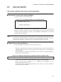
■ Error Routines
An error routine is a program that is run when the kernel detects some kind of error.
The error routine is activated under the following conditions.
• System Down
An internal kernel inconsistency is detected
• Initial Settings Error
An error occurs during kernel initialization
• Undefined Interrupt
An interrupt occurs that does not have a defined interrupt handler
The error routine is used for the purpose of debugging the user program. There is no way to
recover from the error routine. Therefore, if the error routine has been called, clear the cause of
the error and restart the system.
If an error routine is called in the initial setting error, it is executed as a task portion.
Otherwise, it is executed as a task-independent portion. For details on task portions and taskindependent portions, see "2.4 System States".
16
CHAPTER 2 BASIC CONCEPTS OF THE μT-REALOS KERNEL
2.2.6
Extended SVC Handlers
This section explains extended SVC handlers.
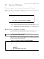
■ Extended SVC Handlers
An extended SVC handler is a handler that accepts request for subsystem. When called from a
task portion, it is executed as a quasi-task portion. When called from a task-independent
portion, it is executed as a task-independent portion. For details on subsystems, refer to "3.10
Subsystem Management Functions", and for details on quasi-task portions, refer to "2.4
System States".
17
CHAPTER 2 BASIC CONCEPTS OF THE μT-REALOS KERNEL
2.2.7
Device Processing Functions
This section explains the device processing functions.
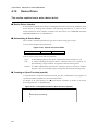
■ Device Processing Functions
A device processing function is used when a device driver function is called by a device
management function. If a device processing function is called by a task portion, it is executed
as a task portion. If it is called by a task-independent portion, it is executed as a taskindependent portion. For details on device processing functions, refer to "3.11 Device
Management Functions".
18
CHAPTER 2 BASIC CONCEPTS OF THE μT-REALOS KERNEL
2.3
Objects
This section explains objects.
■ Objects
μT-REALOS supports a variety of functions, including synchronization/communication
between tasks, exclusive control, and acquisition/release of memory regions. The resources that
operate on system calls in order to use these functions from a user program are called objects.
The following objects are supported by μT-REALOS.
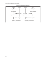
Table 2.3-1 List of Objects
Object
Synopsis
Task
The task is object in the most fundamental unit that makes up a user program.
Semaphore
Semaphores are objects for representing numerically the number and availability of
unused resources, and for managing exclusive control and synchronization when using
those resources.
Event flag
Event flags are objects that perform synchronization by representing the presence or
absence of events as bit flags.
Mailboxes
Mailboxes are objects that perform synchronization and communication by receiving
messages that are stored in memory.
Mutexes
Mutexes are objects that perform exclusive access control between tasks that use a
shared resource.
Message buffers
Message buffers are objects that perform synchronization and communication by receiving variable-length messages.
Rendezvous ports
Rendezvous ports provide intertask synchronous communication functionality, and support a single sequence where one task requests processing of another task and the second
task then returns the processing result to the first task.
The object that synchronizes the waiting of both tasks is called a rendezvous port.
Fixed-size
memory pool
Fixed-size memory pool are objects for dynamically managing fixed size memory
blocks.
Variable-size
memory pool
Variable-size memory pool are objects for dynamically managing arbitrary size memory
blocks.
Cyclic handlers
Cyclic handlers are time event handlers that activate at a fixed period.
Alarm handlers
Alarm handlers are time event handlers that activate at a specified time.
19
CHAPTER 2 BASIC CONCEPTS OF THE μT-REALOS KERNEL
2.4
System States
This section explains the system states.
■ System States
The system states of μT-REALOS are divided into the following categories.
Figure 2.4-1 System States
Task portion running
: Task program
System states
Transient states
Non-task portion running
: During OS execution
Task-independent portion running
: Interrupt handlers and time event handlers
Quasi-task portion running
: Extended SVC handlers (OS extensions),
Device driver interface function
■ Task Portion Running
"Task portion running" are the states in which task programs run. This does not include states
in which the OS (system calls) executes or states in which handlers execute, which are part of
the "Non-task portion running" described below.
■ Non-task Portion Running
"Non-task portion running" are further subdivided into the three states of "transient states",
"task-independent portion running", and "quasi-task portion running".
(1) "Transient States"
"Transient States" refer to the states in which μT-REALOS system call processing is
executed.
(2) "Task-indePendent Portion Running", "Quasi-task Portion Running"
"Task-independent Portion Running" refer to the states in which interrupt handlers and time
event handlers are executed.
"Quasi-task Portion Running" refer to the states in which extended SVC handlers and
device driver interface functions are executed.
20
CHAPTER 2 BASIC CONCEPTS OF THE μT-REALOS KERNEL
■ System Calls that can be called
Except for system calls such as tk_ret_int and isig_tim that are required to be called from a
"task-independent portion", all of the system calls can be called from the "task portions" and
"quasi-task portions".
In contrast, "task-independent portions" execute in a context that is independent of any tasks,
and do not have the concept of a task. The following system calls therefore cannot be called
from the task-independent portions.
- System calls that explicitly specify the invoking task (calls where tskid is specified using
the "TSK_SELF" macro)
- System calls that implicitly specify the invoking task (calls that enter a WAITING)
See Section "3.1 List of System Calls" of the "API Reference" for details on the system calls
that can be called from each of the system states.
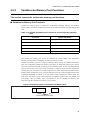
■ User Programs and System States
Table 2.4-1 shows the relationship between the parts of a user program and the system states.
Table 2.4-1 System States of Each Part of a User Program
User Program
Component
System State
Tasks
Task portion
Extended SVC handlers
Non-task portion (quasi-task portion, task-independent portion)
Device drivers
Non-task portion (quasi-task portion)
Cyclic handlers
Non-task portion (task-independent portion)
Alarm handlers
Non-task portion (task-independent portion)
Interrupt handlers
Non-task portion (task-independent portion)
Error routines
Task portion, non-task portion (task-independent portion)
Note:
The μT-Kernel specifications do not define isig_tim and error routines. These are
extended functionality that is specific to μT-REALOS.
21
CHAPTER 2 BASIC CONCEPTS OF THE μT-REALOS KERNEL
2.5
Dispatch and Interrupts Enabled/disabled States
This section explains the dispatch enabled/disabled states and the interrupts
enabled/disabled states.
■ Dispatch Enabled/disabled States
During execution of a user program, the dispatcher is either in the dispatch disabled state or the
dispatch enabled state. After system initialization, the dispatcher is in the dispatch enabled state
when the initial task begins executing.
In the dispatch disabled state, the system does not switch the task that is in the RUNNING.
While in the dispatch disabled state, an error (E_CTX) occurs if a system call is made where
there is a possibility of the currently running task entering the WAITING. However, interrupt
handlers, cyclic handlers, and alarm handlers remain active.
The dispatch disabled/enabled states can be controlled from a user program by calling the
following system calls.
- tk_dis_dsp: Enters the dispatch disabled state
- tk_ena_dsp: Enters the dispatch enabled state
■ Interrupts Enabled/disabled States
During execution of a user program, the system is either in the interrupts disabled state or the
interrupts enabled state. After system initialization, the system is in the interrupts enabled state
when the initial task begins executing.
In the interrupts disabled state, all external interrupts are disabled such that control is not
passed to an interrupt handler even if a hardware interrupt occurs.
Furthermore, if dispatching is also disabled, then the system does not switch from the currently
running task. While in the interrupts disabled state, an error (E_CTX) occurs if a system call is
made where there is a possibility of the currently running task entering the WAITING. An
error (E_CTX) also occurs if a system call is made to enable or disable dispatching (tk_dis_dsp
or tk_ena_dsp) while in the interrupts disabled state.
The interrupts enabled/disabled states can be controlled from a user program by calling the
following macros.
- DI: Enters the interrupts disabled state
- EI: Enters the interrupts enabled state
22
CHAPTER 2 BASIC CONCEPTS OF THE μT-REALOS KERNEL
2.6
Precedence of Execution of Tasks and Handlers
This section explains the precedence of execution of tasks and handlers.
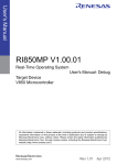
■ Precedence of Execution (Tasks vs. Interrupt Handlers and Time Event
Handlers)
Handlers have a higher precedence of execution than tasks. For example, if a hardware
interrupt occurs while a task is executing, the execution of the task is suspended and the
interrupt handler corresponding to the interrupt is executed. When the interrupt handler finishes
executing, the task resumes execution from the point where it was suspended.
Figure 2.6-1 Precedence of Execution (Tasks vs. Interrupt Handlers and Time Event Handlers)
Precedence
of execution
Interrupt
handler
Interrupt
occurs
Task
Time
23
CHAPTER 2 BASIC CONCEPTS OF THE μT-REALOS KERNEL
■ Precedence of Execution (Tasks vs. Tasks)
The precedence of execution of tasks executes tasks that have a higher priority first. If a task
with a higher priority than the task that is currently executing enters the READY, the currently
executing task is suspended and the higher priority task is executed.
Figure 2.6-2 Precedence of Execution (Tasks vs. Tasks)
Precedence
of Execution
Priority of task 2
changes from 5 to 15
Task 2
(priority = 5)
RUNNING
Task 1
(priority = 10)
READY
Task 2
(priority = 15)
RUNNING
READY
RUNNING
READY
Priority of task 2
changes from 15 to 5
Time
24
CHAPTER 2 BASIC CONCEPTS OF THE μT-REALOS KERNEL
■ Precedence of Execution (Handlers vs. Handlers)
In the precedence of execution of handlers, interrupt handlers for system exception sources
execute with the highest precedence. The precedence of execution of other interrupt handlers
depends on the hardware interrupt level (IL), with the interrupt handlers corresponding to
interrupts that have a high interrupt level (the numerical value of the interrupt level is small)
executing with precedence. Time event handlers execute as extensions of the timer interrupt
handler. The precedence of execution of time event handlers therefore depends on the interrupt
level of the timer interrupt.
Figure 2.6-3 Precedence of Execution (Handlers vs. Handlers)
Precedence
of execution
Interrupt handler
(system exception)
System
exception
occurs
Time event handler
call
Timer interrupt handler
(IL=16)
ret
Interrupt
occurs
(IL=16)
Interrupt handler
(IL=30)
Time
25
CHAPTER 2 BASIC CONCEPTS OF THE μT-REALOS KERNEL
26
CHAPTER 3
μT-REALOS FUNCTIONS
This chapter explains the functions supported
by μT-REALOS.
3.1 Overview of μT-REALOS Functions
3.2 Task Management Functions
3.3 Task Synchronization Functions
3.4 Synchronization and Communication Functions
3.5 Extended Synchronization and Communication Functions
3.6 Memory Pool Management Functions
3.7 Time Management Functions
3.8 Interrupt Management Functions
3.9 System State Management Functions
3.10 Subsystem Management Functions
3.11 Device Management Functions
3.12 Power Saving Functions
3.13 Kernel Configuration Function
27
CHAPTER 3 μT-REALOS FUNCTIONS
3.1
Overview of μT-REALOS Functions
This section explains an overview of μT-REALOS functions.
■ Overview of μT-REALOS Functions
μT-REALOS supports the following functions.
• Kernel
Task management functions
Task-dependent synchronization functions
Synchronization and communication functions (semaphores, event flags, mailboxes)
Extended synchronization and communication functions (mutexes, message buffers,
rendezvous ports)
Memory pool management functions (fixed length memory pool, variable length memory
pool)
Time management functions (system time, cyclic handlers, alarm handlers)
Interrupt management functions
System state management functions
Subsystem management functions
Device management functions
Power saving functions
• Configurator
Kernel configuration function
See "CHAPTER 3 SYSTEM CALL INTERFACE" of the "API Reference" for details on the
system calls described in this chapter.
28
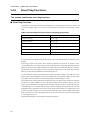
CHAPTER 3 μT-REALOS FUNCTIONS
3.2
Task Management Functions
This section explains the task management functions.
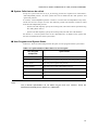
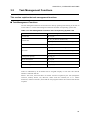
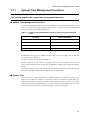
■ Task Management Functions
The task management functions are functions for directly operating and referring to the state of
a task. Table 3.2-1 shows task management functions and their corresponding system calls.
Table 3.2-1 Task Management Functions and Corresponding System Calls
Function
Create task
System Call Name
tk_cre_tsk
tk_del_tsk (Delete dormant task)
Delete task
tk_exd_tsk (Exits and deletes its invoking task)
Start task
tk_sta_tsk
tk_ext_tsk (Exits its invoking task)
Exit task
tk_exd_tsk (Exits and deletes its invoking task)
tk_ter_tsk (Forcibly terminate other task)
Change task priority
tk_chg_pri
Refer Task Status
tk_ref_tsk
Set Task Registers
tk_set_reg
Get Task Registers
tk_get_reg
Tasks are identified by an ID number that is assigned uniquely to each task. The task ID
number is called the task ID.
When a task exits, the kernel does not release resources acquired by the task (semaphore
resources, memory blocks, etc). However, mutex locks are released (see "3.5.1 Mutex
Functions"). When a task exits, ensure that the user program releases the resources that the task
acquired.
29
CHAPTER 3 μT-REALOS FUNCTIONS
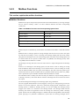
3.3
Task Synchronization Functions
This section explains the task synchronization functions.
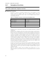
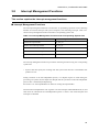
■ Task Synchronization Functions
The task synchronization functions are functions for performing synchronization by directly
operating task portions. Table 3.3-1 shows task synchronization functions and their
corresponding systems calls.
Table 3.3-1 Task Synchronization Functions and Corresponding System Calls
Function
System Call Name
Sleep task
tk_slp_tsk
Wakeup task
tk_wup_tsk
Cancel Wakeup Task
tk_can_wup
Release Wait
tk_rel_wai
Suspend Task
tk_sus_tsk
tk_rsm_tsk
Resume wait task
tk_frsm_tsk (Force Resume Task)
Delay task
tk_dly_tsk
Wakeup requests for a task are queued. That is, when an attempt is made to wake up a task that
is not in the sleep state, the attempt is remembered. After that, when the task is to go to a sleep
state, it does not enter that state. To realize this, the kernel maintains the number of wakeup
requests that have been queued for each task. This is called the "wakeup request queuing
count". When the task is started, this count is cleared to 0.
Futhermore, suspend requests for a task are nested. That is, if a task that is already in the
SUSPENDED state (including WAITING-SUSPENDED state) is placed again in the
SUSPENDED state, the attempt hereof is remembered. After that, when an attempt is made to
resume the task in SUSPENDED state (including WAITING-SUSPENDED state), it is not
resumed. To realize this, the kernel maintains the number of requests of SUSPENDED state
nested for each task. This is called the "suspend request nesting count". When the task is
started, this count is cleared to 0.
30
CHAPTER 3 μT-REALOS FUNCTIONS
3.4
Synchronization and Communication Functions
This section explains the synchronization and communication functions.
■ Synchronization and Communication Functions
The synchronization and communication functions are functions for performing
synchronization and communication between tasks using task-independent objects.
The synchronization and communication functions support the following functions.
• Semaphore functions
• Event flag functions
• Mailbox functions
31
CHAPTER 3 μT-REALOS FUNCTIONS
3.4.1
Semaphore Functions
This section explains the semaphore functions.
■ Semaphore Functions
Semaphores are objects for representing numerically data of and availability of unused
resources (called the semaphore count), and for managing exclusive control and
synchronization when using those resources. Table 3.4-1 shows semaphore functions and their
corresponding system calls.
Table 3.4-1 Semaphore Functions and Corresponding System Calls
Function
System Call Name
Create semaphore
tk_cre_sem
Delete semaphore
tk_del_sem
Signal Semaphore
tk_sig_sem
Wait on Semaphore
tk_wai_sem
Refer Semaphore Status
tk_ref_sem
Semaphore objects are identified by an ID number. The semaphore ID number is called the
semaphore ID.
Semaphores have a semaphore count and a wait queue of tasks waiting to acquire resources.
When m resources are returned (from the event notifier side), the semaphore count increases by
m. When n resources are acquired (by the event wait side), the semaphore count decreases by
n. When a task attempts to acquire semaphore resources when the number of resources is
insufficient (specifically, when the semaphore count reduces to a negative value), a task
attempting to acquire resources goes into WAITING until the next time resources are returning.
A task waiting for semaphore resources is linked to the wait queue of that semaphore.
Furthermore, a maximum resource count can be configured on each semaphore to prevent too
many resources from being returning. An error occurs when resources whose semaphore count
exceed the maximum are returned to a semaphore (specifically, when the semaphore count
increases and exceeds the maximum semaphore count).
The order of the wait queue can be selected from the two options of FIFO order (TA_TFIFO)
and task priority order (TA_TPRI). Furthermore, the precedence of resource acquisition can be
selected from the two options of task at head of wait queue first (TA_FIRST) or task with
smallest request count first (TA_CNT). These are specified as semaphore attributes when the
semaphore is created.
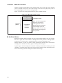
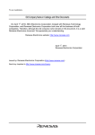
Figure 3.4-1 shows the situation when the semaphore count changes from 1 to 2 in a
semaphore with the TA_CNT attribute, where Task 1 is skipped and the resources are allocated
to Task 2.
32
CHAPTER 3 μT-REALOS FUNCTIONS
Figure 3.4-1 Example of Semaphore Wait Queue
Task 1
Task 2
Request
count=3
Request
count=2
The maximum value of the semaphore count is specified when the semaphore is created. The
upper limit on the maximum value of the semaphore count is 0x7FFFFFFF. See Section
"3.5.1.1 tk_cre_sem" in the "API Reference" for details.
33
CHAPTER 3 μT-REALOS FUNCTIONS
3.4.2
Event Flag Functions
This section explains the event flag functions.
■ Event Flag Functions
Event flags are objects that perform synchronization by representing the presence or absence of
events as bit flags. Table 3.4-2 shows event flag functions and their corresponding system
calls.
Table 3.4-2 Event Flag Functions and Corresponding System Calls
Function
System Call Name
Create event flag
tk_cre_flg
Delete event flag
tk_del_flg
Set event flag
tk_set_flg
Clear event flag
tk_clr_flg
Wait Event Flag
tk_wai_flg
Refer Event Flag Status
tk_ref_flg
Event flag objects are identified by an ID number. The event flag ID number is called the event
flag ID.
Event flags contain a bit pattern where each bit represents the presence or absence of the
corresponding event, and a wait queue of tasks waiting for those event flags. Sometimes the bit
pattern of an event flag is simply called the event flag. The event notifier side can set or clear the
specified bits of the event flag. The event wait side can bring a task to the event flag wait state
until all or some of the specified bits of the event flag are set.
A task waiting for event flag is linked to the wait queue of that event flag. The order of the wait
queue can be selected from the two options of FIFO order (TA_TFIFO) and task priority order
(TA_TPRI). This is specified as a part of flag attributes when the flag is created.
The conditions for release from the event flag wait state can specify either of the two attributes
of AND wait (TWF_ANDW) or OR wait (TWF_ORW). These attributes specify how the
release from WAITING state operates when waiting for multiple events. For the AND wait, the
WAITING state is not released until all of the events are signaled, whereas for the OR wait, the
WAITING state is released when even one of the events being waited for is signaled. It is also
possible to specify whether or not to clear the bits when the wait is released. TWF_CLR can be
used to clear all bits, while TWF_BITCLR can be used to selectively clear bits corresponding
to event flag wait criteria.
μT-REALOS manages event generation using 32-bit patterns.
34
CHAPTER 3 μT-REALOS FUNCTIONS
3.4.3
Mailbox Functions
This section explains the mailbox functions.
■ Mailbox Functions
Mailboxes are objects that perform synchronization and communication by receiving messages
that are stored in memory. Table 3.4-3 shows mailbox functions and their corresponding
system calls.
Table 3.4-3 Mailbox Functions and Corresponding System Calls
Function
System Call Name
Create mailbox
tk_cre_mbx
Delete mailbox
tk_del_mbx
Send Message to Mailbox
tk_snd_mbx
Receive Message from Mailbox
tk_rcv_mbx
Refer Mailbox Status
tk_ref_mbx
Mailbox objects are identified by an ID number. The mailbox ID number is called the mailbox
ID.
Mailboxes have a message queue for storing messages that have been sent, and a wait queue
for tasks that are waiting to receive a message. The message-sending side (the event notifier
side) places the messages to be sent in the message queue. The order of the message queue can
be selected from the two options of FIFO order (TA_MFIFO) and message priority order
(TA_MPRI) when the mailbox is created.
The message-receiving side (the event wait side) retrieves a single message from the message
queue.
If there are no messages in the message queue, the task enters a state of waiting for receipt
from the mailbox until the next message is sent. Tasks that enter a state of waiting for receipt
from the mailbox linked to the wait queue of that mailbox. The order of the wait queue can be
selected from the two options of FIFO order (TA_TFIFO) and task priority order (TA_TPRI).
This is specified as a part of mailbox attributes when the mailbox is created.
The information that is actually sent and received by the mailbox is only the starting address of
a message in memory. This means that the contents of messages that are sent and received are
not copied.
The kernel manages the messages in the message queue using a linked list.
The user program should allocate an area (msgque) at the top of a message being sent for the
kernel to use for the linked list. This area is called the message header. Furthermore, if the
message queue is ordered by message priority, an area for holding the message priority
(msgpri) also needs to be reserved in the message header. The message header and the
following area where the application stores the message are collectively called a message
packet. System calls for sending messages to a mailbox take the starting address of the message
packet (pk_msg) as a parameter. Furthermore, system calls for receiving messages from a
35
CHAPTER 3 μT-REALOS FUNCTIONS
mailbox return the starting address of the message packet as the return value. If the message
queue is arranged in the priority order of the message, an area for storing the priority order of
the message(msgpri) must exist in the message header.
Figure 3.4-2 shows the message packet format of priority-ordered messages.
Figure 3.4-2 Message Packet Format
msgque
msgpri
Message header
Note: The size of msgque and
msgpri are 4 bytes each.
Message
packet
The msgpri area must be
Transmitted/
received
message
provided when the messages
in the message queue are
priority-ordered. An error may
be returned if the msgpri area
is not provided.
■ Additional Notes
Because the mailbox functions allocate the area for the message header by the user program,
there is no upper limit on the number of messages that can be placed in a message queue.
Furthermore, the system calls for sending messages do not enter the WAITING state.
Message packets are able use memory blocks dynamically allocated from the fixed-size
memory pool or variable-size memory pool, or statically allocated regions.
Typical usage is for the sending task to allocate a memory block from the memory pool and
send this as a message packet, and for the receiving task to directly release the memory block
back to the memory pool after reading the contents of the message.
36
CHAPTER 3 μT-REALOS FUNCTIONS
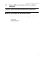
3.5
Extended Synchronization and Communication
Functions
This section explains the extended synchronization and communication
functions.
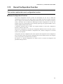
■ Extended Synchronization and Communication Functions
The extended synchronization and communication functions are functions for performing highlevel synchronization and communication between tasks using task-independent objects.
The extended synchronization and communication functions support the following functions.
• Mutex functions
• Message buffer functions
• Rendezvous port functions
37
CHAPTER 3 μT-REALOS FUNCTIONS
3.5.1
Mutex Functions
This section explains the mutex functions.
■ Mutex Functions
Mutexes are objects that perform exclusive control between tasks that use a shared resource.
Table 3.5-1 shows mutex functions and their corresponding system calls.
Table 3.5-1 Mutex Functions and Corresponding System Calls
Function
System Call Name
Create mutex
tk_cre_mtx
Delete mutex
tk_del_mtx
Lock mutex
tk_loc_mtx
Unlock mutex
tk_unl_mtx
Refer Mutex Status
tk_ref_mtx
The mutexes support the priority inheritance protocol and priority ceiling protocol as a
mechanism to prevent priority inversion due to unlimited exclusive control.
Generally, priority inversion refers to a phenomenon where due to one task having obtained
resources, another task with higher priority cannot operate. To prevent this, the priority
inheritance protocol sets the highest priority of task groups which share resources on a task
which has obtained resources.
On the other hand, the priority ceiling protocol sets ceiling priority for each resource and sets
this priority on a task which has obtained resources.
Mutex objects are identified by an ID number. The mutex ID number is called the mutex ID.
Mutexes have a state that can be locked or unlocked, and a wait queue of tasks waiting to lock
the mutex. Furthermore, the kernel manages the following objects: the tasks that are locking
each mutex and the mutexes that are locked by each task.
A task locks the mutex before using the resource. If the mutex is already locked by another
task, the task waits for the mutex to become unlocked.
Tasks waiting for the mutex to become unlocked are added to the wait queue for that mutex.
The wait queue order can be selected from one of the following 2 options.
• FIFO order (TA_TFIFO)
• Task priority order (TA_TPRI, TA_INHERIT, TA_CEILING)
38
CHAPTER 3 μT-REALOS FUNCTIONS
Task priority can be further selected from one of the following 3 options.
• Simple priority order (TA_TPRI)
• Priority inheritance protocol (TA_INHERIT)
• Priority ceiling protocol (TA_CEILING)
These are specified as parts of mutex attributes when the mutex is created.
When the task finishes using the resource, the task releases the lock on the mutex.
If TA_INHERIT or TA_CEILING attribute is used, the current priority of a task that has a lock
on a mutex is changed in order to prevent unlimited priority inversion. The current priority of a
task is changed so that it always equals the highest value from among the following priorities.
• The base priority of the task that is locking the mutex
• The current priority of the task that has the highest current priority from among the tasks
that are waiting to lock that mutex if the task is locking a mutex that has the TA_INHERIT
attribute
• If the task is locking a mutex that has the TA_CEILING attribute, the ceiling priority of the
mutex that has the highest ceiling priority from among the mutexes being locked by that
task
If the current priority of a task that is waiting for a mutex that has the TA_INHERIT attribute is
changed as a result of a mutex operation or the base priority being changed by tk_chg_pri, the
current priority of the task that is locking that mutex may need to be changed. This is called
transitive priority inheritance. Furthermore, if that task is waiting for another mutex that has the
TA_INHERIT attribute, then transitive priority inheritance processing may be needed for the
task that is locking that mutex.
The following processing is performed when the current priority of a task is changed as the
result of acquisition of a mutex.
• If a task that has changed its priority is in a runnable state, the precedence of the task is
changed based on the priority after the change (the task will have the lowest precedence
from among the tasks that have the same priority after the priority has been changed).
• If the task that has changed its priority is linked to some kind of task priority ordered wait
queue, the order within the wait queue is changed based on the priority after the change (the
task will have the lowest precedence from among the tasks that have the same priority after
the priority has been changed).
• If a task is still locking any mutexes when the task ends, the locks are released from all of
those mutexes. If the tasks is locking multiple mutexes, those mutexes are released in order
starting from the mutexes that were allocated last.
See Section "3.6.1.4 tk_unl_mtx" in the "API Reference" for details on the specific lock release
process.
39
CHAPTER 3 μT-REALOS FUNCTIONS
■ Task Priority Control
The task priority that locks the mutexes changes the priority according to the priority control
rule accompanied by the task priority which has the mutexes and change of its priority.
■ Additional Notes
Mutexes that have the TA_TFIFO attribute or TA_TPRI attribute have the same functions as a
semaphore with a maximum resource count of 1 (binary semaphore). However, mutexes differ
in that the lock can only be released by the locking task, and the lock is automatically released
when the task ends.
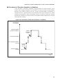
Figure 3.5-1 is used to show an example of mutex behavior when the priority inheritance
protocol is selected.
If Task C is running while the mutex is locked, the task priority is the same as the base priority
of Task C. If Task A, which has higher priority, is activated, Task A is executed. If Task A
tries to lock the mutex, Task A is transitioned into wait state and Task C is executed with the
task priority of Task A. Even if Task B transitions into ready state, it is not transitioned into run
state while Task C is running. Task C continues to run until it unlocks the mutex. The task
priority of Task C then returns to its normal priority, and Task A is executed.
Figure 3.5-1 Priority Inheritance Protocol
Task A (1)
Task B (2)
Task C (3)
Parentheses ( ) show base priority
tk_loc_mtx
tk_loc_mtx
Here, Task C's current
priority is increased
from 3 to 1.
Even if
Task B is
transitioned
into ready state, tk_unl_mtx
it is not executed.
tk_unl_mtx
Figure 3.5-2 is used to show an example of mutex behavior when the priority ceiling protocol
is selected.
Assume that the mutex ceiling protocol has the same priority as Task A. If Task C locks the
mutex, Task C continues to run with the same priority as Task A even if Tasks A and B are
transitioned into ready state. When Task C unlocks the mutex, its priority returns to its original
priority, and Task A is executed next, followed by Task B.
40
CHAPTER 3 μT-REALOS FUNCTIONS
Figure 3.5-2 Priority Ceiling Protocol
Task A (1)
Task B (2)
Task C (3)
Parentheses ( ) show base priority
tk_loc_mtx
Current priority is
increased from 3 to 1.
Tasks A and B are not
executed even if they
are transitioned into
ready state.
tk_unl_mtx
The lock is released
and priority is decreased
from 1 to 3.
41
CHAPTER 3 μT-REALOS FUNCTIONS
3.5.2
Message Buffer Functions
This section explains the message buffer functions.
■ Message Buffer Functions
Message buffers are objects that perform synchronization and communication by receiving
variable-length messages. Table 3.5-2 shows message buffer functions and their corresponding
system calls.
Table 3.5-2 Message Buffer Functions and Corresponding System Calls
Function
System Call Name
Create message buffer
tk_cre_mbf
Delete message buffer
tk_del_mbf
Send Message to Message Buffer
tk_snd_mbf
Receive Message from Message Buffer
tk_rcv_mbf
Refer Message Buffer Status
tk_ref_mbf
Message buffer objects are identified by an ID number. The message buffer ID number is
called the message buffer ID.
Message buffers have a wait queue of tasks waiting to send messages (send wait queue) and a
wait queue of tasks waiting to receive messages (receive wait queue). The message buffer also
has a message buffer area for storing sent messages.
The message-sending side (the event notifier side) copies the messages to be sent into the
message buffer. If there is not enough free space in the message buffer area, the task waits for
sending a message to message buffer until there is enough free space in the message buffer
area. Tasks waiting to send a message to message buffer are linked to the send wait queue of
that message buffer. The order of the send wait queue can be selected from the two options of
FIFO order (TA_TFIFO) and task priority order (TA_TPRI). This is specified as a part of
message buffer attributes when the message buffer is created.
The message-receiving side (the event wait side) retrieves a single message from the message
buffer. If there are no messages in the message buffer, the task waits for receiving a message
from message buffer until the next message is sent. Tasks waiting for receiving a message from
message buffer are linked to the receive wait queue of that message buffer. The order of the
receive wait queue is always the FIFO order.
Synchronous messaging functionality can be obtained by setting the size of the message buffer
area to zero. This means that both the sending task and the receiving task wait for each-other to
make the system call, and pass the message between them when both tasks have made the
system call.
The message buffer functions provide the following functions using the corresponding system
calls.
42
CHAPTER 3 μT-REALOS FUNCTIONS
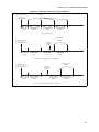
■ Additional Notes
Figure 3.5-3 shows the operation of a message buffer when the size of the message buffer area
is set to 0. In this diagram, Task A and Task B are executing asynchronously.
[Task A calls tk_snd_mbf first ((a) of Figure 3.5-3)]
Task A waits to send the message buffer until Task B calls tk_rcv_mbf. When Task B calls
tk_rcv_mbf, the message is transmitted from Task A to Task B.
Then, according to precedence, Tasks A and B are transitioned into run state or ready state.
[Task B calls tk_rcv_mbf first ((b) of Figure 3.5-3)]
Task B waits to receive the message buffer until Task A calls tk_snd_mbf. When Task A
calls tk_snd_mbf, the message is transmitted from Task A to Task B.
Then, according to precedence, Tasks A and B are transitioned into run state or ready state.
Figure 3.5-3 Synchronous Communication Using a Message Buffer
Task A
Task B
tk_snd_mbf
·
·
Send wait state
·
·
tk_rcv_mbf
(a) tk_snd_mbf called first
Task A
Task B
tk_rcv_mbf
·
·
Receive wait state
·
·
tk_snd_mbf
(b) tk_rcv_mbf called first
Tasks that are waiting to send to a message buffer send messages in the order that they are
linked to the wait queue. For example, consider the situation where Task A which is attempting
to send a 40-byte message to the message buffer and Task B which is attempting to send a 10byte message, and these tasks are linked into the wait queue in this order. Now suppose that 20
bytes of free space are created by another task receiving a message. In this situation, Task B is
unable to send its message until Task A sends its message.
Message buffers are different from mailboxes because they transfer variable-length messages
by copying.
43
CHAPTER 3 μT-REALOS FUNCTIONS
3.5.3
Rendezvous Port Functions
This section explains the rendezvous port functions.
■ Rendezvous Port Functions
Rendezvous ports provide intertask synchronous communication functionality, and support a
single sequence where one task requests processing of another task and the other task then
returns the processing result to the first task. The object that synchronizes the waiting of both
tasks is called a rendezvous port. Although the rendezvous port functions can be used to
implement a client/server model of intertask communication, they provide a synchronous
communication model that is more flexible than the client/server model. Table 3.5-3 shows
rendezvous port functions and their corresponding system calls.
Table 3.5-3 Rendezvous Port Functions and Corresponding System Calls
Function
System Call Name
Create Port for Rendezvous
tk_cre_por
Delete Port for Rendezvous
tk_del_por
Call Port for Rendezvous
tk_cal_por
Accept Port for Rendezvous
tk_acp_por
Reply Rendezvous
tk_rpl_rdv
Forward Rendezvous to Another Port
tk_fwd_por
Refer Port Status
tk_ref_por
Rendezvous port objects are identified by an ID number. The rendezvous port ID number is
called the rendezvous port ID.
The task that makes the processing request to the rendezvous port (the client-side task)
specifies the rendezvous port, rendezvous conditions, and a message containing information
regarding the processing being requested (called the call message) and calls the rendezvous
port. On the other hand, the task that accepts the processing request at the rendezvous port (the
server-side task) specifies the rendezvous port and rendezvous conditions, then accepts
processing at the rendezvous port. The rendezvous parameters are specified as a bit pattern. For
a given rendezvous port, a rendezvous is established if the result of logical bitwise ANDing of
the rendezvous parameters bit pattern of the calling tasking and the rendezvous parameters bit
pattern of the accepting task is non-zero. The task that calls the rendezvous port enters the
rendezvous call wait state until the rendezvous is established. Contrarily, the task that accepts
the processing request at the rendezvous port is in wait state until the rendezvous is established.
Once the rendezvous is established, the call message is passed from the task that called the
rendezvous port to the task that accepted the rendezvous. The task that called the rendezvous
port then enters the rendezvous completion wait state and waits for the requested processing to
finish. On the other hand, the wait state is released for the task that accepted the processing at
the rendezvous port, and the requested process is executed. When the task that accepted the
processing at the rendezvous port is completed, processing results are handed to the called task
44
CHAPTER 3 μT-REALOS FUNCTIONS
as a reply message, and the rendezvous is terminated. At this time, the task that called the
rendezvous port is released from the rendezvous completion wait state.
Rendezvous ports have a call wait queue for linking tasks in the rendezvous call wait state, and
a receive wait queue for linking tasks in the rendezvous accept wait state. When the rendezvous
is established, both tasks involved in establishing the rendezvous are detached. In other words,
the rendezvous port does not hold a wait queue to connect tasks waiting for a rendezvous to
terminate. Nor does it not hold information regarding processes accepted at the rendezvous port
or tasks running requested processes.
The kernel allocates object numbers for identifying rendezvous that are established at the same
time. The rendezvous object number is called the rendezvous number. The lower 16 bits of the
rendezvous number is the task ID of the task that called the rendezvous port, and the upper 16
bits is a sequential number that is incremented by 1 for each rendezvous accepted. This means
that even when rendezvous port are called by the same task, different rendezvous numbers are
allocated to the first rendezvous and the second rendezvous.
■ Additional Notes
Figure 3.5-4 shows the rendezvous operation. In this diagram, Task A and Task B are
executing asynchronously.
[Task A calls tk_cal_por first ((a) of Figure 3.5-4)]
Task A is in wait state for the rendezvous to be called until Task B calls tk_acp_por. The
rendezvous is established when Task B calls tk_acp_por, and Task A will be in wait state
for the rendezvous to terminate.
When Task B calls tk_rpl_rdv, Task A is released from wait state for the rendezvous to
terminate.
Then both tasks are transitioned to run state.
[Task B calls tk_acp_por first ((b) of Figure 3.5-4)]
Task B is in wait state for the rendezvous to accept until Task A calls tk_cal_por. The
rendezvous is established when Task A calls tk_cal_por, and Task A is in wait state for the
rendezvous to terminate, while Task B is released from wait state for the rendezvous to
accept.
When Task B calls tk_rpl_rdv, Task A is released from wait state for the rendezvous to
terminate.
Then both tasks are transitioned to run state.
45
CHAPTER 3 μT-REALOS FUNCTIONS
Figure 3.5-4 Rendezvous Operation
Task A
Task B
Task A
tk_cal_por
·
·
Call wait state
·
·
tk_acp_por
tk_cal_por
·
·
Completion wait state
Completion wait state
·
·
tk_rpl_rdv
(a) tk_cal_por called first
46
Task B
tk_acp_por
·
·
Accept wait state
·
tk_rpl_rdv
(b) tk_acp_por called first
CHAPTER 3 μT-REALOS FUNCTIONS
3.6
Memory Pool Management Functions
This section explains the memory pool management functions.
■ Memory Pool Management Functions
The memory pool management functions are functions for managing memory pools and
allocating regions of memory (memory blocks) for use by user programs.
The available memory pools are the fixed-size memory pool and the variable-size memory
pool. These two memory pools are separate objects and are accessed by different system calls.
While the size of memory blocks obtained from fixed-size memory pools are fixed, the size of
memory blocks obtained from variable-size memory pools can be specified.
The memory pool management functions support the following functions.
• Fixed-size memory pool functions
• Variable-size memory pool functions
47
CHAPTER 3 μT-REALOS FUNCTIONS
3.6.1
Fixed-size Memory Pool Functions
This section explains the fixed-size memory pool functions.
■ Fixed-size Memory Pool Functions
Fixed-size memory pool are objects that perform dynamic management of fixed size memory
blocks. Table 3.6-1 shows fixed-size memory pool functions and their corresponding system
calls.
Table 3.6-1 Fixed-Size Memory Pool Functions and Corresponding System Calls
Function
System Call Name
Create fixed-size memory pool
tk_cre_mpf
Delete fixed-size memory pool
tk_del_mpf
Get Fixed-size Memory Block
tk_get_mpf
Release Fixed-size Memory Block
tk_rel_mpf
Refer Fixed-size Memory Pool Status
tk_ref_mpf
The fixed-size memory pool objects are identified by an ID number. The fixed-size memory
pool ID number is called the fixed-size memory pool ID.
Fixed-size memory pool have a region of memory that is used as the fixed-size memory pool
(this is called the fixed-size memory pool region, or simply the memory pool region), and a
wait queue for tasks that are waiting to get a memory block. If there is no free space in the
memory pool region, a task that gets a memory block from a fixed-size memory pool enters the
fixed length memory block acquisition wait state until the next memory block is returned.
Tasks that enter the fixed length memory block acquisition wait state are linked to the wait
queue of that fixed-size memory pool. The order of the wait queue can be selected from the
two options of FIFO order (TA_TFIFO) and task priority order (TA_TPRI). This is specified
as a part of fixed-size memory pool attributes when the fixed-size memory pool is created.
Figure 3.6-1 Memory Region of a Fixed-size Memory Pool
· · ·
· · ·
Memory blocks (all the same size)
48
CHAPTER 3 μT-REALOS FUNCTIONS
3.6.2
Variable-size Memory Pool Functions
This section explains the variable-size memory pool functions.
■ Variable-size Memory Pool Functions
Variable-size memory pool are objects for dynamically managing arbitrary size memory
blocks. Table 3.6-2 shows variable-size memory pool functions and their corresponding system
calls.
Table 3.6-2 Variable-Size Memory Pool Functions and Corresponding System
Calls
Function
System Call Name
Create variable-size memory pool
tk_cre_mpl
Delete variable-size memory pool
tk_del_mpl
Get Variable-size Memory Block
tk_get_mpl
Release Variable-size Memory Block
tk_rel_mpl
Refer Variable-size Memory Pool Status
tk_ref_mpl
The variable-size memory pool objects are identified by an ID number. The variable-size
memory pool ID number is called the variable-size memory pool ID.
Variable-size memory pool have a region of memory that is used as the variable-size memory
pool (this is called the variable-size memory pool region, or simply the memory pool region),
and a wait queue for tasks that are waiting to get a memory block. If there is insufficient free
space in the memory pool region when a task gets a memory block from the variable-size
memory pool, the task enters the variable length memory block acquisition WAITING until a
memory block of sufficient size is returned. Tasks that enter the variable length memory block
acquisition WAITING are linked to the wait queue of that variable-size memory pool. The
order of the wait queue can be selected from the two options of FIFO order (TA_TFIFO) and
task priority order (TA_TPRI). This is specified as a part of variable-size memory pool
attributes when the variable-size memory pool is created.
Figure 3.6-2 Memory Region of a Variable-size Memory Pool
· · ·
· · ·
Memory blocks (sizes vary)
49
CHAPTER 3 μT-REALOS FUNCTIONS
3.7
Time Management Functions
This section explains the time management functions.
■ Time Management Functions
The time management functions are functions for performing time-dependent processing. The
functions include functions for system time management, cyclic handlers, and alarm handlers.
Cyclic handlers and alarm handlers are collectively referred to as time event handlers.
The time management functions support the following functions.
• System time management functions
• Cyclic handler functions
• Alarm handler functions
50
CHAPTER 3 μT-REALOS FUNCTIONS
3.7.1
System Time Management Functions
This section explains the system time management functions.
■ System Time Management Functions
System time management functions are used to update, set and reference the system time, as
well as to reference the system operating time. Table 3.7-1 shows system time management
functions and their corresponding system calls.
Table 3.7-1 System Time Management Functions and Corresponding System
Calls
Function
System Call Name
Signal Time
isig_tim
Set Time
tk_set_tim
Get Time
tk_get_tim
Get Operating Time
tk_get_otm
μT-REALOS uses isig_tim to update the system time for user programs. This system call
increases the system time by 1.
isig_tim is a system call unique to μT-REALOS.
Because resolution of system time is processed in units of 1ms, interrupts are made in 1ms
cycles using an interval timer. System time is updated by calling isig_tim from the interrupt
handler.
System operating time shows the elapsed time since the system was activated. Unlike system
time, it does not affect system time settings when tk_set_tim is called.
■ System Time
The system time is represented by the accumulated number of milliseconds since the 1st
January 1985 (GMT). For example, a system time value of 0 represents 12:00:00 AM on 1st
January 1985 (GMT). A system time value of 1000 represents 12:00:01 AM on 1st January
1985 (GMT). Because μT-REALOS does not have a function to automatically set the current
time when the system starts, the current time must be set by the user program.
51
CHAPTER 3 μT-REALOS FUNCTIONS
3.7.2
Cyclic Handler Functions
This section explains the cyclic handler functions.
■ Cyclic Handler Functions
Cyclic handlers are time event handlers that activate at a fixed period. Table 3.7-2 shows cyclic
handler functions and their corresponding system calls
Table 3.7-2 Cyclic Handler Functions and Corresponding System Calls
Function
System Call Name
Create cyclic handler
tk_cre_cyc
Delete cyclic handler
tk_del_cyc
tk_sta_cyc
Start cyclic handler
tk_cre_cyc
(Specify TA_STA to create and start cyclic
handler)
Stop cyclic handler
tk_stp_cyc
Refer Cyclic Handler Status
tk_ref_cyc
Cyclic handler objects are identified by an ID number. The cyclic handler ID number is called
the cyclic handler ID.
The activation interval and activation phase for each cyclic handler can be set when the cyclic
handler is created. When handling a cyclic handler, the kernel determines the time when the
cyclic handler should be activated next from the specified activation interval and activation
phase. When the time when the cyclic handler should activate is reached, the cyclic handler is
activated with the extended information (exinf) of that cyclic handler as a parameter. In this
case, the time when the handler should next activate is set to the time when the cyclic handler
should have activated plus the activation interval. When the operation of a cyclic handler is
started, the time when the handler should next activate may need to be reset.
Cyclic handlers can either be in the operating state or the non-operating state. When a cyclic
handler is in the non-operating state, the cyclic handler is not activated even when the time
when the cyclic handler is supposed to activate is reached, and only the time when the handler
should next activate is set. When the system call to start the operation of the cyclic handler
(tk_sta_cyc) is called, the cyclic handler is placed in the operating state and the time when the
cyclic handler should next activate is reset if necessary. When the system call to stop the
operation of the cyclic handler (tk_stp_cyc) is called, the cyclic handler changes to the nonoperating state. After the cyclic handler is created, either the operating or non-operating state is
determined by the cyclic handler attributes.
See Section "4.6 Cyclic Handler" for details on the format of cyclic handlers.
52
CHAPTER 3 μT-REALOS FUNCTIONS
Figure 3.7-1 Activation Timing for Cyclic Handlers
Create cyclic handler
tk_cre_cyc
(TA_STA present)
Activate cyclic
handler
Activation phase Activation interval
(cyctim)
(cycphs)
Activation interval
(cyctim)
Activation interval
(cyctim)
(a) TA_STA specified
Activate cyclic
handler
Create cyclic handler
tk_cre_cyc
(TA_STA not present)
Start cyclic
handler
tk_sta_cyc
Activation phase Activation interval
(cycphs)
(cyctim)
Activation interval
(cyctim)
Activation interval
(cyctim)
(b) TA_STA not specified, TA_PHS specified
Activate cyclic
handler
Create cyclic handler
tk_cre_cyc
(TA_STA not present)
Start cyclic
handler
tk_sta_cyc
Activation phase Activation interval
(cycphs)
(cyctim)
Activation interval
(cyctim)
Activation interval
(cyctim)
(c) TA_STA not specified, TA_PHS not specified
For details on TA_PHS, see "3.8.2.1 tk_cre_cyc(Create Cyclic Handler)" in "API Reference".
53
CHAPTER 3 μT-REALOS FUNCTIONS
3.7.3
Alarm Handler Functions
This section explains the alarm handler functions.
■ Alarm Handler Functions
Alarm handlers are time event handlers that activate at a specified time. Table 3.7-3 shows
alarm handlers functions and their corresponding system calls.
Table 3.7-3 Alarm Handlers Functions and Corresponding System Calls
Function
System Call Name
Create alarm handler
tk_cre_alm
Delete alarm handler
tk_del_alm
Start alarm handler
tk_sta_alm
Stop alarm handler
tk_stp_alm
Refer Alarm Handler Status
tk_ref_alm
Alarm handler objects are identified by an ID number. The alarm handler ID number is called
the alarm handler ID.
The time when an alarm handler activates (this is called the alarm handler activation time) can
be set for each alarm handler. When the alarm handler activation time is reached, the alarm
handler is activated with the extended information (exinf) of that alarm handler as a parameter.
Immediately after an alarm handler is created, the alarm handler activation time is not set and
the alarm handler is stopped. When the system call to start the operation of an alarm handler
(tk_sta_alm) is called, the alarm handler activates after the specified relative time. When the
system call to stop the operation of an alarm handler (tk_stp_alm) is called, the alarm handler
activation time setting is cleared. In addition, when an alarm handler activates, the alarm
handler activation time setting is cleared and the alarm handler is stopped.
See Section "4.7 Alarm Handler" for details on writing alarm handlers.
Figure 3.7-2 Activation Timing for Alarm Handlers
Create
alarm handler
tk_cre_alm
Start
alarm handler
tk_sta_alm
Activate
alarm handler
Relative time
until alarm handler is activated
54
Start
Stop
alarm handler alarm handler
tk_sta_alm
tk_stp_alm
Alarm handler is
not activated
CHAPTER 3 μT-REALOS FUNCTIONS
3.8
Interrupt Management Functions
This section explains the interrupt management functions.
■ Interrupt Management Functions
The interrupt management functions are functions for performing operations such as defining
handlers for external interrupts and system exceptions, and controlling interrupts. Table 3.8-1
shows interrupt management functions and their corresponding system calls.
Table 3.8-1 Interrupt Management Functions and Corresponding System Calls
Function
System Call Name
Define interrupt handler
tk_def_int
Return from interrupt handler
tk_ref_int
Prohibits all external interrupts
DI
Enables all external interrupts
EI
Checks the external interrupt disabled status
isDI
The interrupt management functions provide the following functions using the corresponding
system calls.
• System calls that specify the invoking task and system calls that enter a WAITING state
produce an error.
During execution in the task-independent portion, if a dispatch request is made during the
processing of a system call, the dispatch is delayed until the system leaves the task-independent
portion. This is called delayed dispatching.
See Section "4.8 Interrupt Handler" for details on writing interrupt handlers.
These functions manipulate the CPU registers to set the interrupts enabled/disabled. DI, EI, and
isDI cannot be called from the task-independent portion or from a state where dispatch and
interrupts are disabled.
55
CHAPTER 3 μT-REALOS FUNCTIONS
3.9
System State Management Functions
This section explains the system state management functions.
■ System State Management Functions
The system state management functions are functions for changing and referring to the state of
the system. Table 3.9-1 shows system state management functions and their corresponding
system calls.
Table 3.9-1 System State Management Functions and Corresponding System
Calls
Function
56
System Call Name
Rotate Ready Queue
tk_rot_rdq
Get Task Identifier
tk_get_tid
Disable dispatch
tk_dis_dsp
Enable dispatch
tk_ena_dsp
Refer System Status
tk_ref_sys
Refer Version Information
tk_ref_ver
CHAPTER 3 μT-REALOS FUNCTIONS
3.10
Subsystem Management Functions
This section explains the subsystem management functions.
■ Subsystem Management Functions
The subsystem management functions consist of the extended SVC handlers for accepting
requests. The subsystem management functions provide the following functions depending on
the corresponding system calls. Table 3.10-1 shows subsystem management functions and their
corresponding system calls.
Table 3.10-1 Subsystem Management Functions and Corresponding System
Calls
Function
System Call Name
Define subsystem
tk_def_ssy
Refer Subsystem Status
tk_ref_ssy
57
CHAPTER 3 μT-REALOS FUNCTIONS
3.11
Device Management Functions
This section explains the device management functions.
■ Device Management Functions
Device management functions provide a common API for handling different devices. Table
3.11-1 shows device management functions and their corresponding system calls.
Table 3.11-1 Device Management Functions and Corresponding System Calls
Function
System Call Name
Define Device
tk_def_dev
Refer Initial Device Information
tk_ref_idv
Open device
tk_opn_dev
Close device
tk_cls_dev
Read Device
tk_rea_dev
Synchronous Read Device
tk_srea_dev
Write Device
tk_wri_dev
Synchronous Write Device
tk_swri_dev
Wait Device
tk_wai_dev
Suspend device
tk_sus_dev
Get Device
tk_get_dev
tk_ref_dev
Get device information
tk_oref_dev
58
List Device
tk_lst_dev
Event Device
tk_evt_dev
CHAPTER 3 μT-REALOS FUNCTIONS
The system calls that can be called depending on the device registration and open state are as
follows.
Table 3.11-2 Callable System Calls
Device
registered
Device
opened
No
No
tk_def_dev
No
tk_opn_dev, tk_ref_idv, tk_get_dev, tk_ref_dev,
tk_lst_dev, tk_sus_dev, tk_def_dev
Yes
All system calls of the device management function
Yes
Callable system calls
The specifications for the interface between the device drivers and the kernel are defined by the
device driver interface. The device driver interface defines the device processing functions that
are called from the kernel, the format of data passed between the kernel and the device driver,
etc.
Because the device driver interface is supported by all μT-Kernel specification OSs, device
drivers that were created in compliance with device driver interface have improved portability
between μT-Kernel specification OSs.
See "CHAPTER 4 DEVICE DRIVER INTERFACE" of the "API Reference" for details on the
device driver interface.
59
CHAPTER 3 μT-REALOS FUNCTIONS
3.12
Power Saving Functions
This section explains the power saving functions.
■ Power Saving Functions
The μT-REALOS supports a function to call a user-defined power saving routine when it has
switched to the idle state. This is called the power saving function.
The processing performed by the power saving routine can be written freely by the user to suit
the target hardware. This power saving routine is useful because it is defined using the static
API of the configurator. See "3.13 Kernel Configuration Function" for details on how to define
the power saving routine and to "4.10 Power Saving Routine" for details on writing the power
saving routine.
60
CHAPTER 3 μT-REALOS FUNCTIONS
3.13
Kernel Configuration Function
This section explains the kernel configuration function.
■ Kernel Configuration Function
The kernel configuration function provide the functionality for the user to define the
configuration of the kernel, such as upper limits on the number of resources used by the kernel,
and to configure the internal kernel management data based on this. The amount of memory
used by the kernel can be reduced by optimizing the kernel configuration to suit the user
program. This also provides functions for statically registering user program modules such as
interrupt handlers and the initial routine.
A definition statement used to register user program modules in the kernel configuration
function is called a "static API".
When kernel configuration is executed, the configuration definition macros and static API are
written in a text format file called the "configuration file", and the Configurator is executed
with this as the input file.
Configurator takes the configuration file as the input file and outputs the kernel configuration
file in the library format. The kernel configuration file must be linked with the user program
when an object of the executable format is created.
See Section "5.2 Kernel Configuration" for details on how to execute the configurator and
parameters during exection.
61
CHAPTER 3 μT-REALOS FUNCTIONS
■ Configuration Definition Macros
The configuration definition macros are macros provided for user-defined kernel
configurations. A list of the configuration definition macros is given below.
Table 3.13-1 List of Configuration Definition Macros
Function
type
Name
_KERNEL_MAX_TSKPRI
Priority
_KERNEL_INIT_TSKPRI
definitions
_KERNEL_MAX_SSYPRI
Meaning
Maximum task priority
1 to 1024
Initial task priority
1 to 1024
Maximum subsystem priority
1 to 16
_KERNEL_USE_TKDEFINT Use or not use tk_def_int (1 means use)
Function
selection
62
0 or 1
_KERNEL_USE_IMALLOC
Use or not use the heap area (1 means use) 0 or 1
_KERNEL_USE_DEVT
Use or not use the device management
functions (1 means use)
0 or 1
_KERNEL_REALMEMSZ
Size of the heap area
Any value (0)
_KERNEL_MAX_TSK
Maximum number of tasks
1 to 32767
_KERNEL_MAX_SEM
Maximum number of semaphores
0 to 32767
_KERNEL_MAX_FLG
Maximum number of event flags
0 to 32767
_KERNEL_MAX_MBX
Maximum number of mailboxes
0 to 32767
_KERNEL_MAX_MTX
Maximum number of mutexes
0 to 32767
_KERNEL_MAX_MBF
Maximum number of message buffers
0 to 32767
_KERNEL_MAX_POR
Maximum number of rendezvous ports
0 to 32767
Maximum number of fixed-size memory
pool
0 to 32767
Maximum _KERNEL_MAX_MPF
number of
each object _KERNEL_MAX_MPL
Size
specified
Range of values
(default values
shown in bold)
Maximum number of variable-size memory
0 to 32767
pool
_KERNEL_MAX_CYC
Maximum number of cyclic handlers
0 to 32767
_KERNEL_MAX_ALM
Maximum number of alarm handlers
0 to 32767
_KERNEL_MAX_SSY
Maximum number of subsystems
0 to 255
_KERNEL_MAX_REGDEV
Maximum number of registered devices
0 to 255
_KERNEL_MAX_OPNDEV
Maximum number of open devices
0 to 255
_KERNEL_MAX_REQDEV
Maximum number of device requests
0 to 255
_KERNEL_MAX_VCT
Maximum number of interrups
16 to 256
_KERNEL_SYS_STKSIZE
System stack size
0x80 to 0xfffffffc
_KERNEL_INIT_TSKSTKSZ Initial task stack size
0x80 to 0xfffffffc
_KERNEL_DEVT_MBFSZ0
Message buffer size for event notification
0 to 0xfffffffc
_KERNEL_DEVT_MBFSZ1
Maximum message buffer size for event
notification
0 to 0xfffffffc
CHAPTER 3 μT-REALOS FUNCTIONS
The value of "_KERNEL_MAX_TSKPRI" and the value of "_KERNEL_INIT_TSKPRI" must
satisfy the following condition.
value of "_KERNEL_MAX_TSKPRI" ≥ value of "_KERNEL_INIT_TSKPRI"
The value of "_KERNEL_MAX_SEM" and the value of "_KERNEL_MAX_OPNDEV" must
satisfy the following condition.
value of "_KERNEL_MAX_SEM" ≥ value of "_KERNEL_MAX_OPNDEV"
_KERNEL_REALMEMSZ specifies the size of the heap area. If the attribute of the
TA_USERBUF is not specified upon creation of the task, the message buffer, or the memory
pool, the task stack, the message buffer area, or the memory pool area can be automatically got
from the heap area.
If the definition of any of the configuration definition macros is omitted, the minimum value that
can be taken is selected as the default value. For example, if the definition of
"_KERNEL_MAX_TSKPRI" is omitted, the maximum value of the task priority is set to 1.
Similarly, if the definition of "_KERNEL_MAX_SEM" is omitted, the maximum number of
semaphores is set to 0.
If the maximum number of an object is 0, that object cannot be used. For example, if the
maximum number of semaphores is set to 0 and the user program contains semaphore-related
system calls, an undefined error occurs for the semaphore-related system calls when the user
system is built.
The configuration definition macros are written in the configuration file using the following
syntax.
[Configuration Definition Macro Syntax]
Configuration definition macro
Defined value
Example)
_KERNEL_MAX_TSK
256
_KERNEL_INIT_TSKSTKSZ
0x1000
Notes:
• The maximum number of tasks defined by "_KERNEL_MAX_TSK" includes the initial
task that is created within the kernel. Therefore, when the number of tasks that a user
program creates is N, define the maximum number of tasks as (N+1) or more.
• Because the device management function uses the following objects, set the value for
the maximum number of objects to "number used by user program + number used by
device management".
- Semaphores
: One used for each device opened
- Message buffers : One used by all device management functions
- Event flags
: One used by all device management functions
63
CHAPTER 3 μT-REALOS FUNCTIONS
■ Static API
The interface for the user program modules that are statically defined by the Configurator is
called the static API.
The static API can register the initialization routine, interrupt handlers, error routine, and
power saving routine. Furthermore, interrupt handlers can also be registered from a user
program using tk_def_int.
A list of the static API is shown in Table 3.13-2.
Table 3.13-2 List of Static API
Name
Function
ATT_INI
Defines the initial routine
DEF_INH
Defines an interrupt handler
VATT_ERR
Defines the error routine
VDEF_PSR
Defines a power saving routine
The static API is written in the configuration file using the following syntax.
[Static API Syntax]
• ATT_INI
ATT_INI({Attributes, Extended Information, Entry address});
Attributes:
Specify TA_HLNG.
Extended Information:
This is ignored for the current version.
Entry address:
Specify the entry address of initial routine.
• DEF_INH
DEF_INH(Interrupt Vector Number, {Attributes, Entry address});
Interrupt Vector Number:
A value from 0 to 255 can be specified. However, you cannot specify the number
defined with "_KERNEL_MAX_VCT" or more. Furthermore, the interrupt numbers
0, 7 to 10, 13 and 14 are reserved by the system.
Attributes:
Specify TA_HLNG. Specify VTA_SRSV to specify the interrupt numbers reserved
by the system.
Entry address:
Specify the entry address of interrupt handler.
• VATT_ERR
VATT_ERR({Attributes, Entry address});
Attributes:
Specify TA_HLNG.
Entry address:
Specify the entry address of error routine.
64
CHAPTER 3 μT-REALOS FUNCTIONS
• VDEF_PSR
VDEF_PSR({Attributes, Entry address});
Attributes:
Specify TA_HLNG.
Entry address:
Specify the entry address of power saving routine.
Example)
ATT_INI({ TA_HLNG, 0, uint});
DEF_INH(35, { TA_HLNG, inthdr});
VATT_ERR({TA_HLNG, uerr});
VDEF_PSR({TA_HLNG, pow_down});
65
CHAPTER 3 μT-REALOS FUNCTIONS
■ Setting of Configuration
Define the following items at Kernel configuration function.
• Definition of the maximum number of objects
Set the maximum value for the number of objects that the user program uses. The objects
can be created up to this maximum value and used in the user program. Therefore, define
the maximum value using a value bigger than the number of objects that are used in the
user program.
For example, when 3 semaphores are used in the user program, define the configuration
specification macro "_KERNEL_MAX_SEM" as 3. In such a case, the program can operate
without problems even it is defined as 10. However, since 10 semaphore control areas are
ensured in kernel, the 7 unused control areas will become useless. Therefore, it is necessary
to define the maximum number of objects used in application in order to optimize usage
efficiency of memory.
It is unnecessary to define objects not used in the user program.
Table 3.13-3 displays number of bytes of memory consumed in kernel for each object.
Table 3.13-3 Consumed Memory of Object Management Block
Object name
Management area size
(byte)
Task
_KERNEL_MAX_TSK
106
Semaphore
_KERNEL_MAX_SEM
24
Event Flag
_KERNEL_MAX_FLG
20
Mailbox
_KERNEL_MAX_MBX
24
Mutex
_KERNEL_MAX_MTX
26
Message Buffer
_KERNEL_MAX_MBF
48
Rendezvous Port
_KERNEL_MAX_POR
32
Fixed-size Memory Pool
_KERNEL_MAX_MPF
44
Variable-size Memory Pool
_KERNEL_MAX_MPL
48
Cyclic Handler
_KERNEL_MAX_CYC
40
Alarm Handler
_KERNEL_MAX_ALM
36
Subsystem
_KERNEL_MAX_SSY
4
_KERNEL_MAX_REGDEV
72
_KERNEL_MAX_OPNDEV
68
_KERNEL_MAX_REQDEV
50
Device
66
Configuration
specification macro
CHAPTER 3 μT-REALOS FUNCTIONS
For definition of maximum number of object, see "■ Configuration Definition Macros" in this
section.
• Definition of priority maximum value
Defines the maximum priority value of a task and subsystem. Similar to the maximum
object value, when the value defined for the task priority becomes smaller, consumed
memory of kernel can be reduced. When Task Priority is P, its consumed memory can be
calculated according to following formula.
Consumed Memory (byte) = (8 × P) + 4 × (P /32)
• Definition of system stack size and stack size of the initial task
Specifies the size of system stack and stack size of initial task. For specification method of
these stack sizes, see "■ Configuration Definition Macros" in this section.
• Registration of the initial routine and error routine
When using the initialization routine or error routine, perform the registration through the
static API. For registration method of these routines, see "■ Configuration Definition
Macros", "4.4 Initial Routine" in this section, and "4.9 Error Routine".
• Registration of an Interrupt Handler
On using an interrupt handler, register it through a static API. After the system startup,
dynamic registration of interrupt handler through tk_def_int is also available. In the case of
dynamic registration, registration through a static API will be not necessary. In addition, in
such a case, define "_KERNEL_USE_TKDEFINT" of configuration definition macro as 1.
On using an interrupt vector table located in the ROM area, setting
"_KERNEL_USE_TKDEFINT" to "0" will allow the kernel to cancel copying the vector
table from the ROM to the RAM. Therefore, memory used by the kernel can be reduced.
Whether to register an interrupt handler through a static API or tk_def_int is optional
depending on processing of the user program. Registration through a static API has
advantages in reducing the codes for operation of registration through tk_def_int.
67
CHAPTER 3 μT-REALOS FUNCTIONS
68
CHAPTER 4
WRITING A USER
PROGRAM
This chapter describes the basic items in
writing a user program on μT-REALOS.
4.1 Configuring a User Program
4.2 Activation Flow
4.3 Reset Entry Routine
4.4 Initial Routine
4.5 Task
4.6 Cyclic Handler
4.7 Alarm Handler
4.8 Interrupt Handler
4.9 Error Routine
4.10 Power Saving Routine
4.11 Extension SVC Handler
4.12 Device Driver
4.13 Notes when Writing a User Program
69
CHAPTER 4 WRITING A USER PROGRAM
4.1
Configuring a User Program
This section explains how to configure a user program.
■ Configuring a User Program
A user program consists of the modules in Table 4.1-1. Build the user system after creating
modules necessary for the user system.
Table 4.1-1 User Program Configuration Elements
Module name
Processing overview
Necessity
Reset entry routine
This routine is first launched by the hardware reset.
It performs hardware initialization, and starts the
kernel.
Mandatory
Initial routine
This routine is called from the kernel intialization.
It provides the operating environment for the user
program.
Mandatory
Task
Performs the main process of a user program.
Mandatory
Cyclic handler
Created when performing a process at regular time
intervals.
Optional
Alarm handler
Created if there is a process to be performed after a
certain time.
Optional
Created when handling hardware interrupts. When
system time is used, it is necessary to create a timer
interrupt handler.
Optional
Error routine
Created when handling kernel errors from a user
program.
Optional
Power saving routine
Created when performing power saving process
using a user program.
Optional
Extension SVC
Handler
Created when defining user function using the
extension SVC handler.
Optional
Device driver
Created when controlling the device driver using
the device management API.
Optional
Interrupt handler
For more on these, see "4.3 Reset Entry Routine" to "4.12 Device Driver" in this document
respectively.
70
CHAPTER 4 WRITING A USER PROGRAM
4.2
Activation Flow
This section explains the process flow from the hardware reset occurrence
until control is passed to the user program task.
■ Starting a User Program
Figure 4.2-1 shows the processing flow after hardware reset occurs.
When the initial routine of a user program is called by the initial task, control is passed to the
user program having the highest priority task.
Figure 4.2-1 Start Flow
Reset
User
program
Reset entry
routine
Processes, such as
initialization of
hardware
Jump to the
kernel
Kernel
Initialize the kernel
Initial task
Initialize the inside of the kernel
Initialize the device, etc.
Create an initial task
Initial routine
Start the initial task
Create a task, etc.
Call the initial routine
Return
Pass control to the user task having the highest priority
User task
Process the
user program
71
CHAPTER 4 WRITING A USER PROGRAM
4.3
Reset Entry Routine
This section explains how to write the reset entry routine.
■ Reset Entry Routine
The reset entry routine, which is launched by reset, performs initialization of the processor and
of the peripheral devices for which initial settings are necessary during reset. Control is then
moved to μT-REALOS.
■ Process of Reset Entry Routine
The reset entry routine generally performs the following processes:
• Initializing the data area (the ARM library) (mandatory)
Calls __main function of the C library and performs the following processing.
1. Copies nonroot (Read Only and Read Write) execution areas into each load address.
2. BSS (Block Started by Symbol) area is initialized by 0.
3. Branches into __rt_entry.
Figure 4.3-1 Initialization Flow in Data Area
Reset entry
routine
ARM library
Start
__main
Copies nonroot
execution area
to load address
BSS area initialized
by 0
__rt_entry
End
72
CHAPTER 4 WRITING A USER PROGRAM
• Setting the privileged mode, MSP (mandatory)
Performs the following processing.
1. Sets the privileged mode.
2. Sets the main stack address used while the kernel and the exception handler are operating
to the MSP register.
• Starting the kernel (mandatory)
Starts the kernel, allowing it to jump to the label of "knl_start_main" by the BX command of
the assembly language.
73
CHAPTER 4 WRITING A USER PROGRAM
■ A specific Example of the Reset Entry Routine
The description examples for each process of the reset entry routine are shown below. The
source codes are attached to the product as a sample program (icrt0.asm) of μT-REALOS.
• Initializing the data area (the ARM library)
Calls the main function and initializes the data area. Initialization processing of the ARM
library is not performed in the following description example. See "ARM Developer Suite
Compiler and Library Guide" of ARM for details on __main function processing.
Figure 4.3-2 Description Example of Initializing the Data Area (the ARM Library)
;; ---------------------------------------------;; Copy R0/RW area
;; Initialize ZI(BSS) area
;; ---------------------------------------------IMPORT __main
B
__main
EXPORT __rt_entry
__rt_entry
• Setting the privileged mode, MSP
In the following example, the mode is set as the privileged mode (μT-REALOS always
operates in the privileged mode), and the address of the main stack is set in the MSP register.
Figure 4.3-3 Description Example of Setting the privileged mode, MSP
;; ---------------------------------------------;; MSP setting
;; ----------------------- ----------------------mov
r0, #0
; Use MSP stack (privileged mode)
msr
control, r0
isb
ldr
msr
r0, =_kernel_MSP_stack_top ; Set main stack address
msp, r0
• Starting the kernel
Jumps to the label of "knl_start_main" to start the kernel.
Figure 4.3-4 Description Example of Starting the kernel
;; ---------------------------------------------;; Initialize kernel
;; ---------------------------------------------IMPORT knl_start_main
ldr
ip, = knl_start_main
mov
r0, #0
bx
ip
74
CHAPTER 4 WRITING A USER PROGRAM
4.4
Initial Routine
This section explains how to write the initialization routine.
■ Process of the Initial Routine
The initial routine is called from the initial task created during initialization of the kernel.
Although the initial routine can be described freely in accordance with the user program, it
generally performs the following processes:
• Creating and starting objects necessary for operations of the user program, such as tasks,
semaphores, time event handlers
• Initializing and registering device drivers
• Initializing hardware
• Starting a timer interrupt
Note:
The initial routine is executed while the interrupt is enabled.
■ Description Format of the Initial Routine
The initial routine is described as follows:
Figure 4.4-1 Description Format of the Initial Routine
void sample_init(void)
{
/*
Process the initial routine
*/
return;
}
75
CHAPTER 4 WRITING A USER PROGRAM
■ Description Example of the Initial Routine
Figure 4.4-2 shows the description example of the initial routine. The source codes are attached
to the product as a sample program (init_task.c) of μT-REALOS.
In the following example, after the timer for the system clock is started (SysTick_init()),
semaphore and three tasks (task ID=tsk1, tsk2, tsk3) are created. Then, the created three tasks
are started.
Figure 4.4-2 Description Example of the Initialization Routine
void uinit_task(void)
{
ID tsk1
ID tsk2
ID tsk3
T_CTSK ctsk;
T_CSEM csem;
static INT task1_stack[0x400/4];
static INT task2_stack[0x400/4];
static INT task3_stack[0x400/4];
/*symtem clock set*/
SysTick_init();
csem.sematr
= TA_TFIFO | TA_FIRST;
csem.isemcnt = 0;
csem.maxsem = 1;
sem1 = tk_cre_sem(&csem);
/* Create semaphore */
ctsk.exinf
= (VP)1;
ctsk.tskatr
= TA_HLNG | TA_USERBUF;
ctsk.task
= task1;
ctsk.itskpri
= 1;
= (W)sizeof(task1_stack);
ctsk.stksz
ctsk.bufptr
= task1_stack;
tsk1 = tk_cre_tsk(&ctsk);
/* Create task1 */
ctsk.exinf
= (VP)2;
ctsk.tskatr
= TA_HLNG | TA_USERBUF;
ctsk.task
= task1;
ctsk.itskpri
= 2;
ctsk.stksz
= (W)sizeof(task2_stack);
= task2_stack;
ctsk.bufptr
tsk2 = tk_cre_tsk(&ctsk);
/* Create task2 */
ctsk.exinf
= (VP)3;
ctsk.tskatr
= TA_HLNG | TA_USERBUF;
ctsk.task
= task2;
ctsk.itskpri
= 3;
ctsk.stksz
= (W)sizeof(task3_stack);
ctsk.bufptr
= task3_stack;
tsk 3 = tk_cre_tsk(&ctsk);
/* Create task3 */
tk_sta_tsk(tsk1, 1);
tk_sta_tsk(tsk2, 2);
tk_sta_tsk(tsk3, 3);
}
76
/* Start task1 */
/* Start task2 */
/* Start task3 */
CHAPTER 4 WRITING A USER PROGRAM
4.5
Task
This section explains how to write a task.
■ Description Format of the Task
The task is described as follows:
Figure 4.5-1 Description Format of the Task
void task(INT stacd, VP exinf)
{
/*
Process the body of the task program
*/
tk_ext_tsk(); or tk_exd_tsk(); /* Task termination */
}
The following values are passed to dummy parameters stacd and exinf respectively.
stacd: The task start code specified during task startup (tk_sta_tsk).
exinf: The extension information specified when the task is created (tk_cre_tsk).
A function(task) cannot be terminated by a simple return. Using tk_ext_tsk or tk_exd_tsk to
ensure termination.
■ Creating a Task
tk_cre_tsk is called to create a task. In the following example, function, "task1", is being
created using task priority 1. If tk_cre_tsk is terminated normally, the task ID will be returned
as the return value.
Figure 4.5-2 Description Example of Task Creation
ID tid1;
/* Task ID of task1 */
T_CTSK ctsk;
/* Input parameter of tk_cre_tsk */
INT task1_stack[256]; /* Stack area of the task */
ctsk.exinf = (VP)1;
/* Extension information=1 */
ctsk.tskatr = TA_HLNG | TA_USERBUF; /* Attribute */
ctsk.task = task1;
/* Start address of the task */
ctsk.itskpri = 1;
/* Task priority */
ctsk.stksz = (W)sizeof(task1_stack); /* Stack size */
ctsk.bufptr = task1_stack;
/* Start address of the stack */
tid1 = tk_cre_tsk(&ctsk);
/* Create the task */
For details of tk_cre_tsk, see "3.3.1 tk_cre_tsk" of "API Reference" .
77
CHAPTER 4 WRITING A USER PROGRAM
■ Starting a Task
A task created by tk_cre_tsk is initially in the stop status. Therefore, tk_sta_tsk is called to run
this task. In the example below, the task whose task ID is tid1 is being started.
Figure 4.5-3 Description Example of the Task Startup
tk_sta_tsk(tid1, 1);
/* Start the task whose task ID is tid1 */
The status of a task started by tk_sta_tsk is executable. If the priority of a task is higher than
those of other tasks of execution status or executable status, the task attains execution status.
For details of tk_sta_tsk, see "3.3.3 tk_sta_tsk" of "API Reference".
■ A specific Example of the Task
Figure 4.5-4 shows the description example of a task, and Figure 4.5-5 shows the operation
diagram of the program in the description example. The source codes are attached to the
product as a sample program (init_task.c) of μT-REALOS. In addition, the task in this specific
example is created/started using the initial routine given in Figure 4.4-2.
In Figure 4.5-4, task1 and task2 move to the status of waiting for the semaphore of sem1 by
tk_wai_sem. task3 releases the semaphore resources of sem1 by the system call of tk_sig_sem.
This releases task1 and task2 from the waiting status. The task priorities are: task1 > task2 >
task3.
78
CHAPTER 4 WRITING A USER PROGRAM
Figure 4.5-4 Description Example of a Task
static void task1( INT stacd, VP exinf )
{
if(stacd == 1){
while (1) {
tk_wai_sem(sem1, 1, TMO_FEVR);
}
}
else{
tk_ext_tsk();
/* Exit task */
}
}
static void task2( INT stacd, VP exinf )
{
if(stacd == 2){
while (1) {
tk_wai_sem(sem1, 1, TMO_FEVR);
}
}
else{
tk_ext_tsk();
/* Exit task */
}
}
static void task3( INT stacd, VP exinf )
{
if (stacd == 3){
while (1) {
tk_sig_sem(sem1, 1);
}
}
else{
tk_e xt_tsk();
/* Exit task */
}
}
Figure 4.5-5 Operation Diagram of the Description Example
wai _sem
wai _sem
t ask1
wai _sem
task2
wai _sem
task3
sig_sem
sig_sem
Time
79
CHAPTER 4 WRITING A USER PROGRAM
Note:
While dispatch is on hold, the state transition is delayed until the state enters into where
dispatch occurs, when moving the tasks during execution to the forcible waiting state and
the stop state. In such a case, although tasks being executed will retain the execution
status, the processing of transition to the forcible waiting state or the stop state is already
being executed.
80
CHAPTER 4 WRITING A USER PROGRAM
4.6
Cyclic Handler
This section explains how to write a Cyclic handler.
■ Description Format of a Cyclic Handler
The cyclic handler is described as follows:
Figure 4.6-1 Description Example of a Cyclic Handler
void cychdr1(VP exinf)
{
/* Process the Cyclic handler */
return; /* Terminate the Cyclic handler */
}
■ Creation of a Cyclic Handler
tk_cre_cyc is called to create a cyclic handler. In the example below, a cyclic handler with the
start period of 1 second (1000ms) for the function "cychdr1" is created. When creation of a
cyclic handler normally ends, the cyclic handler ID is returned as the return value.
Figure 4.6-2 Description Example of the Cyclic Handler Creation
ID cycid1;
/* Cyclic handler ID */
T_CCYC ccyc;
/* Input parameter of tk_cre_cyc*/
ccycexinf
= (VP)1;
ccyc.cycatr = TA_HLNG | TA_STA;
ccyc.cychdr = cychdr1;
ccyc.cyctim = 1000;
ccyc.cycphs = 0;
cycid1 = tk_cre_cyc(&ccyc);
/* Extension information=1 */
/* Attribute */
/* Start address of the Cyclic handler */
/* Start Cyclic */
/* Start phase */
/* Create the Cyclic handler */
When specifying TA_STA for attribute, a cyclic handler becomes the action status after it was
created. After the start period elapses, a cyclic handler is called. If not specifying TA_STA, a
cyclic handler becomes the stop status after it was created.
Specifying TA_HLNG for attribute indicates the target cyclic handler is written in C. Be sure
to specify TA_HLNG.
■ Launch of a Cyclic Handler
A Cyclic handler is moved from the stop status to the action status, when tk_sta_cyc is called.
In the following example, the cyclic handler is started as the Cyclic handler ID of cycid1.
Figure 4.6-3 Description Example of the Cyclic Handler Startup
tk_sta_cyc(cycid1); /* Start the Cyclic handler whose ID is cycid1 */
81
CHAPTER 4 WRITING A USER PROGRAM
4.7
Alarm Handler
This section explains how to write an alarm handler.
■ Description Format of an Alarm Handler
An alarm handler is described as follows:
Figure 4.7-1 Description Example of an Alarm Handler
void almhdr1(VP exinf)
{
/* Process the alarm handler */
return; /* Terminate the alarm handler */
}
The extension information specified when an alarm handler is created (tk_cre_alm) is passed to
exinf.
■ Creating an Alarm Handler
tk_cre_alm is called to create an alarm handler. In the following example, function "almhdr1"
is created as an alarm handler. If creation of an alarm handler is terminated normally, the alarm
handler ID will be returned as the return value.
An alarm handler moves to the stop status after it is created.
Figure 4.7-2 Description Example of the Alarm Handler Creation
ID almid1;
T_CALM calm;
/* Alarm handler ID*/
/* Input parameter of tk_cre_alm*/
calm.exinf = (VP)1;
calm.almatr = TA_HLNG;
calm.almhdr = almhdr1;
almid1 = tk_cre_alm(&calm);
/*Extension information =1 */
/* Attribute */
/* Start address of the alarm handler */
/* Create the alarm handler */
■ Starting an Alarm Handler
An alarm handler is moved from the stop status to the action status, when tk_sta_alm is called.
The following example activates Alarm Handler ID:almid1 in 100ms.
Figure 4.7-3 Description Example of the Alarm Handler Startup
tk_sta_alm(almid1, 100); /* activates Alarm Handler ID:
almid1 in 100ms. */
82
CHAPTER 4 WRITING A USER PROGRAM
4.8
Interrupt Handler
This section explains how to write an interrupt handler.
■ Description Format of an Interrupt Handler
An interrupt handler is described as follows:
Figure 4.8-1 Description Example of an Interrupt Handler
void sample_inthdr( void)
{
/* Interrupt handler body */
}
The interrupt handler is executed at the task independent portion. In addition, it is started while
interrupt is enabled. Therefore, while an interrupt handler is being executed, the interrupt
handler may be started multiply. For details, see "CHAPTER 5 EXCEPTION" of "Cortex-M3
Technical Reference Manual".
Note:
To activate the interrupt handler, a 32-byte stack is automatically consumed for each 1level interrupt. Bear this in mind when you are to design the system stack size.
■ Registering an Interrupt Handler
An interrupt handler can be registered in the following two ways.
• Register an interrupt handler during kernel configuration using static API "DEF_INH". To
perform operations with the vector table placed in the ROM, register an interrupt handler
using static API.
In the example below, the timer interrupt handler of vector number 15 "SysTick_Handler" is
registered as an interrupt handler.
Figure 4.8-2 Example of Registering an Interrupt Handler Using Static API
DEF_INH(15, {TA_HLNG|VTA_SRSV, SysTick_Handler });
• Call tk_def_int from a user program to dynamically register an interrupt handler.
Before executing kernel configuration, set "_KERNEL_USE_TKDEFINT" of the
configurator specification macro to 1.
In the example below, the timer interrupt handler of vector number 15 "SysTick_Handler" is
registered as an interrupt handler.
83
CHAPTER 4 WRITING A USER PROGRAM
Figure 4.8-3 Example of Registering an Interrupt Handler Through a User Program
T_DINT dint;
ER err;
dint.intatr = TA_HLNG|;
/* Attribute */
dint.inthdr = SysTick_Handler; /* Start address of the interrupt handler */
err = tk_def_int(15, &dint);
/* Register the interrupt handler */
■ Timer Interrupt Handler
To use the functions of time event handler, timeout, and system time, it is necessary to let the
timer interrupt occur at intervals of 1ms, and then update the system time using the interrupt
handler. System time will be updated when isig_tim is called.
A sample program (init_task.c) included with μT-REALOS uses system exception SysTick
timer for the timer interrupt handler.
An example of the timer interrupt is shown below.
Figure 4.8-4 Description Example of an Timer Interrupt Handler
EXPORT void SysTick (void)
{
/*
Clear the timer interrupt factors
*/
isig_tim();
}
Notes:
• When an interrupt handler is described using assembler, note the following points:
- Calling an interrupt handler or returning from an interrupt handler is not via the OS.
- As the OS does not back up and restore registers or perform stack settings, perform
such processes on the interrupt handler side.
• A time event handler is executed according to the interrupt priority of an interrupt
handler for system clock calling isig_tim.
• As the SysTick timer stops while the standby mode is set, neither time event handler
activation nor system time increment is not performed.
See "4.10 Power Saving Routine" for details on SysTick timer operation while the
power saving mode is set.
84
CHAPTER 4 WRITING A USER PROGRAM
4.9
Error Routine
This section explains how to write an error routine.
■ Description Format of an Error Routine
The description format of an error routine is shown as follows:
Figure 4.9-1 Description Format of an Error Routine
void sample_errrtn (UINT errptn, INT errinf1,INT errinf2)
{
/* Error routine body */
}
The kernel sets the following information to errptn, errinf1, and errinf2 and calls them.
• errptn : Error factor
= _KERNEL_ERR_SYS_DOWN (0x01): System down
= _KERNEL_ERR_INI_ERR (0x02): Initial setting error
= _KERNEL_ERR_EIT_DOWN (0x04): Undefined interrupt
• errinf1 : Error information1
In the case of [_KERNEL_ERR_SYS_DOWN ]
= 0x1 : tk_ext_tsk was called from the task independent portion.
= 0x2 : tk_exd_tsk was called from the task independent portion.
= 0x3 : tk_ext_tsk had been called while dispatch was disabled.
= 0x4 : tk_exd_tsk had been called while dispatch was disabled.
In the case of [_KERNEL_ERR_INI_ERR ]
Initial setting error information
= 0x1 : Heap area assignment error
= 0x2 : System startup error
= 0x3 : Initial task startup error
= 0x4 : Module initialization error
= 0x5 : Power off processing error
In the case of [_KERNEL_ERR_EIT_DOWN]
Uncertain value
• errinf2 : Error information2
Not used. Reserved for future extension.
■ Registering an Error Routine
For registering an error routine, see "3.13 Kernel Configuration Function".
85
CHAPTER 4 WRITING A USER PROGRAM
4.10
Power Saving Routine
This section explains how to write a power saving routine.
■ Description Format of a Power Saving Routine
The power saving routine is a process called when the status has become idle inside the kernel.
The processing of transition to the power saving mode is described inside a function.
A power saving routine is described as follows:
Figure 4.10-1 Description Example of a Power Saving Routine
void usr_low_pow ( void )
{
/* Describe the process of transition to the power saving mode*/
}
Notes:
• The FM3 Family supports the following three power saving modes.
- SLEEP
- TIMER
- STOP
• While TIMER and STOP modes are operating, the SysTick timer also stops.
• See "CHAPTER 5 LOW POWER CONSUMPTION MODE" of "MB9Axxx/MB9Bxxx
Series Peripheral Manual" for details on the power saving modes.
■ Registering a Power Saving Routine
For registering a power saving routine, see "■ Static API" in "3.13 Kernel Configuration
Function".
Note:
When a system call is made inside the power saving routine, the operation is not
guaranteed.
86
CHAPTER 4 WRITING A USER PROGRAM
4.11
Extension SVC Handler
This section explains how to create and call an extension SVC handler.
■ Description Format of an Extension SVC Handler
An extension SVC handler is described as follows:
Figure 4.11-1 Description Format of an Extension SVC Handler
INT svchdr(VP pk_para, FN fncd)
{
/*
Branch and proceed according to fncd
*/
return retcode; /*Terminate the extension SVC handler */
}
The following values are passed to parameters pk_para and fncd respectively.
pk_para : Turns the parameters passed from the caller into the packet format. The packet
format can be determined by a user who creates subsystems arbitrarily.
fncd :
A function code which contains the subsystem ID in its lower 8 bits. The
remaining higher bits are determined by a user who creates subsystems arbitrarily.
■ Calling Format of an Expansion SVC Handler
An extension SVC handler is called from call_EX_SVC function in a user program. An
extension SVC handler with an ID specified by fncd is called. It is described as follows:
Figure 4.11-2 Calling Format of an Expansion SVC Handler
call_EX_SVC(VP pk_para , FN fncd);
In the example below, the SVC handler whose subsystem ID (sayid) is 10 is called. In the
called extension SVC handler, the beginning addresses of packets containing arg1 and arg2 are
passed to pk_para, and "0x10A" is passed to fncd.
Figure 4.11-3 Example of Calling an Expansion SVC Handler
#define FUNC1_FNCD 0x10A /* ssyid = 10 */
INT func1(int arg1, int arg2)
{
int para[2];
para[0]=arg1;
para[1]=arg2;
call_EX_SVC(¶ , FUNC1_FNCD);
}
87
CHAPTER 4 WRITING A USER PROGRAM
4.12
Device Driver
This section explains how to write a device driver.
■ Device Driver Interface
In the μT-Kernel specification, the device management function increases the portability of the
device drivers by unifying their interfaces. The following describes how to create a driver
based on the device driver interface. For details of a device driver, see "CHAPTER 4 DEVICE
DRIVER INTERFACE" of "API Reference".
■ Determining A Device Name
Device name is the name granted to the type unit of a device using up to 8 bytes.
A device name using the following format:.
Figure 4.12-1 Format of a Device Name
Type
Unit
Sub unit
A device name consists of the following elements.
Type :
A name indicating the type of a device. Characters that can be used are a-z, A-Z.
Unit :
A number indicating the physical device. Characters that can be used are a-z.
Specified using a single character. Assigned for each unit starting with a.
Sub unit : A number indicating the logical device. Characters that can be used are numbers
between 0-254, not exceeding 3 digits. Assigned for each sub unit starting with 0.
■ Creating an Open Function (openfn)
An open function is called from the kernel when tk_opn_dev is called from a user program. An
open function makes preparation to access the device data.
For details of an open function, see "● Open function (openfn)" of Section "4.11 Device
Processing Function" in "API Reference".
Figure 4.12-2 Description Format of Open Function (openfn)
ER ercd = openfn(ID devid, UINT omode, VP exinf)
{
/*
Device open processing
*/
}
88
CHAPTER 4 WRITING A USER PROGRAM
■ Creating a Close Function (closefn)
A close function is called from the kernel when tk_cls_dev is called from a user program.
Calling a close function means access to a device has been terminated. The driver then
performs the device terminating process whenever necessary.
For details of a close function, see "● Close function (closefn)" of Section "4.11 Device
Processing Function" in "API Reference".
Figure 4.12-3 Description Format of Close Function (closefn)
ER erc d = closefn(ID devid, UINT option, VP exinf)
{
/*
Device close processing
*/
}
■ Creating an Execute Start Function (execfn)
An execute start function is called from the kernel when tk_rea_dev, tk_srea_dev, tk_wri_dev,
or tk_swri_dev is called from a user program.
An execute start function is called when the data to be processed is set to the parameter.
However, the function does not return upon completion of the data process, instead it returns
when the process has been accepted. For example, when the data to be written to a device is
passed via tk_wri_dev, it returns on completion of the write start instruction to a device, and it
is not necessary to wait for completion of the device write process.
For details of an execute start function, see "● Execute start function (execfn)" of Section
"4.11 Device Processing Function" in "API Reference".
Figure 4.12-4 Description Format of Execute Start Function (execfn)
ER ercd = execfn(T_DEVREQ *devreq, TMO tmout, VP exinf)
{
/*
Device process start
*/
}
89
CHAPTER 4 WRITING A USER PROGRAM
■ Creating a Wait Completion Function (waitfn)
A wait completion function is called from the kernel when tk_wai_dev, tk_srea_dev, or
tk_swri_dev is called from a user program.
A wait completion function waits for the completion of I/O requests accepted at the process
start function. Therefore, a waiting for completion function may use an API function (such as
tk_slp_tsk) which enters the waiting status, as it waits for completion of hardware.
For details of a wait completion function, see "● Wait completion function (waitfn)" of
Section "4.11 Device Processing Function" in "API Reference".
Figure 4.12-5 Description Format of Wait Completion Function (waitfn)
INT pktno = waitfn(T_DEVREQ *devreq, INT nreq, TMO tmout, VP exinf)
{
/*
Device wait for completion process
*/
}
■ Creating an Abort Execute Function (abortfn)
An abort execute function is called from the kernel if there are unfinished I/O requests left in
the device when the device close instruction is issued from a user program.
An abort execute function aborts a process of I/O requests specified by parameters. It forces the
device to abort I/O, and removes the waiting state if the task has entered a state waiting for I/O
completion.
For details of an abort execute function, see "● Abort execute function (abortfn)" of Section
"4.11 Device Processing Function" in "API Reference".
Figure 4.12-6 Description Format of Abort Execute Function (abortfn)
INT pktno = waitfn(T_DEVREQ *devreq, INT nreq, TMO tmout, VP exinf)
{
/*
Device process abort
*/
}
■ Creating an Event Function (eventfn)
An event function is called from the kernel when tk_sus_dev or tk_evt_dev is called from a
user program. This function is called from a user program or the kernel when notifying a
device of some event.
As an event function passes an event type to a parameter, the driver performs process for that
event.
For details of an event function, see "● Event function (eventfn)" of Section "4.11 Device
Processing Function" in "API Reference".
Figure 4.12-7 Description Format of Event Function (eventfn)
INT rtncd = eventfn(INT evttyp, INT evtinf, VP exinf)
{
/*
Device event process
*/
}
90
CHAPTER 4 WRITING A USER PROGRAM
4.13
Notes when Writing a User Program
This section explains notes when writing a user program of μT-REALOS.
■ Notes on the Overall of a Program
• Internal identifiers starting with "_KERNEL", "_kernel", "tk_", "tm_"and "knl_"
The kernel of μT-REALOS uses symbols and macros starting with the above mentioned. Do
not use these symbols and macros in a user program. This may cause duplicate definition.
• Management register of μT-REALOS
The CONTROL register is managed by μT-REALOS. Do not change this register by a user
program.
• Include file of kernel
Include "(μT-REALOS Install Directory)\utkernel\7-M\include\tk\tkernel.h" in a user
program using a system call.
■ Notes on the Overall of a System Call
• A system call can be made while the task independent portion or dispatch is disable.
When calling is disabled, an E_CTX error or exception may occur. For availability of
calling, see "3.1 System Call List" of "API Reference" in addition, operations cannot be
guaranteed when isig_tim or tk_ret_int is called from the task section.
• Omitting the error check of a system call
Check for entry address and packet address will not be performed. Specifying an illegal
address may cause an abnormal operation.
91
CHAPTER 4 WRITING A USER PROGRAM
92
CHAPTER 5
HOW TO CONSTRUCT
A SYSTEM
This chapter explains how to construct a user
system.
5.1 Steps of Constructing a System
5.2 Kernel Configuration
5.3 Create the μT-REALOS Project
5.4 Build a User System
93
CHAPTER 5 HOW TO CONSTRUCT A SYSTEM
5.1
Steps of Constructing a System
This section explains steps of constructing a system including compiling, and
kernel configuration of a user program for μT-REALOS.
■ Steps of System Construction
Construct the user system of μT-REALOS using the following steps.
Figure 5.1-1 Steps of Constructing a System
Start
Execute kernel configuration
Create the T-REALOS project
Build the user system
94
CHAPTER 5 HOW TO CONSTRUCT A SYSTEM
5.2
Kernel Configuration
This section explains how to execute kernel configuration and create a kernel
configuration file.
■ Setting Environment Variables
Set directories suited for the following environment variables in order to use the configurator.
Table 5.2-1 Environment Variables Used for the Configurator
Environment variable
Directory
RTOS
(μT-REALOS Install Directory)
PATH
(μT-REALOS Install Directory) \bin
PATH
Add directory for storing the following RVDS tools
armcc: C compiler
armasm: Assembler
armar: Librarian
95
CHAPTER 5 HOW TO CONSTRUCT A SYSTEM
■ Starting the Configurator
The configurator (ftcfs.exe) is stored in the "bin" directory under the μT-REALOS installation
directory. Start the configurator manually or from a batch procedure in the following syntax to
create a kernel configuration file.
For details of descriptive content of a configuration file, see "3.13 Kernel Configuration
Function".
ftcfs -f file_name -cpu cpu_name -out path [ -V ] [ -g ] [ -help ] [ -noeit ] -RVDS
Table 5.2-2 Startup Options for the Configurator
Option name
Description
-f file_name
Specifies the configuration file name as the file_name.
This parameter cannot be omitted.
-cpu cpu_name
Specifies the target CPU (MB number). "CM3" can be specified for the
FM3 family in general. This parameter cannot be omitted.
-out path
Specifies the output directory for the kernel configuration file that is
output by the configurator as "path".
This parameter cannot be omitted.
-V
Outputs the configurator startup message.
-g
Outputs debugging information.
-help
Displays Help.
-noeit
Does not incorporate a vector table into the kernel configuration file that is
finally output by the configurator.
A vector table file is output as "eit_vector.s".
-RVDS
Uses ARM tools (RVDS). This parameter cannot be omitted.
• Startup example
ftcfs -f C:\ut_realos\utkernel\7-M\smpsys\smpsys.tcf -cpu CM3 -out C:\ut_realos\utkernel\7M\smpsys -RVDS
Notes:
• When configuration is executed, a file is created temporarily in the directory defined by
the environment variable TMP.
• A sample configuration file is stored in the following directory.
(μT-REALOS Install Directory)\utkernel\7-M\smpsys\smpsys.tcf
• Options inside the [] may be omitted.
96
CHAPTER 5 HOW TO CONSTRUCT A SYSTEM
5.3
Create the μT-REALOS Project
This section describes how to create the μT-REALOS Project on ARM
Workbench IDE.
■ Steps for Creating the μT-REALOS Project
Create the μT-REALOS project using the following steps.
Figure 5.3-1 Steps for Creating the μT-REALOS Project
Start
Create a RealView project
Set T-REALOS kernel include paths
Add T-REALOS kernel libraries
Create a scatter load description file
97
CHAPTER 5 HOW TO CONSTRUCT A SYSTEM
■ Sample Program of μT-REALOS
A sample program of μT-REALOS is stored in the following directory.
(μT-REALOS Install Directory)\utkernel\7-M\smpsys
If you wish to create a new μT-REALOS project, see the following descriptions in this chapter.
■ Create a μT-REALOS Project
Steps for creating a μT-REALOS project using the ARM Workbench IDE are shown below.
(1) Create a RealView project
Start the ARM Workbench IDE to create a RealView project and add a user file. For details of
how to create a RealView project and add a file, see "ARM Workbench IDE User Manual".
(2) Set μT-REALOS kernel include paths
In order to use μT-REALOS functions, set the following directory include paths for a
RealVeiw project.
(μT-REALOS Install Directory)\utkernel\7-M\kernel\tkernel\src
(μT-REALOS Install Directory)\utkernel\7-M\kernel\tstdlib
(μT-REALOS Install Directory)\utkernel\7-M\kernel\sysdepend\cpu\fm3
(μT-REALOS Install Directory)\utkernel\7-M\kernel\sysdepend\device\app_fm3
(μT-REALOS Install Directory)\utkernel\7-M\include
Set the include paths as follows:
1. Select "Project -> Properties" in the ARM Workbench IDE menu.
2. Select "C/C++ General -> Settings" in the tree.
3. Select "ARM RealView Compiler 4.0 -> Directory" on the Tool Settings tab.
4. Push "Add" for a user include path. After the path is added, push "OK". Add all the paths.
5. Select "ARM RealView Assembler 4.0 -> Directory" on the Tool Settings tab.
6. Push "Add" for a user include path. After the path is added, push "OK" to add all the paths.
(3) Add μT-REALOS kernel libraries
In order to use μT-REALOS functions, add the following libraries to the RealView project.
(μT-REALOS Install Directory)\utkernel\7-M\lib\build\app_fm3\libtm.a
(μT-REALOS Install Directory)\utkernel\7-M\lib\build\app_fm3\libstr.a
(μT-REALOS Install Directory)\utkernel\7-M\lib\build\app_fm3\libtk.a
(μT-REALOS Install Directory)\utkernel\7-M\kernel\tkernel\build\app_fm3\libtkernel.a
(μT-REALOS Install Directory)\utkernel\7-M\kernel\sysmain\build\app_fm3\libtstdlib.a
98
CHAPTER 5 HOW TO CONSTRUCT A SYSTEM
Kernel configuration file
(for example: (μT-REALOS Install Directory)\utkernel\7-M\smpsys\config.a)
(Kernel configuration file config.a is a library created in the configurator.)
For details on how to add libraries, see "ARM Workbench IDE User Manual".
(4) Create a scatter load description file
Create a scatter load description file using the scatter file editor of the ARM Workbench IDE.
For details, see "ARM Workbench IDE User Manual".
Section names used by the kernel are listed below:
Table 5.3-1 Kernel Specific Section List
Type
Section name
Meaning
Code
_kernel_code_sc
Kernel code
Code
_kernel_eit_sc
Vector table
Data
_kernel_const_sc
Kernel constant data
Data
_kernel_sysinfo_sc
Control block
Data
_kernel_data_sc
Kernel data
Data
_kernel_heap_sc
Kernel heap
Zero
_kernel_sstack_sc
System stack
99
CHAPTER 5 HOW TO CONSTRUCT A SYSTEM
5.4
Build a User System
This section explains how to build a user system.
■ Build a user system
Build the system on the ARM Workbench IDE. For details on how to build it, see "ARM
Workbench IDE User Manual".
When the sample project included with μT-REALOS is built, "smpsys.axf" is created in the
same directory as that the sample project exists.
100
APPENDIX
The appendix explains error messages of the
configurator.
APPENDIX A Error Messages of the Configurator
101
APPENDIX A Error Messages of the Configurator
APPENDIX A Error Messages of the Configurator
Appendix A explains the categorization, display format, and meaning of error
messages output during configuration.
■ Error Message Categorization of the Configurator
Error messages output by the configurator on execution of configuration are categorized by
importance into the following three levels.
• Warning message
Warning messages are less serious than the error messages described next, and the output
results can be used almost without problems.
Occasionally, a process different from what the user intended may be performed.
Determine whether the output results are usable after checking the message contents.
• Error message
The process is continued. However, the configuration is not performed. It is necessary to
eliminate the factors causing the error and perform the execution again.
This error mainly occurs while reading a file.
• Fatal error message
An error indicating that the process cannot be continued. Such an error may occur due to
problems in the execution environment as well as wrong specification by the user.
In addition, there are messages that are output by the compiler, assembler, or linker executed
inside the configurator. For messages output by the compiler, assembler, or linker, see the
corresponding manual.
102
APPENDIX A Error Messages of the Configurator
■ Display Format of Configurator Error Messages
Error messages are output in the following formats:
*** File name(line number)XnnnnT:Message text(Assist message)
Section
Description
File name
(Line number)
Configuration file name and line number where the error occurred.
Output when error occurred while reading the configuration file.
X
Error level is expressed using one of the following three characters.
W.... Warning message
E .... Error message
F .... Fatal error message
nnnn
Error number
The error number and error level are associated as follows:
1000 to 1999 ..... W
4000 to 4999 ..... E
9000 to 9999 ..... F
T
Tool identification is expressed using the following character.
M .... Configurator
Message text
Error message text
Assist message
More detailed information on the error.
The symbol name indicating the error occurrence is output.
It may be output to the error message body.
Note:
An error may occur at the complier, assembler, or linker launched by the configurator.
For details of an error in such a case, see the corresponding manual.
103
APPENDIX A Error Messages of the Configurator
■ Warning Messages
W1130M
Multiple definition (definition name)
The definition output in the definition name was duplicated.
This definition was overwritten by the definition specified later.
When a number is output in the definition name, the definition was overwritten by the
definition specified later, using the ID indicated by the number.
W1401M
Not found maximum area definition (definition name)
Maximum area definition name output by the definition name does not exist.
When this error occurs, the maximum size is assigned automatically.
W1405M
EIT vector No. number is system reserve
As the interrupt number specified by number is system reserved, it cannot be used.
This error message is output when the interrupt number of an interrupt handler defined in
"DEF_INH" is system reserved.
104
APPENDIX A Error Messages of the Configurator
■ Error Messages
E4024M
Illegal character (parameter)
Characters that cannot be used in parameter output by parameter are contained.
This error occurs when characters are specified in parameter requiring numbers, or when
numbers are specified in Parameter requiring labels.
E4026M
Specified value is out of range (parameter)
The value output in parameter is out of range that can be specified.
This error occurs when a value exceeding 32767 was specified in object ID.
E4110M
Unknown API name (character string)
Cannot use the definition output in the character string.
This error occurs when unsupported API name is described.
E4111M
Too long line (MAX value)
Description is not available when the line length exceeds the length output in the value.
Limit the description to the length output in the value.
E4112M
Illegal parameter expression
Parameter expression is illegal.
This error message is output when the description syntax or the definition method of API is
illegal.
E4120M
Parameter is too long
The parameter length output in Parameter is too long.
This error occurs when a symbol is described with a length exceeding its specification.
E4121M
Too many definition name (MAX value)
Definition output in definition name exceeds the number output in the value.
This error occurs if an attempt is made to define more than standard API.
105
APPENDIX A Error Messages of the Configurator
E4123M
Too many parameters (parameter)
Parameter beyond those output at parameter are unnecessary.
E4125M
Short of parameter
The parameters of the definition name are inadequate.
E4130M
Multiple definition (definition name)
Definition that cannot be duplicated was duplicated and defined.
This error occurs if ID of API is duplicated.
E4131M
Parameter not defined (parameter)
Parameters that cannot be omitted were omitted.
The parameter output in the parameter cannot be omitted.
E4132M
Illegal parameter (parameter)
Parameter that cannot be specified was specified.
This error occurs mainly when a string that cannot be selected in the selection item is specified.
E4133M
Symbol is already defined (symbol name)
A symbol that has already been defined was redefined.
This error occurs mainly when the task or event flag names, specified by API are duplicated.
E4136M
Illegal size or address (value)
The specified size or address is not correct.
E4142M
Device open count is bigger than semaphore count (MAX value)
Set the value of device open count or more to the value of the maximum semaphore count.
Increase the value of the maximum semaphore count.
106
APPENDIX A Error Messages of the Configurator
E4402M
API ID exceed maximum area definition (parameter)
More APIs output by parameter were defined than the value defined by the maximum area.
This error occurs even when the API is defined with no maximum area defined.
107
APPENDIX A Error Messages of the Configurator
■ Fatal Error Messages
F9000M
Environment variable not found (environment variable name)
The environment variable output in environment variable name is not defined.
F9001M
Insufficient memory
Insufficient memory for program execution.
F9002M
Not configurated
Configuration was not performed.
This error occurs when execution is interrupted due to an error during configuration.
F9011M
Input file is not found (file name)
The specified input file is not found.
F9016M
Error read error (file name)
Reasons such as file without read privilege, hardware problems can be considered.
F9017M
File write error (file name)
Reasons such as file without write privilege, presence of the same directory or no free disk
space can be considered.
F9022M
Unknown option name (option)
A parameter that cannot be specified was specified.
F9023M
Illegal option parameter (parameter)
The parameter output in parameter is illegally specified.
108
APPENDIX A Error Messages of the Configurator
F9024M
Option parameter not specified (option)
The parameter is not specified in the option output in option.
F9030M
Missing input file name
The configuration file was not specified.
F9033M
Illegal file format (parameter)
This error occurs when format of files such as CPU information file is illegal.
F9405M
Initial task priority is higher than maximum task priority (MAX value)
This error occurs when the task priority of initializing process is higher than maximum task
priority.
F9501M
Not found CPU information file
The CPU information file is not found at the specified location.
F9502M
Not found CPU information
This error occurs when the MB number specified by -cpu option has not been registered to the
CPU information file.
Confirm the MB number specified by -cpu option.
F9801M
Definition name is not defined
The definition content output in the Definition name is not defined.
This error occurs when a definition or an option that cannot be omitted has not been specified.
F9805M
EIT vector No.number is system reserve
Cannot use the vector Number output in number is system reserved.
109
APPENDIX A Error Messages of the Configurator
F9895M
Error in Compiler (file name)
Error occurred when compiling the file output in file name.
F9896M
Error in Librarian
Error occurred in the librarian.
F9897M
Error in Assembler (file name)
Error occurred when assembling the file output in file name.
F9899M
Tool name is not found
The compiler, assembler, or linker cannot be found from environment variable "PATH".
Define a path where the tool is contained in environment variable "PATH".
F9990M
File I/O error (file name, information)
Some error occurred during input/output of a file.
F9993M
Can not create directory (directory name)
Failed to create a directory output in directory name.
The reasons such as no directory writing privilege, presence of the same name directory name,
no free disk space are considered.
F9994M
Can not create file (file name)
Failed to create a file output in file name.
The reasons such as no file writing privilege, presence of the same name directory name, no
free disk space are considered.
110
APPENDIX A Error Messages of the Configurator
F9995M
Can not close file (file name)
Failed to close a file output in file name.
The reasons such as no file writing privilege, presence of the same name directory name, no
free disk space are considered.
F9996M
Can not open file (file name)
Failed to open a file output in file name.
The reasons such as no file writing privilege, presence of the same name directory name, no
free disk space are considered.
F9999M
Internal error (identification information)
When this error occurs, contact sales representative immediately.
111
APPENDIX A Error Messages of the Configurator
112
INDEX
INDEX
The index follows on the next page.
This is listed in alphabetic order.
113
INDEX
Index
A
Abort Execute Function
Creating an Abort Execute Function (abortfn)
.....................................................90
abortfn
Creating an Abort Execute Function (abortfn)
.....................................................90
Additional
Additional Notes.........................................43
Additional Notes
Additional Notes.............................36, 40, 45
Alarm Handler
Alarm Handler Functions.............................54
Alarm Handlers ..........................................15
Creating an Alarm Handler ..........................82
Description Format of an Alarm Handler.......82
Starting an Alarm Handler ...........................82
API
Static API...................................................64
C
Calling Format
Calling Format of an Expansion SVC Handler
.....................................................87
Close Function
Creating a Close Function (closefn) ..............89
closefn
Creating a Close Function (closefn) ..............89
Communication
Extended Synchronization and Communication
Functions ......................................37
Synchronization and Communication Functions
.....................................................31
Configuration Definition
Configuration Definition Macros ..................62
Configurator
Display Format of Configurator Error Messages
...................................................103
Error Message Categorization of the
Configurator ................................102
Setting of Configuration ..............................66
Creating
Creating a Close Function (closefn) ..............89
Creating a Task...........................................77
Creating a Wait Completion Function (waitfn)
.....................................................90
Creating an Abort Execute Function (abortfn)
.....................................................90
Creating an Alarm Handler ..........................82
114
Creating an Event Function (eventfn)
.................................................... 90
Creating an Execute Start Function (execfn)
.................................................... 89
Creating an Open Function (openfn) ............ 88
Creation
Creation of a Cyclic Handler ....................... 81
Cyclic Handler
Creation of a Cyclic Handler ....................... 81
Cyclic Handler Functions............................ 52
Cyclic Handlers.......................................... 14
Description Format of a Cyclic Handler........ 81
Launch of a Cyclic Handler......................... 81
D
Description Example
Description Example of the Initial Routine ... 76
Description Format
Description Format of a Cyclic Handler........ 81
Description Format of a Power Saving Routine
.................................................... 86
Description Format of an Alarm Handler ...... 82
Description Format of an Error Routine........ 85
Description Format of an Extension SVC
Handler ........................................ 87
Description Format of an Interrupt Handler
.................................................... 83
Description Format of the Initial Routine...... 75
Description Format of the Task.................... 77
Development
Tools Required for Development ................... 4
Device
Determining A Device Name....................... 88
Device Driver Interface............................... 88
Device Management Functions .................... 58
Device Processing Functions ....................... 18
Device Driver Interface
Device Driver Interface............................... 88
Device Management
Device Management Functions .................... 58
Device Name
Determining A Device Name....................... 88
Dispatch
Dispatch Enabled/disabled States................. 22
Dispatching
Dispatching and Preemption.......................... 8
Display Format
Display Format of Configurator Error Messages
.................................................. 103
INDEX
Driver
Device Driver Interface ...............................88
E
Error Message
Display Format of Configurator Error Messages
...................................................103
Error Message Categorization of the
Configurator ................................102
Error Messages .........................................105
Fatal Error Messages .................................108
Error Routine
Description Format of an Error Routine ........85
Error Routines ............................................16
Registering an Error Routine ........................85
Event Flag
Event Flag Functions...................................34
Event Function
Creating an Event Function (eventfn)............90
eventfn
Creating an Event Function (eventfn)............90
Example
A specific Example of the Task ....................78
execfn
Creating an Execute Start Function (execfn)
.....................................................89
Execute Start Function
Creating an Execute Start Function (execfn)
.....................................................89
Expansion SVC Handler
Calling Format of an Expansion SVC Handler
.....................................................87
Extended SVC Handler
Extended SVC Handlers ..............................17
Extended Synchronization
Extended Synchronization and Communication
Functions ......................................37
Extension SVC Handler
Description Format of an Extension SVC
Handler .........................................87
F
Fatal Error Message
Fatal Error Messages .................................108
Fixed-size Memory Pool
Fixed-size Memory Pool Functions...............48
Format
Calling Format of an Expansion SVC Handler
.....................................................87
Description Format of a Cyclic Handler ........81
Description Format of a Power Saving Routine
.....................................................86
Description Format of an Alarm Handler.......82
Description Format of an Error Routine ........85
Description Format of an Extension SVC
Handler ........................................ 87
Description Format of an Interrupt Handler
.................................................... 83
Description Format of the Initial Routine...... 75
Description Format of the Task.................... 77
Function
Creating a Close Function (closefn) ............. 89
Creating a Wait Completion Function (waitfn)
.................................................... 90
Creating an Abort Execute Function (abortfn)
.................................................... 90
Creating an Event Function (eventfn) ........... 90
Creating an Execute Start Function (execfn)
.................................................... 89
Creating an Open Function (openfn) ............ 88
H
Handler
Alarm Handler Functions ............................ 54
Alarm Handlers.......................................... 15
Calling Format of an Expansion SVC Handler
.................................................... 87
Creating an Alarm Handler.......................... 82
Creation of a Cyclic Handler ....................... 81
Cyclic Handler Functions............................ 52
Cyclic Handlers.......................................... 14
Description Format of a Cyclic Handler........ 81
Description Format of an Alarm Handler ...... 82
Description Format of an Extension SVC
Handler ........................................ 87
Description Format of an Interrupt Handler
.................................................... 83
Extended SVC Handlers ............................. 17
Interrupt Handlers ...................................... 13
Launch of a Cyclic Handler......................... 81
Precedence of Execution (Handlers vs. Handlers)
.................................................... 25
Precedence of Execution (Tasks vs. Interrupt
Handlers and Time Event Handlers)
.................................................... 23
Registering an Interrupt Handler .................. 83
Starting an Alarm Handler........................... 82
Time Event Handlers .................................. 14
Timer Interrupt Handler .............................. 84
I
Initial Routine
Description Example of the Initial Routine ... 76
Description Format of the Initial Routine...... 75
Process of the Initial Routine....................... 75
Initialization Routines
Initialization Routines................................. 12
Interface
Device Driver Interface............................... 88
115
INDEX
Interrupt
Interrupt Management Functions ..................55
Timer Interrupt Handler...............................84
Interrupt Handler
Description Format of an Interrupt Handler ...83
Interrupt Handlers .......................................13
Precedence of Execution (Tasks vs. Interrupt
Handlers and Time Event Handlers)
.....................................................23
Registering an Interrupt Handler...................83
Interrupt Management
Interrupt Management Functions ..................55
Interrupts
Interrupts Enabled/disabled States ................22
Invoking Task
Invoking Task and Other Tasks ......................8
Sample Program of μT-REALOS ................ 98
Steps for Creating the μT-REALOS Project
.................................................... 97
Mutex
Mutex Functions ........................................ 38
N
Non-task
Non-task Portion Running ........................... 20
O
K
Objects
Objects...................................................... 19
Open Function
Creating an Open Function (openfn) ............ 88
openfn
Creating an Open Function (openfn) ............ 88
Kernel Configuration
Kernel Configuration Function .....................61
P
L
Launch
Launch of a Cyclic Handler..........................81
M
Macros
Configuration Definition Macros ..................62
Mailbox
Mailbox Functions ......................................35
Management
Device Management Functions.....................58
Interrupt Management Functions ..................55
Subsystem Management Functions ...............57
System State Management Functions ............56
Memory Pool
Fixed-size Memory Pool Functions...............48
Memory Pool Management Functions ...........47
Variable-size Memory Pool Functions ..........49
Memory Pool Management
Memory Pool Management Functions ...........47
Message
Display Format of Configurator Error Messages
...................................................103
Error Message Categorization of the
Configurator ................................102
Error Messages .........................................105
Fatal Error Messages .................................108
Warning Messages ....................................104
Message Buffer
Message Buffer Functions............................42
μT-REALOS
Create a μT-REALOS Project ......................98
Overview of μT-REALOS Functions ............28
116
Power Saving
Power Saving Functions.............................. 60
Power Saving Routine
Description Format of a Power Saving Routine
.................................................... 86
Registering a Power Saving Routine ............ 86
Precedence
Precedence and Task Priorities ...................... 8
Preemption
Dispatching and Preemption.......................... 8
Process
Process of Reset Entry Routine.................... 72
Process of the Initial Routine....................... 75
Product
Structure of Product...................................... 3
Program
Notes on the Overall of a Program ............... 91
R
Registering
Registering a Power Saving Routine ............ 86
Registering an Error Routine ....................... 85
Rendezvous Port
Rendezvous Port Functions ......................... 44
Reset
A specific Example of the Reset Entry Routine
.................................................... 74
Process of Reset Entry Routine.................... 72
Reset Entry Routine.................................... 72
Reset Entry Routine
A specific Example of the Reset Entry Routine
.................................................... 74
Process of Reset Entry Routine.................... 72
Reset Entry Routine.................................... 72
INDEX
Routine
A specific Example of the Reset Entry Routine
.....................................................74
Description Example of the Initial Routine ....76
Description Format of a Power Saving Routine
.....................................................86
Description Format of an Error Routine ........85
Description Format of the Initial Routine ......75
Process of Reset Entry Routine.....................72
Process of the Initial Routine........................75
Registering a Power Saving Routine .............86
Registering an Error Routine ........................85
Reset Entry Routine ....................................72
Running
Non-task Portion Running............................20
Task Portion Running..................................20
S
Semaphore
Semaphore Functions ..................................32
specific Example
A specific Example of the Reset Entry Routine
.....................................................74
A specific Example of the Task ....................78
Starting
Starting a Task............................................78
Starting an Alarm Handler ...........................82
Static API
Static API...................................................64
Subsystem
Subsystem Management Functions ...............57
Subsystem Management
Subsystem Management Functions ...............57
SVC
Calling Format of an Expansion SVC Handler
.....................................................87
Description Format of an Extension SVC
Handler .........................................87
Extended SVC Handlers ..............................17
Synchronization
Extended Synchronization and Communication
Functions ......................................37
Synchronization and Communication Functions
.....................................................31
System
Notes on the Overall of a System Call ...........91
System Calls
System Calls.................................................6
System Calls that can be called.....................21
System Construction
Steps of System Construction.......................94
System State
System State Management Functions ............56
System States .............................................20
User Programs and System States .................21
System State Management
System State Management Functions ........... 56
System Time
System Time.............................................. 51
System Time Management Functions
System Time Management Functions ........... 51
T
Task
A specific Example of the Task ................... 78
Creating a Task .......................................... 77
Description Format of the Task.................... 77
Invoking Task and Other Tasks ..................... 8
Non-task Portion Running........................... 20
Precedence and Task Priorities ...................... 8
Precedence of Execution (Tasks vs. Interrupt
Handlers and Time Event Handlers)
.................................................... 23
Precedence of Execution (Tasks vs. Tasks)
.................................................... 24
Starting a Task ........................................... 78
Task Management Functions ....................... 29
Task Portion Running ................................. 20
Task Portion Transitions ............................. 10
Task Portions ............................................... 9
Task Synchronization Functions .................. 30
Tasks .......................................................... 8
Task Management
Task Management Functions ....................... 29
Task Synchronization
Task Synchronization Functions .................. 30
Time Event Handler
Precedence of Execution (Tasks vs. Interrupt
Handlers and Time Event Handlers)
.................................................... 23
Time Event Handlers .................................. 14
Time Management
Time Management Functions ...................... 50
Timer Interrupt Handler
Timer Interrupt Handler .............................. 84
Tools
Tools Required for Development ................... 4
Transitions
Task Portion Transitions ............................. 10
U
User Program
Configuring a User Program........................ 70
Execution Units of User Program................... 7
Starting a User Program .............................. 71
User Programs and System States ................ 21
user system
Build a user system................................... 100
117
INDEX
V
Variable-size Memory Pool
Variable-size Memory Pool Functions ..........49
W
Wait Completion Function
Creating a Wait Completion Function (waitfn)
.....................................................90
118
waitfn
Creating a Wait Completion Function (waitfn)
.................................................... 90
Warning Message
Warning Messages ................................... 104
Colophon
MN706-00008-1v0-E
FUJITSU SEMICONDUCTOR • CONTROLLER MANUAL
FM3 Family
μT-Kernel Specification Compliant
μT-REALOS/M3 for RVDS
USER'S GUIDE
July 2011 the first edition
Published
FUJITSU SEMICONDUCTOR LIMITED
Edited
Sales Promotion Dept