1
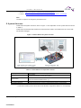
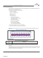
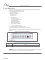
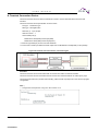
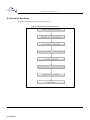
The following document contains information on Cypress products. 32-BIT MICROCONTROLLER FM3 Family Virtual Starter Kit USER MANUAL For the information for microcontroller supports, see the following web site. http://www.spansion.com/support/microcontrollers/ Publication Number FM3_MN706-00044 CONFIDENTIAL Revision 1.0 Issue Date July 18, 2014 U S E R 2 CONFIDENTIAL M A N U A L FM3_MN706-00044-1v0-E, July 18, 2014 U S E R M A N U A L Preface Thank you for your continued use of Spansion products. Please read this document, this product series 'Data Sheet' and 'FM3 family Peripheral manual' before using Virtual Starter Kit (VSK) package. This document purpose and target reader The document explains about VSK package function, behavior and how to use for engineers who develop products using this package. Note: This manual only explains about package/simulator function and behavior. This manual does not include the explanation about product series function and specification. You could refer to this product series 'Data Sheet' or 'FM3 family Peripheral manual' for series function and specification details. Trademark ARM and Cortex are the registered trademarks of ARM Limited in the EU and other countries. Microsoft, Windows are registered trademarks of Microsoft Corporation in the U.S. and other countries. QEMU is a trademark of Fabrice Bellard. OSCI, SystemC are trademarks or registered trademarks of Open SystemC Initiative, Inc. In the United States and other countries are used with permission. IAR Systems, IAR Embedded Workbench are trademarks or registered trademarks owned by IAR Systems AB. The company names and brand names herein are the trademarks or registered trademarks of their respective owners. Sample program and development environment Spansion offers sample programs free of charge for using the peripheral functions of the FM3 family. Spansion also makes available descriptions of the development environment required for this family. Feel free to use them to verify the operational specifications and usage of this Spansion microcontroller. Microcontroller support information http://www.spansion.com/Products/microcontrollers/32-bit-ARM-Core/fm3/Pages/overview_32fm3.aspx Note: The sample program is subject to be changed without notice. And the sample program's behavior and the way to use are only for standard case. Please make sure to test the sample program on your system before using the program. Our company does not have any responsibility for any problem happening on your side when you use this sample program. This document composition Virtual Starter Kit user manual consists of following chapter. CHAPTER1: Virtual Starter Kit CHAPTER2: Simulator Function Specification July 18, 2014, FM3_MN706-00044-1v0-E CONFIDENTIAL 3 U S E R M A N U A L CHAPTER3: External Device CHAPTER4: Run Simulation CHAPTER5: Simulation Data Analyzing Related manual The manuals related to VSK are listed below. See the manual appropriate to the applicable conditions. The contents of these manuals are subject to change without notice. Contact us to check the latest versions available. FM3 family peripheral manual Please refer to following document about each peripheral specification details of the product series supported by Virtual Starter Kit. FM3 Family PERIPHERAL MANUAL (Called "PERIPHERAL MANUAL" hereafter) FM3 Family PERIPHERAL MANUAL Timer Part (Called "Timer Part" hereafter) FM3 Family PERIPHERAL MANUAL Analog Macro Part (Called "Analog Macro Part" hereafter) FM3 Family PERIPHERAL MANUAL Communication Macro Part (Called "Communication Macro Part" hereafter) FM3 family peripheral manual (MCU SIMULATOR VERSION) Regard the list of peripherals of the MCU series supported by Virtual Starter Kit, there are differences in specification and behavior between simulator and real device. Please refer to the following document for these differences. FM3 Family PERIPHERAL MANUAL MCU SIMULATOR VERSION (Called "PERIPHERAL MANUAL MCU SIMULATOR VERSION" hereafter) FM3 Family PERIPHERAL MANUAL Timer Part MCU SIMULATOR VERSION (Called "Timer Part MCU SIMULATOR VERSION" hereafter) FM3 Family PERIPHERAL MANUAL Analog Macro Part MCU SIMULATOR VERSION (Called "Analog Macro Part MCU SIMULATOR VERSION" hereafter) FM3 Family PERIPHERAL MANUAL Communication Macro Part MCU SIMULATOR VERSION (Called "Communication Macro Part MCU SIMULATOR VERSION" hereafter) Data sheet Please refer to following document about details of device specification, electrical characteristics, external dimensions and order type. Microcontroller 32bit original FM3 family DATA SHEET Note: There are data sheet on each series. Please refer to the data sheet of the product series you use. 4 CONFIDENTIAL FM3_MN706-00044-1v0-E, July 18, 2014 U S E R M A N U A L Table of Contents CHAPTER1: Virtual Starter Kit ................................................................................................................ 9 1. Overview .................................................................................................................................. 10 2. System Structure ..................................................................................................................... 11 3. Included Files ........................................................................................................................... 12 CHAPTER2: Simulator Function Specification ...................................................................................... 13 1. Overview .................................................................................................................................. 14 2. Simulator Behavior................................................................................................................... 16 3. CPU ......................................................................................................................................... 19 4. Memory Map ............................................................................................................................ 20 5. Peripheral ................................................................................................................................ 21 6. External Device Model ............................................................................................................. 21 7. Debug Interface ....................................................................................................................... 23 8. Trace Function ......................................................................................................................... 24 8-1 I/O Trace Function....................................................................................................... 24 CHAPTER3: External Device ................................................................................................................ 25 1. Analog Input Device ................................................................................................................. 26 2. DIP Switch Device ................................................................................................................... 27 3. Tactile Switch Device ............................................................................................................... 28 4. Terminal Connection Device .................................................................................................... 29 5. Simulation Run Steps .............................................................................................................. 30 CHAPTER4: Run Simulation................................................................................................................. 31 1. Configurations of CPU Function .............................................................................................. 32 2. Configurations of Microcontroller Function ............................................................................... 33 3. Configurations of Device Function ........................................................................................... 34 3-1. Configurations of Analog Input Function .................................................................... 34 3-2. Configurations of DIP Switch Input Function .............................................................. 36 3-3. Configurations of Tactile Switch Input Function .......................................................... 38 3-4. Configurations of Terminal Connection Function ........................................................ 40 4. Configurations of Trace Function ............................................................................................. 42 4-1. Configurations of Trace Function ............................................................................... 42 4-2. Configurations for Selected Target Trace ................................................................... 43 5. How to Run Simulation ............................................................................................................ 44 6. How to Stop Simulation............................................................................................................ 45 CHAPTER5: Simulation Data Analyzing ............................................................................................... 47 1. Overview .................................................................................................................................. 48 2. Trace Type ............................................................................................................................... 49 3. Target Trace ............................................................................................................................ 50 4. Trace Result Visualization ....................................................................................................... 51 MAJOR CHANGES ............................................................................................................................... 52 July 18, 2014, FM3_MN706-00044-1v0-E CONFIDENTIAL 5 U S E R M A N U A L Figures Figure 1-1 Virtual Starter Kit system structure ........................................................................................... 11 Figure 2-1 FM3 Simulator phase and status ............................................................................................ 16 Figure 2-2 Run phase time chart .............................................................................................................. 17 Figure 2-3 FM3 Simulator Memory Map ................................................................................................... 20 Figure 2-4 Trace function ......................................................................................................................... 24 Figure 3-1 Analog input device GUI .......................................................................................................... 26 Figure 3-2 DIP switch GUI window ........................................................................................................... 27 Figure 3-3 Tactile switch device GUI window ........................................................................................... 28 Figure 3-4 Terminal connection device connection figure ......................................................................... 29 Figure 3-5 Simulation run steps flow chart ............................................................................................... 30 Figure 4-1 Simulator running window ....................................................................................................... 44 Figure 4-2 Stop Simulation ....................................................................................................................... 45 Figure 5-1 Example view of trace result at GTKWave .............................................................................. 51 6 CONFIDENTIAL FM3_MN706-00044-1v0-E, July 18, 2014 U S E R M A N U A L Tables Table 1-1 Virtual Starter Kit composition element ...................................................................................... 11 Table 2-1 Peripheral function supported in FM3 Simulator ....................................................................... 15 Table 2-2 Each time explanation .............................................................................................................. 17 Table 2-3 Connections between I/O Ports and External Devices ............................................................. 22 Table 3-1 Analog input device composition element ................................................................................. 26 Table 3-2 DIP switch composition element ............................................................................................... 27 Table 3-3 Tactile switch device composition element ............................................................................... 28 Table 4-1 Configuration list at CPU function ............................................................................................. 32 Table 4-2 Configuration list at microcontroller function ............................................................................. 33 Table 4-3 Analog input function option...................................................................................................... 34 Table 4-4 DIP switch function option ........................................................................................................ 36 Table 4-5 Tactile switch function option .................................................................................................... 38 Table 4-6 Terminal connection device function option .............................................................................. 40 Table 4-7 Trace function configurations .................................................................................................... 42 Table 4-8 Configuration option which select target trace .......................................................................... 43 Table 5-1 Items which are outputted in trace file at signal type ................................................................ 49 Table 5-2 Items which is outputted in trace file at transaction type ........................................................... 49 Table 5-3 Traceable I/O port list................................................................................................................ 50 July 18, 2014, FM3_MN706-00044-1v0-E CONFIDENTIAL 7 U S E R 8 CONFIDENTIAL M A N U A L FM3_MN706-00044-1v0-E, July 18, 2014 CHAPTER1: Virtual Starter Kit This chapter explains the functions of the Virtual Starter Kit. 1. Overview 2. System Structure 3. Included Files July 18, 2014, FM3_MN706-00044-1v0-E CONFIDENTIAL 9 U S E R M A N U A L 1. Overview Virtual Starter Kit is virtual evaluation environment which includes FM3 microcontroller and its external devices. FM3 microcontroller is provided by Spansion Inc (Spansion). The same with actual machine(board), it is possible to connect IDE debugger to Virtual Starter Kit. Virtual Starter Kit includes (1)hardware function simulator of FM3 microcontroller products (called “FM3 Simulator” hereafter) and (2)simulator of external devices (called “External Device Model” hereafter) which are controlled by FM3 microcontroller. The user can make these simulators operating together by simple instructions. With Virtual Starter Kit, the users can conduct software development, test and system evaluation without evaluation board. Package basic information − Package Name :Virtual Starter Kit − Package Version :1.00 − Package Type :Product Package Hardware requirements Microsoft Windows 7 version SP1 or later. Required softwares Visual C++2010 SP1 redistributable package − Software :Visual C++ 2010 SP1 redistributable package(x86) − Source :Microsoft Note: 1. Microsoft Visual C++ 2010 SP1 redistributable package(x86)is necessary for running application developed in Visual C++ 2010 SP1 when Visual C++ 2010 SP1 is not installed on the computer. 2. Microsoft Visual C++ 2010 SP1 redistributable package(x86)is available at Microsoft Corp. Download Center. Third party tool library Virtual Starter Kit includes Open Source Softwares(OSS). OSS are “libcoqemu.dll”, “libgcc_s_dw2-1.dll” and “libz-1.dll”. Please refer to the documents of OSS license in folder of “LICENSE”. QEMU − Software :qemu-0.12.5 − Source :Please contact us by e-mail. [email protected] − License :http://wiki.qemu.org/License Note: QEMU is provided under GPL license. It is included in Virtual Starter Kit as built DLL file. QEMU license include LGPL and BSD. SystemC & TLM2.0 − Software:systemc-2.2.0, TLM-2.0.1 10 CONFIDENTIAL FM3_MN706-00044-1v0-E, July 18, 2014 U S E R M A N U A L − Source :http://www.systemc.org/downloads/standards/systemc − License :http://www.systemc.org/about/policies/SystemC_Open_Source_License.pdf Note: The URL is subject to be changed by download source. 2. System Structure Virtual Starter Kit system structure is shown in Figure 1-1 and explanation of each system element is shown in Table 1-1. Virtual Starter Kit includes FM3 simulator and external device models. Virtual Starter Kit can connect with IDE Software Debugger. Figure 1-1 Virtual Starter Kit system structure Table 1-1 Virtual Starter Kit composition element Composition element Virtual Starter Kit FM3 Simulator Explanation This package. Included FM3 Simulator, External Device Model. Included FM3 microcontroller model which simulated Cortex-M3 CPU function and FM3 microcontroller hardware function. (*1) External Device Model External device model which connect to FM3 Simulator peripheral function. IDE Software Debugger Software debugger which connect to Virtual Starter Kit when run FM3 simulator. *1: FM3 Microcontroller product series which FM3 Simulator supported is different on each package. July 18, 2014, FM3_MN706-00044-1v0-E CONFIDENTIAL 11 U S E R M A N U A L 3. Included Files Virtual Starter Kit file structure is as follows. Spansion_VSK_MB9B510R | LIMITATION.txt │ RELEASENOTE.txt │ ├─LICENSE │ | LicenseAgreement.rtf │ | │ └─opensource │ BSD_license.txt │ LGPL_license.txt │ QEMU_license.txt │ SystemC_Open_Source_License.pdf │ ├─Manual … Folder of Manuals │ MN706-00044-1v0-E.pdf │ MN706-00045-1v0-E.pdf │ └─VirtualStarterKit … Folder of Virtual Starter Kit Files │ VirtualStarterKit.bat … Virtual Starter Kit Executable File │ ├─binary … Folder of FM3 Simulator Executable File │ ├─opensource … Folder of Open Source Software library Files │ └─plugin … Folder of Virtual Starter Kit’s plugin Files │ ├─configuration … Folder of Virtual Starter Kit’s configuration files and definition files │ │ cpu.ini … CPU Configuration File(Refer to sub section 51 for the details.) │ │ micom.ini … MCU Configuration File(Refer to sub section 52 for the details.) │ │ micom.xml … MCU Definition File │ │ svcd.ini │ │ trace.ini │ │ xsi.xml │ │ │ └─plugin … Folder of Virtual Starter Kit’s plugin configuration and defintion files │ analog_input.ini … Analog Input Congiguration File(Refer to sub section 3-1 for the details.) │ analog_input.xml … Analog Input Definition File │ dip_switch.ini … DIP Switch Configuration File(Refer to sub section 3-2 for the details.) │ tactile_switch.ini … Tactile Switch Configuration File(Refer to sub section 3-3 for the details.) │ switch.xml … Switch Device Definition File │ termif_server.ini … Terminal Connection Configuration File(Refer to sub section 3-4 for the details.) │ termif_server.xml … Terminal Connection Definition File │ XSIInit.ini … Init Device Configuration File │ XSIInit.xml … Init Device Definition File │ └─firmware … Folder of Firmware mb9bf51xr_pwmout.out 12 CONFIDENTIAL FM3_MN706-00044-1v0-E, July 18, 2014 CHAPTER2: Simulator Function Specification This chapter explains the Simulator functions specification. 1 : Overview 2 : Simulator Behavior 3 : CPU 4 : Memory Map 5 : Peripheral 6 : External Device Model 7 : Debug Interface 8 : Trace Function July 18, 2014, FM3_MN706-00044-1v0-E CONFIDENTIAL 13 U S E R M A N U A L 1. Overview FM3 Simulator is used to simulate hardware functions of FM3 microcontroller provided by Spansion. FM3 microcontroller is 32 bit general-purpose RISC microcontroller, whose CPU is CortexTM-M3 core of ARM Limited. In FM3 Simulator, QEMU is used as the Instruction set simulator of Cortex-M3. It allows users to conduct a software development with FM3 Simulator as the same with actual machine. Interface to connect microcontroller function I/O with External device model is also available in FM3 Simulator. It allows the users to run FM3 simulator with external devices connected. Simulator basic information Simulator Name :FM3 Simulator MB9B510R series Version :1.20 Target Series :MB9B510R series About FM3 Simulator supporting peripheral function FM3 Simulator supporting peripheral function is different according to FM3 Simulator objective lineup products and simulator version. Supported peripheral function is shown at Table 2-1. 14 CONFIDENTIAL FM3_MN706-00044-1v0-E, July 18, 2014 U S E R M A N U A L Table 2-1 Peripheral function supported in FM3 Simulator Peripheral function Basic peripheral Timer Analog macro Communicate macro description Clock available High rate CR timing available Clock monitoring function restriction of use *1 Reset available Low voltage detection available Low power consumption mode not available Interrupt available External interrupt・NMI control available DMAC available I/O port available CRC(Cycle Redundancy Check) available External bus interface restriction of use *2 Flash memory restriction of use *2 Watch dog timer available Dual timer available Watch counter prescaler available Watch counter available Real time clock not available Base timer I/O selector function available Base timer available Multifunction timer available PPG restriction of use *3 Quad counter restriction of use *4 12bit A/D converter available A/D timer trigger selector available 10bit D/A converter not available LCD controller not available Multifunction serial(UART) available Multifunction serial (CSIO) not available Multifunction serial (LIN) not available Multifunction serial (I2C) not available USB/Ethernetclock generate not available USB not available Ethernet not available CAN prescaler not available CAN controller not available HDMI-CEC/remote control receive not available *1: If the CSV function is enabled, the clock failure is detected when the main clock period or the sub clock period is 0ps. If the FCS function is enabled, the anomalous frequency is detected when the main clock period is 0ps. *2: External bus interface and Flash Memory register is not supported. It is replaced these area with RAM. *3: PPG does not support PPG IGBT mode. *4: Quad Counter does not support Quad Counter position rotation counter display function. Please refer to other document about peripheral function which you using lineup products. July 18, 2014, FM3_MN706-00044-1v0-E CONFIDENTIAL 15 U S E R M A N U A L 2. Simulator Behavior FM3 Simulator start simulation by booting FM3 Simulator main unit. FM3 Simulator behavior has 3 phases. − Initialization phase − Run phase (Reset state /Normal state /Debug state) − End phase FM3 Simulator phase and status is shown at Figure 2-1. Figure 2-1 FM3 Simulator phase and status 16 CONFIDENTIAL FM3_MN706-00044-1v0-E, July 18, 2014 U S E R M A N U A L Initialization phase At Initialization phase, CPU function configuration, microcontroller function configuration, setting of external connection interface and Device initialization are done. (CPU function configuration means to load image file which runs simulation) During FM3 Simulator's Initialization, simulation time keep zero, CPU function and microcontroller function do not run. External input signal from external connection interface can not received by FM3 Simulator. After FM3 Simulator initializing configuration finishes, FM3 Simulator automatically moves to Run phase. If software debugger connection configuration is enabled, FM3 Simulator will wait for connection notice from software debugger. After FM3 Simulator connects to software debugger, FM3 Simulator receives a register access from software debugger, then FM3 Simulator move to Run phase. Run phase Run phase has 3 states. − Reset state − Normal state − Debug state Run phase time chart is shown at Figure 2-2 and explaining on each time is shown at Table 2-2. Figure 2-2 Run phase time chart Table 2-2 Each time explanation Timing t0 t1 Explanation Simulation starting time Power on reset issuing time. t1 is issuedΔt time after t0. Power on reset release issuing time. t2 t2 is issued 1ps later after t1. Program starting time. Peripheral initial setting time to the register. t3 Between t3 and t2 interval is different depending on software program. July 18, 2014, FM3_MN706-00044-1v0-E CONFIDENTIAL 17 U S E R M A N U A L Reset state It is different between simulation start time and program start time because simulation starts after reset releases. Immediately after moving to Run phase, FM3 Simulator issues power-on reset, then do not run the program. Peripheral function does not run also, even external signal is input to FM3 Simulator. After 1ps from start simulation, power-on reset is released automatically. Then program starts and move to Run phase(Normal condition). Normal state Each peripheral function of FM3 microcontroller starts running after power-on reset is released, and then change to accessible condition from external interface. In the normal condition, if a system termination signal from simulator console or internal abnormality is detected, FM3 Simulator moves to End phase. Debug state In the run phase(Normal state), if application of software debugger comes to a break, simulator move to Run phase(Debug state). In the debug state simulation temporarily stops. In the debug status, CPU function and microcontroller function do not run, and simulation time doesn't change. If application of software debugger starts again, simulator moves back to Run phase(Normal state). End phase In the End phase, simulation is stops and simulation finishes. 18 CONFIDENTIAL FM3_MN706-00044-1v0-E, July 18, 2014 U S E R M A N U A L 3. CPU FM3 Simulator uses QEMU as Cortex-M3 CPU function. QEMU includes Cortex-M3 processer instruction set simulator, nested vectored interrupt controller(NVIC) and SysTick timer function. Please refer to web site below about QEMU details. http://wiki.qemu.org/ July 18, 2014, FM3_MN706-00044-1v0-E CONFIDENTIAL 19 U S E R M A N U A L 4. Memory Map FM3 Simulator Memory Map is shown at Figure 2-3. Figure 2-3 FM3 Simulator Memory Map Peripherals Area 0x41FF_FFFF Reserved 0x4006_9000 0x4006_7000 0x4006_6000 0xFFFF_FFFF Reserved 0xE010_0000 0xE000_0000 0x4006_4000 0x4006_3000 0x4006_2000 Cortex-M3 Private Peripherals 0x4006_1000 0x4006_0000 0x4005_0000 External Device Area 0x4004_0000 0x4003_F000 0x4003_C000 0x4003_B000 0x4003_A000 0x6000_0000 0x4003_9000 Reserved 0x4400_0000 0x4200_0000 0x4000_0000 0x2400_0000 0x2200_0000 0x200E_1000 0x200E_0000 0x200C_0000 0x2001_8000 0x2000_0000 0x1FFE_8000 32Mbytes Bit band alias Peripherals Reserved 32Mbytes Bit band alias Reserved 0x4003_6000 0x4003_5000 0x4003_4000 0x4003_3000 0x4003_2000 0x4003_1000 0x4003_0000 0x4002_F000 0x4002_E000 0x4002_9000 Flash I/F(Work) Flash(Work) 0x4002_8000 0x4002_7000 Reserved 0x4002_6000 0x4002_5000 SRAM1 SRAM0 0x4002_4000 0x4002_3000 Reserved 0x4002_2000 0x4002_1000 Flash(Work area)* Reserved Security/CR Trim* Flash(Main) 0x0000_0000 0x4003_8000 0x4003_7000 Ethernet-MAC1 Ethernet-Control-Reg. Ethernet-MAC0 CAN ch.1 CAN ch.0 Reserved DMAC USB ch.1 USB ch.0 EXT-bus I/F Reserved RTC Watch Counter CRC MFS CAN Prescaler USB Clock Ctrl LVD/DS mode HDMI-CEC GPIO Reserved Int-Req.Read EXTI Reserved CR Trim Reserved 0x4002_0000 D/AC A/DC QPRC Base Timer PPG Reserved MFT unit0 MFT unit0 MFT unit0 0x4001_6000 0x4001_5000 Dual Timer 0x4001_3000 0x4001_2000 0x4001_1000 0x4001_0000 Reserved Reserved SW WDT HW WDT Clock/Reset Reserved 0x4000_1000 0x4000_0000 Flash I/F(Main) FM3 Simulator has 4GB addressing memory area the same as actual machine. Maximum to 1 MB Flash Memory, maximum to 512 KB SRAM1 area, maximum to 512 KB SRAM0 area. 20 CONFIDENTIAL FM3_MN706-00044-1v0-E, July 18, 2014 U S E R M A N U A L FM3 Simulator has maximum memory size regardless of lineup products. 2 GB of 0x60000000-0xDFFFFFFF area as External bus area, you can connect External memory device to this memory area. Note: Not available on Virtual Starter Kit (version of 2014 March). Some of peripherals are not supported depending on product line up. We replace not supported peripheral area with RAM on FM3 Simulator. 5. Peripheral Please refer to 'FM3 Family PERIPHERAL MANUAL(MCU SIMULATOR VERSION)' about each peripheral details. 6. External Device Model Explain about External Device Model. FM3 Simulator can connect to External device model of respective external device. Details of Connections between FM3 Simulator’s I/O ports and External Device models are shown at Table 2-3. July 18, 2014, FM3_MN706-00044-1v0-E CONFIDENTIAL 21 U S E R M A N U A L Table 2-3 Connections between I/O Ports and External Devices Included Function Power Clock Reset External interrput・NMI control I/O port External bus interface A/D converter Base Timer Multifunction Serial IO Port External Device Model VCC - X0 - X0A - INITX - INT00-INT07 Tactile Switch INT08-INT15 - NMIX - P00-P07 DIP Switch P00-P0F - P10-P1F Tactile Switch P20-P2F - P30-P3F - P40-P4F - P50-P5F - P60-P6F - P70-P7F - P80-P8F - P90-P9F - PA0-PAF - PB0-PBF - PC0-PCF - PD0-PDF - PE0-PEF - PF0-PFF - EXT_master - ADTG0-ADTG2 - AN00 Analog Input AN01-AN15 - AVCC - AVRH - AVSS - TIOA0-TIOA7 - TIOB0-TIOB7 - SIN0 termif_server SOUT0 termif_server SIN1-SIN7 SOUT1-SOUT7 Multifunction Timer FRCK0-FRCK2 - IC00-IC03 - IC10-IC13 - IC20-IC23 - RTO00-RTO05 - RTO10-RTO15 - RTO20-RTO25 - Please refer to 'CHAPTER3:External Device' about External Device Model. 22 CONFIDENTIAL FM3_MN706-00044-1v0-E, July 18, 2014 U S E R M A N U A L 7. Debug Interface FM3 Simulator includes Debug interface to connect to software debugger which supports gdb port. Software debugger supporting gdb base connection can connect to FM3 Simulator. About software debugger which supports gdb port Following software debuggers can connect with FM3 Simulator. * Please refer to each tool bender website for latest support status. The following is the latest status in March 2014. IAR Embedded Workbench Software :IAR Embedded Workbench Source :IAR Systems Sourcery Code-Bench Software :Sourcery Code-Bench 2011.09.69 Source :Mentor Graphics Corporation July 18, 2014, FM3_MN706-00044-1v0-E CONFIDENTIAL 23 U S E R M A N U A L 8. Trace Function 8-1 I/O Trace Function Explain about I/O Trace function. FM3 Simulator also has I/O trace function to trace the value of a I/O signal. If you use Trace function you can analyze simulation data. Trace function schematic view is shown in Figure 2-4. Figure 2-4 Trace function Please refer to 'CHAPTER5:Simulation Data Analyzing' about trace function and simulation data analyze details. 24 CONFIDENTIAL FM3_MN706-00044-1v0-E, July 18, 2014 CHAPTER3: External Device This chapter explains the functions of the External Device. 1 : Analog Input Device 2 : DIP Switch Device 3 : Tactile Switch Device 4 : Terminal Connection Device July 18, 2014, FM3_MN706-00044-1v0-E CONFIDENTIAL 25 U S E R M A N U A L 1. Analog Input Device Analog input device is a GUI program which provides analog value to FM3 Simulator. Analog input device specification is shown below. Port type:Transaction type Data type:Analog value Direction(*1):Input Channel number:1 Connectable port:A/D Converter(ADC) analog input(ANxx) *1: Direction(Input/Output) is seen from FM3 Simulator Analog input device GUI is shown at Figure 3-1 and composition element explanation is shown at Table 3-1. Figure 3-1 Analog input device GUI Minimum Value Slider Maximum Value Current Value Table 3-1 Analog input device composition element Composition Explanation element Minimum Value Maximum Value Current Value Slider This textbox is showed minimum value and setting minimum value is available. (Default value is 0). This textbox is showed maximum value and setting maximum value is available. (Default value is 5). This textbox is showed the analog input value and setting the analog input value is available. (Default is Minimum Value). This slider is showed the position of analog input value. Changing the analog input value is available by the bar slide. (Default is Minimum Value). Function Setting the analog input value is available by the bar slide. The value unit is Volt. Also, setting the analog input value is available by set a value to 'Value' textbox. The value range of analog input bar can be changed by modifying the Min's and Max's value. Enter a value number to 'Min' textbox to change Min value, enter a value number to 'Max' textbox to change Max value. Maximum value must be bigger than Minimum value. The characters which are not numeric character can not be accepted. In this case, error message is displayed. 26 CONFIDENTIAL FM3_MN706-00044-1v0-E, July 18, 2014 U S E R M A N U A L 2. DIP Switch Device DIP switch device is a GUI program which is used to input digital value. The GUI includes 8 switches, each switch is used to input digital value for 1 bit. DIP switch device specification is shown below. Port type:Signal type Data type:1bit digital value Direction(*1):Input Channel number:8 Connectable port(*2): General I/O port input(Pxx) Timer trigger input(TIOAx, TIOBx) Input capture input(ICx) External interrupt input(INTxx) External reset input(INITX) Non-maskable interrupt(NMIX) A/D converter trigger input(ADTGx) *1: Direction (Input/Output) is seen from FM3 Simulator *2: Connected to general I/O port P00-P07 in this package. DIP switch device GUI window is shown at Figure 3-2 and composition element explanation is shown at Table 3-2. Figure 3-2 DIP switch GUI window Table 3-2 DIP switch composition element Composition Explanation element Switch lever 1bit digital value input lever (Default is OFF). Function Move up the switch lever to switch ON. Move down the switch lever to switch OFF. The switch status is kept until the switch lever moves up or down again. When switch is ON, input value to FM3 Simulator is 1, when switch is OFF, input value to FM3 Simulator is 0. July 18, 2014, FM3_MN706-00044-1v0-E CONFIDENTIAL 27 U S E R M A N U A L 3. Tactile Switch Device Tactile switch device is a GUI program which is used to input digital value. The GUI includes 8 switches, each switch is used to input digital value for 1 bit. Tactile switch device specification is shown below. Port type:Signal type Data type:1bit digital value Direction(*1):Input Channel number:8 Connectable port(*2): General I/O port input(Pxx) Timer trigger input(TIOAx, TIOBx) Input capture input(ICx) External interrupt input(INTxx) External reset input(INITX) Non-maskable interrupt(NMIX) A/D converter trigger input(ADTGx) *1: Direction (Input/Output) is seen from FM3 Simulator. *2: Connected to External interrupt input INT00-INT07 in this package. Tactile switch device GUI window is shown at Figure 3-3 and composition element explanation is shown at Table 3-3. Figure 3-3 Tactile switch device GUI window Table 3-3 Tactile switch device composition element Composition element Button Explanation 1bit digital value input lever (Default is OFF). Function Move up the switch lever to switch ON. Move down the switch lever to switch OFF. When switch is ON, input value to FM3 Simulator is 1, when switch is OFF, input value to FM3 Simulator is 0. 28 CONFIDENTIAL FM3_MN706-00044-1v0-E, July 18, 2014 U S E R M A N U A L 4. Terminal Connection Device Terminal connection device is device model which is used to connect FM3 Simulator with a terminal emulator. Terminal connection device specification is shown below. Port type:Transaction type Data type:8bit digital value Direction(*1):Input, Output Channel number:1 Connectable port(*2): Multifunction serial(UART) serial input(SINx) Multifunction serial(UART) serial output(SOTx) *1: Direction (Input/Output) is seen from FM3 Simulator *2: Connected to serial input SIN0 and serial output SOT0 at Multifunction serial(UART) in this package. Figure 3-4 Terminal connection device connection figure Function Terminal connection device sends data which is received from UART to terminal emulator. Terminal connection devices send data which is received from terminal emulator to UART byte by byte. Terminal program behavior (Linefeed code handling, Data transmit unit) depends on the Terminal program configuration. Note: 1. Configuration example when using Tera Term Version 4.73. July 18, 2014, FM3_MN706-00044-1v0-E CONFIDENTIAL 29 U S E R M A N U A L 5. Simulation Run Steps Simulation run steps flow chart is shown at Figure 3-5. Figure 3-5 Simulation run steps flow chart 30 CONFIDENTIAL FM3_MN706-00044-1v0-E, July 18, 2014 CHAPTER4: Run Simulation This chapter explains the functions of the Run Simulation. 1. 1. Configurations of CPU Function 2. Configurations of Microcontroller Function 3. Configurations of Device Function 4. Configurations of Trace Function 5. How to Run Simulation July 18, 2014, FM3_MN706-00044-1v0-E CONFIDENTIAL 31 U S E R M A N U A L 1. Configurations of CPU Function The CPU function is configured by using CPU configuration file (cpu.ini). Configurations are shown at Table 4-1. Table 4-1 Configuration list at CPU function Option Entry name Target image file configuration ELF_FILE Software debugger configuration GDB_STUB_PORT Explanation Configuration of file path of FM3 Simulator's image file. Configuration of Software debugger connection. Target image file configuration Configuration of file path of FM3 Simulator's image file is shown below. Syntax [GENERAL] ELF_FILE=TargetImageFilePath Section GENERAL EntryName ELF_FILE Value TargetImageFilePath Type:String(Default value:Sample image including simulator) Remarks Please assign ELF format file to this option. This configuration cannot skip. Example ELF_FILE= Sample image including simulator Software debugger configuration Configuration of GdbStb port number, which is used in connection with software debugger, is shown below. Syntax [GENERAL] GDB_STUB_PORT=GdbStubPort Section GENERAL EntryName GDB_STUB_PORT 32 CONFIDENTIAL FM3_MN706-00044-1v0-E, July 18, 2014 U S E R M A N U A L Value GdbStubPort Type:Int(Default value:1234) Remarks If this option is disabled, software debugger is not connected. This option is disabled in default. Example GDB_STUB_PORT=1234 2. Configurations of Microcontroller Function The MCU function is configured by using MCU configuration file (micom.ini). Configurations are shown at Table 4-2. Table 4-2 Configuration list at microcontroller function Option PLL period configuration Entry name PLL_CLK_PERIOD Explanation Configuration of PLL clock period. PLL clock period configuration PLL clock period configuration is shown below. Syntax [GENERAL] PLL_CLK_PERIOD=PllClockPeriod Section GENERAL EntryName PLL_CLK_PERIOD Value PllClockPeriod Type:double(Default value:6944.4(ps)… Correspond to 144MHz) Remarks Please configure the value as 'ps' scale. Example PLL_CLK_PERIOD=6944.4 July 18, 2014, FM3_MN706-00044-1v0-E CONFIDENTIAL 33 U S E R M A N U A L 3. Configurations of Device Function 3-1. Configurations of Analog Input Function Analog input function is configured by using analog input configuration file (analog_input.ini). Configurations are shown at Table 4-3. Table 4-3 Analog input function option Option Entry name Explanation Period of synchronization, between Period of synchronization SYNC_PERIOD FM3 Simulator and Analog input device. Unit of synchronization period, Unit of synchronization period TIME_UNIT between FM3 Simulator and Analog input device. Period of synchronization Configuration of synchronization period, between FM3 Simulator and Analog input device, is shown below. Syntax [GENERAL] SYNC_PERIOD=Value Section GENERAL EntryName SYNC_PERIOD Value Value Type:unsigned int(Default value:1ms) Remarks If the period value which is smaller than configured CPU clock period, there is a possiblity that FM3 simulator can drop any analog input data. Therefore, please configure the period value bigger than CPU clock. Please refer 'TIME_UNIT' about the unit. Example SYNC_PERIOD=1 Unit of synchronization period Configuration of synchronization period unit, between FM3 Simulator and Analog input device, is shown below. Syntax [GENERAL] TIME_UNIT=unit Section GENERAL EntryName TIME_UNIT 34 CONFIDENTIAL FM3_MN706-00044-1v0-E, July 18, 2014 U S E R M A N U A L Value unit Type:string(Default value:ms) Remarks If the period which smaller than CPU clock is configured, you have risk of lost input value from analog input GUI. Therefore, please configure the period which bigger than CPU clock. Please refer 'SYNC_PERIOD' about the period value. Example TIME_UNIT=ms July 18, 2014, FM3_MN706-00044-1v0-E CONFIDENTIAL 35 U S E R M A N U A L 3-2. Configurations of DIP Switch Input Function DIP switch input function is configured by using DIP switch input configuration file (dip_switch.ini). Configurations are shown at Table 4-4. Table 4-4 DIP switch function option Option Entry name Explanation Period of synchronization, between Period of synchronization SYNC_PERIOD FM3 Simulator and DIP switch input device. Unit of synchronization period, Unit of synchronization period TIME_UNIT between FM3 Simulator and DIP switch input device. Period of synchronization Configuration of synchronization period, between FM3 Simulator and DIP switch input device, is shown below. Syntax [GENERAL] SYNC_PERIOD=Value Section GENERAL EntryName SYNC_PERIOD Value Value Type:int(Default value:1) Remarks If the period value which is smaller than configured CPU clock period, there is a possiblity that FM3 simulator can drop any input data from DIP Switch. Therefore, please configure the period value bigger than CPU clock. Please refer 'TIME_UNIT' about the unit. Example SYNC_PERIOD=1 Unit of synchronization period Configuration of synchronization period unit, between FM3 Simulator and DIP switch input device, is shown below. Syntax [GENERAL] TIME_UNIT=unit Section GENERAL EntryName TIME_UNIT 36 CONFIDENTIAL FM3_MN706-00044-1v0-E, July 18, 2014 U S E R M A N U A L Value unit Type:string(Default value:ms) Remarks If the period value which is smaller than configured CPU clock period, there is a possiblity that FM3 simulator can drop any input data from DIP Switch. Therefore, please configure the period value bigger than CPU clock. Please refer 'SYNC_PERIOD' about the period value. Example TIME_UNIT=ms July 18, 2014, FM3_MN706-00044-1v0-E CONFIDENTIAL 37 U S E R M A N U A L 3-3. Configurations of Tactile Switch Input Function Tactile switch input function is configured by using Tactile switch input configuration file (tactile_switch.in). Configurations are shown at Table 4-5. Table 4-5 Tactile switch function option Option Entry name Explanation Period of synchronization, between Period of synchronization SYNC_PERIOD FM3 Simulator and Tactile switch input device. Unit of synchronization period, Unit of synchronization period TIME_UNIT between FM3 Simulator and Tactile switch input device. Period of synchronization Configuration of synchronization period, between FM3 Simulator and Tactile switch input device, is shown below. Syntax [GENERAL] SYNC_PERIOD=Value Section GENERAL EntryName SYNC_PERIOD Value Value Type:int(Default value:1) Remarks If the period value which is smaller than configured CPU clock period, there is a possiblity that FM3 simulator can drop any input data from Tactile Switch. Therefore, please configure the period value bigger than CPU clock. Please refer 'TIME_UNIT' about the unit. Example SYNC_PERIOD=1 Unit of synchronization period Configuration of synchronization period unit, between FM3 Simulator and Tactile switch input device, is shown below. Syntax [GENERAL] TIME_UNIT=unit Section GENERAL EntryName TIME_UNIT 38 CONFIDENTIAL FM3_MN706-00044-1v0-E, July 18, 2014 U S E R M A N U A L Value unit Type:string(Default value:ms) Remarks If the period value which is smaller than configured CPU clock period, there is a possibility that FM3 simulator can drop any input data from Tactile Switch. Therefore, please configure the period value bigger than CPU clock. Please refer 'SYNC_PERIOD' about the period value. Example TIME_UNIT=ms July 18, 2014, FM3_MN706-00044-1v0-E CONFIDENTIAL 39 U S E R M A N U A L 3-4. Configurations of Terminal Connection Function Terminal connection function is configured by using terminal connection configuration file (termif_server.ini). Configurations are shown at Table 4-6. Table 4-6 Terminal connection device function option Option Entry name Debug mode DEBUG Host name HOST Port number PORT Connection configuration CONNECT Explanation Configuration of debug mode for Terminal connection device. Configuration of Host name for Terminal connection device. Configuration of Port number for terminal connection device. Configuration of connection (Disable/Enable) for Terminal connection device. Debug mode Configuration of debug mode for Terminal connection device is shown below. Syntax [GENERAL] DEBUG=DebugMode Section GENERAL EntryName DEBUG Value DebugMode Type:int(Default value:0) 0:Disenable 1:Enable(Debug message is shown under simulation running.) Remarks Example DEBUG=0 Host name Configuration of Host name for Terminal connection device is shown below. Syntax [NETWORK] HOST= HostName Section NETWORK EntryName HOST 40 CONFIDENTIAL FM3_MN706-00044-1v0-E, July 18, 2014 U S E R M A N U A L Value HostName Type:String(Default value:localhost) Remarks This configuration used for port connection with Terminal bridge. Example HOST=localhost Port number Configuration of Port number for terminal connection device is shown below. Syntax [NETWORK] PORT=PortNumber Section NETWORK EntryName PORT Value PortNumber Type:int(Default value:1204) Remarks This configuration used for port connection with Terminal bridge. Example PORT=1204 Connection configuration Configuration of connection(Disable/Enable) for Terminal connection device is shown below. Syntax [NETWORK] CONNECT=Connect Section NETWORK EntryName CONNECT Value Connect Type:int(Default value:0) 0:Disable(Terminal program unconnected) 1:Enable(Terminal program connected) Remarks This configuration used for port connection with Terminal bridge. Terminal connection bridge program is to be booted before boot the simulator when this configuration configure to 1. Please configure 0 to this configuration when Terminal program does not connect. Example Connect=1 July 18, 2014, FM3_MN706-00044-1v0-E CONFIDENTIAL 41 U S E R M A N U A L 4. Configurations of Trace Function 4-1. Configurations of Trace Function Trace function is configured by using Trace configuration file (svcd.ini). Configurations are shown at Table 4-7. Table 4-7 Trace function configurations Option Entry name Trace file name VCD_FILE Simulation unit time TIME_UNIT Explanation Configuration of Trace file name(.vcd) including file path. Configuration of simulation minimum unit time. Trace file name Configuration of Trace file name(.vcd), possible to add the file path, is shown below. Syntax [GENERAL] VCD_FILE=file Section GENERAL EntryName VCD_FILE Value file Type:String(Default value:..¥svcd.vcd) Remarks IF VCD_FILE setting is default value, the svcd.vcd is created in the VirtualStarterKit folder. Example VCD_FILE= svcd.vcd Simulation minimum unit time Configuration of simulation minimum unit time is shown below. Syntax [GENERAL] TIME_UNIT=Value Section GENERAL EntryName TIME_UNIT Value Value Type:int(Default value:ps) Remarks Example TIME_UNIT=ps 42 CONFIDENTIAL FM3_MN706-00044-1v0-E, July 18, 2014 U S E R M A N U A L 4-2. Configurations for Selected Target Trace Configurations for selected target trace are configured by using Trace select configuration file (trace.ini). Configurations are shown at Table 4-8. Table 4-8 Configuration option which select target trace Option Entry name Explanation Target trace signal name is Trace ON/OFF TracePortName configured as EntryName and ON/OFF is configured as the Value. Trace ON/OFF Target trace signal name is configured as EntryName and ON/OFF is configured Value. The example is shown below. Syntax [GENERAL] TracePortName=ON/OFF Section GENERAL EntryName TracePortName Type:String(Target trace signal name) Value on/off Type:String(Default value:OFF) Remarks Example [GENERAL] P00=ON SOT1=OFF Selectable port as TracePortName is shown at 'Table 5-3 Traceable I/O port list' at 'CHAPTER5: Simulation Data Analyzing'. July 18, 2014, FM3_MN706-00044-1v0-E CONFIDENTIAL 43 U S E R M A N U A L 5. How to Run Simulation To run the simulation, execute the batch file VirtualStarterKit.bat. If the simulation runs properly, the simulator will wait to connect a Terminal Program as shown in Figure 4-1. Connect a Terminal Program to the Terminal Connection Device of the simulator. Refer to sub section 3-4 for the Terminal Connection setting. Figure 4-1 Simulator running window 44 CONFIDENTIAL FM3_MN706-00044-1v0-E, July 18, 2014 U S E R M A N U A L 6. How to Stop Simulation To stop the simulation, click an “x” button on the Simulator running window. If the Debugger connects to simulator, please disconnect it before stop simulation. Figure 4-2 Stop Simulation To stop the simulation, click an “x” button on the Simulator running window. July 18, 2014, FM3_MN706-00044-1v0-E CONFIDENTIAL 45 U S E R 46 CONFIDENTIAL M A N U A L FM3_MN706-00044-1v0-E, July 18, 2014 CHAPTER5: Simulation Data Analyzing This chapter explains the functions of the Simulation Data Analyzing. 1. Overview 2. Trace Type 3. Target Trace 4. Trace Result Visualization July 18, 2014, FM3_MN706-00044-1v0-E CONFIDENTIAL 47 U S E R M A N U A L 1. Overview FM3 Simulator has I/O trace function to trace the value of a I/O signal. Trace function option configuration is necessary for I/O trace function before the simulation run. (See also '4-5. Option configuration of Trace function') VCD format trace file is output to a trace file after simulation run finishes when any signal becomes a target to be traced. If you use Trace function you can analyze simulation data. 48 CONFIDENTIAL FM3_MN706-00044-1v0-E, July 18, 2014 U S E R M A N U A L 2. Trace Type Trace function is divided into two types, depending on target trace port data type. Two types are shown below. − Signal type − Transaction type Signal type Signal type port is used for port of signal level. In case of selecting signal type port as target trace, items which is outputted in trace file(.vcd) are shown at Table 5-1. Table 5-1 Items which are outputted in trace file at signal type Items Explanation ContentID Data type ID of selected port as target trace. Data Communication data of selected port as target trace. Transaction type Transaction type port is used for port including multiple signals in one-transaction. In case of selecting transaction type port as target trace, items which is outputted in trace file(.vcd) are shown at Table 5-2. Table 5-2 Items which is outputted in trace file at transaction type Items Explanation ContentID Data type ID which selected as trace target port conducting. Mode Communication mode of selected port as target trace. (*1) Command Transaction handling which write/read to communication data. (WRITE, READ) Address Transaction destination address (*2). Length Communication data length (byte). Data Communication data of selected port as target trace. Response Transaction response status. *1: Items which are outputted only Multifunction serial. *2: Items which are outputted only External Bus Interface. July 18, 2014, FM3_MN706-00044-1v0-E CONFIDENTIAL 49 U S E R M A N U A L 3. Target Trace Traceable I/O port list on FM3 Simulator is shown at Table 5-3. Table 5-3 Traceable I/O port list Including Function Power Clock Reset External interrput・NMI control I/O port External bus interface A/D converter Base Timer Multifunction Timer 50 CONFIDENTIAL Tracetype VCC Signal X0 Signal X0A Signal INITX Signal INT00-INT07 Signal INT08-INT15 Signal NMIX Signal P00-P07 Signal P00-P0F Signal P10-P1F Signal P20-P2F Signal P30-P3F Signal P40-P4F Signal P50-P5F Signal P60-P6F Signal P70-P7F Signal P80-P8F Signal P90-P9F Signal PA0-PAF Signal PB0-PBF Signal PC0-PCF Signal PD0-PDF Signal PE0-PEF Signal PF0-PFF Signal EXT_master Transaction ADTG0-ADTG2 Signal AN00 Signal AN01-AN15 Signal AVCC Signal AVRH Signal AVSS Signal TIOA0-TIOA7 Signal TIOB0-TIOB7 Signal FRCK0-FRCK2 Signal IC00-IC03 Signal IC10-IC13 Signal IC20-IC23 Signal RTO00-RTO05 Signal RTO10-RTO15 Signal RTO20-RTO25 Signal FM3_MN706-00044-1v0-E, July 18, 2014 U S E R M A N U A L 4. Trace Result Visualization Trace result is output to trace file under VCD format. The user can visualize trace result, by using a waveform view supporting VCD format file. Wave form viewer Tool:GTKWave Source:http://gtkwave.sourceforge.net/ The wave form viewer can conduct VCD format file. The viewer is free of charge. Example view of trace result at GTKWave is shown at Figure 5-1. Figure 5-1 Example view of trace result at GTKWave Note: 1. ContentID, Mode, Command and Response are outputted trace file with ASCII code. 2. You can check the trace result as character, if you display data format change to ASCII on the viewer, when the trace result is displayed on the waveform viewer. July 18, 2014, FM3_MN706-00044-1v0-E CONFIDENTIAL 51 U S E R M A N U A L MAJOR CHANGES Page Section Changes Revision 1.0 - 52 CONFIDENTIAL - Initial release FM3_MN706-00044-1v0-E, July 18, 2014 U S E R July 18, 2014, FM3_MN706-00044-1v0-E CONFIDENTIAL M A N U A L 53 U S E R 54 CONFIDENTIAL M A N U A L FM3_MN706-00044-1v0-E, July 18, 2014 U S E R M A N U A L MN706-00044-1v0-E Spansion・Controller Manual FM3 Family 32-BIT MICROCONTROLLER Virtual Starter Kit User Manual July 2014 Rev. 1.0 Published:Spansion Inc. Edited:Communications Dept. July 18, 2014, FM3_MN706-00044-1v0-E CONFIDENTIAL 55 U S E R M A N U A L Colophon The products described in this document are designed, developed and manufactured as contemplated for general use, including without limitation, ordinary industrial use, general office use, personal use, and household use, but are not designed, developed and manufactured as contemplated (1) for any use that includes fatal risks or dangers that, unless extremely high safety is secured, could have a serious effect to the public, and could lead directly to death, personal injury, severe physical damage or other loss (i.e., nuclear reaction control in nuclear facility, aircraft flight control, air traffic control, mass transport control, medical life support system, missile launch control in weapon system), or (2) for any use where chance of failure is intolerable (i.e., submersible repeater and artificial satellite). Please note that Spansion will not be liable to you and/or any third party for any claims or damages arising in connection with above-mentioned uses of the products. Any semiconductor devices have an inherent chance of failure. You must protect against injury, damage or loss from such failures by incorporating safety design measures into your facility and equipment such as redundancy, fire protection, and prevention of over-current levels and other abnormal operating conditions. If any products described in this document represent goods or technologies subject to certain restrictions on export under the Foreign Exchange and Foreign Trade Law of Japan, the US Export Administration Regulations or the applicable laws of any other country, the prior authorization by the respective government entity will be required for export of those products. Trademarks and Notice The contents of this document are subject to change without notice. This document may contain information on a Spansion product under development by Spansion. Spansion reserves the right to change or discontinue work on any product without notice. The information in this document is provided as is without warranty or guarantee of any kind as to its accuracy, completeness, operability, fitness for particular purpose, merchantability, non-infringement of third-party rights, or any other warranty, express, implied, or statutory. Spansion assumes no liability for any damages of any kind arising out of the use of the information in this document. ® ® ® TM TM Copyright © 2014 Spansion. All rights reserved. Spansion , the Spansion logo, MirrorBit , MirrorBit Eclipse , ORNAND , TM TM Easy DesignSim , Traveo and combinations thereof, are trademarks and registered trademarks of Spansion LLC in the United States and other countries. Other names used are for informational purposes only and may be trademarks of their respective owners. 56 CONFIDENTIAL FM3_MN706-00044-1v0-E, July 18, 2014