1
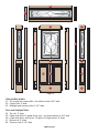
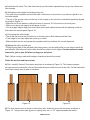
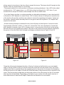
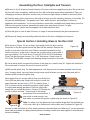
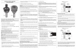
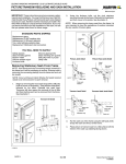
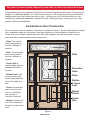
Entry Door Construction Made Simple with Freud’s Entry & Interior Door Router Bit System
Congratulations on your purchase of Freud’s Entry & Interior Door Router Bit System. This unique set
allows you to build high quality 1-3/4” thick exterior doors or 1-3/8” thick interior doors, plus beautiful
sidelights and transoms in almost any size or style. In this poster, you’ll find information on: door
construction; planning & preparation; materials & safety; milling your parts; routing your rails, stiles,
profiles & joints; and installation.
Introduction to Door Construction
Door units may consist of a number of elements. As shown in Figure 1, the unit will include the hinged
door, sometimes called the “door panel,” and may include one or two sidelights to flank the door.
Some units also include a transom above the door and sidelights. Here are some other common
terms that will be used throughout these instructions:
- Stiles: The vertical
frame components of
the door, sidelight or
transom.
- Rails: The horizontal
frame components of
the door, sidelight or
transom.
Rails
- Center Stile: A
vertical divider located
between the stiles of
the door.
Decorative
Glass
- Raised Panel: A flat
wooden section with
routed edges fitted into
slots in the stiles and
rails.
Stiles
Mortise
& Tenon
Joint
- Tenon: An extended
piece of wood on the
end of a rail that fits
into a pocket, or
“mortise” in the stile.
Raised
Panels
Center
Stile
- Mortise: A pocket cut
in a stile that matches
the tenon on the end of
a rail.
Figure 1
Page 1 of 17
Materials Required
In addition to the Freud Entry & Interior Door router bits, you will need the following tools and supplies
to build your door unit:
- Raised Panel Router Bit for profiling wooden raised panels.
- Variable speed router, 2-1/ 4 HP minimum, 3-1/4 HP preferred.
- Router table with fence, miter gauge and two or more featherboards. We also strongly recommend
that a shop vacuum or dust collector be used with the router table.
- Table saw for ripping stiles and rails.
- Infeed and outfeed stock supports such as roller stands or similar devices to support long boards
- Mortising machine, Drill Press with mortising attachment, or Drill Press with brad point bits.
- Various common woodworking hand tools including hammer, chisels, rule, straight edge, square,
coping saw.
- Clamps with the capacity to secure all door joints.
- A sturdy, level work table or saw horses for door assembly.
- Lumber for door parts (and door jamb, if required).
- Exterior wood glue.
- Glass for door, sidelights and transom, if needed.
- Sealant or glazing tape for glass installation, if needed.
A list of suggested sources for many materials used in making doors such as glue, glass and
thresholds will be found at www.freudtools.com.
Safety Tips
Creating your own entry or passage door is a fun and rewarding woodworking project that enables
you to add curb appeal or distinction to any door of your home. As with any woodworking project,
however, your first concern must always be safety. To get the best performance and results from your
Freud cutting tools, observe these safety recommendations for EACH operation:
- Make sure that you are well rested before working with power equipment.
- Do not use power equipment if you have consumed any drugs or alcohol. If you are taking
prescription medication, check with your physician to ensure it is safe for you to operate power
equipment.
- Never use a router bit that is damaged or dull.
- Always turn off and unplug the router before removing, installing or adjusting bits, adjusting the
router or fence, or assembling or disassembling bits.
! WARNING: Failure to obey these warnings could lead to serious bodily injury or death:
- Use router bits with a router only.
- Carbide is a very hard and brittle material. Slight shocks can damage the carbide. Before each
use, check that the bit is sharp and free from damage. DO NOT use the bit if it is dull, broken,
cracked or if any damage is noticed or suspected.
- Before each use, make sure that at least 80% of the router bit shank is inserted into the collet. The
end of the bit shank should be at least 1/8” from the bottom of the collet.
- Before each use, ensure that the collet has been tightened and that the work piece is secure.
- Read and obey all warnings and instructions contained in the router’s user’s manual, and for any
accessory that is used. If you do not have the correct user’s manual, obtain one from the
manufacturer before using the router bit.
Page 2 of 17
- Always wear eye protection or a full face shield complying with current ANSI Standard Z87.1
- Keep body, clothing and hair clear of spinning bit. Do not wear loose hanging clothing or jewelry.
- Use a router table and fence wherever possible. Be sure all guards are in place.
- Bits over 1-1/2” in diameter must only be used with the router mounted in the table.
- Use multiple passes when removing large quantities of material.
- Never use bit on router that will exceed maximum recommended RPM of bit.
- If you have any questions regarding your router bits, please call Freud Customer Service at 800472-7307. In Canada call 800-263-7016.
- Before making any structural alterations to your home, consult a licensed general contractor,
licensed architect or professional engineer.
- Be sure to consult your local building authority before proceeding with your door project.
- Keep these instructions in a safe place for future reference.
Planning and Preparation
a) Contact your local building department to ask about local codes for door construction and
installation. The instructions that follow are only intended to illustrate the steps involved in door
construction. Your local building codes may have special requirements, particularly in areas that are
prone to severe weather. Be sure to obey all local building codes. Note: Product Has Not Undergone
DP Rating Procedures.
b) Plan the project carefully before purchasing materials. Refer to the reference below for formulas to
calculate the widths and lengths of your stiles, rails, panels and glass inserts. If this is your first door
construction project, or if you are building a complex unit with sidelights or a transom, you may find it
helpful to draw out the stiles, rails and other elements full size to serve as a construction blueprint.
This will serve as a handy reference for calculating and double-checking the sizes of all parts of the
project.
Note: If the project requires that you build a new door jamb, be sure to allow for the thickness of the
jamb elements as you calculate your door and sidelight dimensions. Refer to Special Section 2 for
more information on door jamb construction and installation.
c) Be sure to obtain enough stock to build the complete door unit, plus extra stock for making test
cuts. This will make it easier to match the grain and color of the material for a more attractive finish,
and milling all stock to thickness at the same time avoids inconsistencies that can affect the quality of
your joints.
d) Choose stock with care! Lumber for door construction must be perfectly straight, and free from
defects such as knots, splits and checks.
Calculating Sizes of Door Parts
Stock thickness: 1-3/4” for exterior doors, sidelights and transoms. 1-3/8” for interior doors.
Note: We recommend the following widths, but if you already have decorative glass for your door
unit, or if you plan to use stock sizes of decorative glass, check the size of the glass before
proceeding. You may need to adjust the stile and rail sizes below to accommodate your glass.
Page 3 of 17
8
3
4
1
4
3
9
6
6
2
9
7
7
Figure 2
Stile and Rail widths:
#1 - Full length door panel stiles: Use stiles at least 4-3/4” wide.
#2 - Center stile: 4” wide.
#3 - Sidelight and transom stiles: 2-1/2” wide.
Door and Sidelight Rails:
#4 - Top rail: 5” wide.
#5 - Upper mid rail (for 6-panel doors only - not shown above): 3-3/4” wide.
#6 - Lower mid rail (or mid rail for 1/2 light or 3/4 light doors): 6” wide.
#7 - Bottom rail: 9” wide.
#8 - Transom rails: 2-1/2” wide.
Page 4 of 17
Stile lengths: Should be equal to the finished height of the door, sidelight or transom.
Note: Length of center stiles with stub tenons = distance between rails + 1”
Rail lengths: are determined based on the width of the stiles and the length of the tenon you plan to
use:
Rails with stub tenons: For many joints in your door, as well as any stile and rail joints in sidelights
and transoms, you can use the rail bit as it was supplied from factory. This produces a 1/2” long “stub”
tenon as shown in Figure 3. Here is a formula for calculating the length of rails with these stub
tenons:
Rail length = door, sidelight or transom width – (stile width x 2) + 1”
Example: for a 36” wide door with 4-3/4” wide stiles, the calculation is: 36" – 4-3/4” – 4-3/4” + 1" = 27-1/2”
Figure 3
®
1/2" Long Stub Tenon
Rails with extended tenons: Joints that form the top and bottom corners of the door panel are
subject to more stress, so you should use longer tenons, as shown in Figure 4. You also may wish to
use a longer tenon for joints between the middle rail and the stiles for extra strength. The procedure
for milling longer tenons will be described in the section to follow. For these high-stress joints of 3’0”
wide doors, Freud recommends tenons of at least 2-1/2” length. For 2’8” wide or narrower doors, use
at least 2” long tenons. Here are formulas for calculating rail length including these tenons:
Rails with 2-1/2” Tenons: Rail = door width – (stile width X 2) + 5”
Example: for a 36” wide door with 4-3/4” wide stiles, the calculation is: 36" – 4-3/4" – 4-3/4" + 5" = 31-1/2”
®
Figure 4
2-1/2" Long Extended Tenon
Rails with 2” Tenons: Rail = door width – (stile width X 2) + 4”
Example: for a 32” wide door with 4-3/4” wide stiles, the calculation is: 32" – 4-3/4" – 4-3/4" + 4" = 26-1/2”
Page 5 of 17
Wooden Panels (#9): Allow for expansion of the panels as humidity changes. Panels will expand
more across their width (across the grain) than they will along their length (with the grain). Calculate
Panel sizes as follows:
Width = distance between stiles + 3/4”. (allows 1/8” on each side for expansion)
Width Of Panel
1/8"
Figure 5
STILE
1/8"
STILE
1/2"
1/2"
Distance Between Stiles
Length = distance between rails + 7/8”. (allows 1/16” on each end for expansion)
Length Of Panel
1/16"
Figure 6
1/16"
RAIL
RAIL
1/2"
1/2"
Distance Between Rails
Note: When making wider panels, you’ll want to glue stock together to form the panel. See the
special section entitled “Optional Glue Joining Instructions for Making Large Panels.”
Glass inserts for doors, sidelights and rectangular transoms: Please note: when ordering
decorative glass, be certain that the dimensions provided by the supplier are the actual size of the
glass. Some suppliers provide dimensions that include an attached frame which is not used in this
type of door construction.
Width = distance between stiles + 3/4” Length = distance between rails + 3/4”
Length/Width Of Glass
1/8"
1/8"
Figure 7
1/2"
1/2"
Distance Between Stiles/Rails
Visit www.freudtools.com for a list of decorative glass suppliers.
Page 6 of 17
Mill and Cut Your Door, Sidelight and Transom Parts
a) Read and follow all safety instructions that came with these router bits, as well as your planer, saw
and all other tools.
b) Mill all stock to final thickness. If you do not have a thickness planer, many lumber dealers and
millwork shops will plane stock for a fee.
c) Rip all stock to finished width. See recommended widths in the previous section. Be sure all edges
are perfectly square, and that all surfaces are straight and flat. Freud’s LM72R series or LU87R
series ripping blades are excellent choices for this thick stock.
d) Cut all parts to length, using the formulas in the previous section.
Tip 1: Determine the best or “face” side of all components and use a pencil to label each component
on the back.
Routing the Door, Sidelight and Transom Parts
FENCE
Routing rail ends with stub tenons:
a) Install the rail bit into the router collet. The rail
bit has two cutters separated by a ball bearing.
Center
Line
®
b) Setting the bit height and making a test cut.
• Set the height of the bit so that it is vertically
centered in your stock, as shown in Figure 8.
R o u t e r Ta b l e
• Use a straight edge to align the router table
infeed and outfeed fences with the bearing on
Figure 8
the bit.
• Be sure that the fence is parallel to the miter gauge track.
• Make a test cut across the end of a test piece of stock by using a miter gauge to feed the stock
perpendicularly across the cutter.
Tip 1: Make the opening between the infeed and outfeed fence as narrow as possible (without
touching the cutter) to provide maximum support.
Tip 2: Use a backer board on the sled or miter gauge to reduce the chance for blow-out at the back
end of the cope cut.
c) Fine tune the cutter height as needed to center the profile in the workpiece.
• If the profile is below the center of the workpiece, raise the bit slightly.
• If the profile is above the center of the workpiece, lower the cutter slightly.
• Hold the test cut stock against the cutter to ensure that the end of the tongue was touching the
cutter bearing when the cut was made.
d) Making the rail end cuts.
• With the good or “face” side of the rails facing down; make the rail end cut on each end of all rails.
Routing rail ends with long tenons:
a) Removing the top section of the Rail Bit and setting the fence.
• Engage the router’s shaft lock or use a wrench to hold the router shaft.
• Use the included wrench to remove the upper portion of the rail bit, as shown in Figure 9. Do not
change the height of the router or the lower section of the router bit!
Page 7 of 17
FENCE
FENCE
®
R o u t e r Ta b l e
®
R o u t e r Ta b l e
Figure 9
Figure 10
• Thread the flathead screw included with your set into the base of the rail bit. This will prevent dust
and chips from falling into the threaded hole. Tighten the screw securely.
• Long tenons should be routed in multiple passes. Begin by moving the fence back 1/2” from the
position used for the stub tenons.
• Be sure that the fence is parallel to the miter gauge track.
b) Making the first cuts for long tenons.
• Use a miter gauge, and with the good or “face” side of the rails facing down; make the rail end cut
on one side of each end of all rail parts that are to have long tenons.
• Turn the stock over and make the rail end cut on the other side of each rail.
c) Completing the cuts for the long tenons (figure 10).
• Move the fence back in increments of not more than 1/2" and repeat step 2b.
• Remove the flathead screw from the threaded recess in the lower portion of the rail bit.
• Thread the upper portion of the rail bit back into the lower portion of the rail bit and tighten with the
included wrench.
• Remove the rail bit from the router and store it safely.
Routing profile on stiles and rails:
Align Here
FENCE
FENCE
Note: Because door and sidelight stiles and transom rails are very long and heavy, you must take
extra care in the set up of your router table. Be sure that the router table is stable and will not tip over
in use and provide support for the work piece on both the infeed and outfeed side of the table.
Adjustable roller stands are an excellent choice for infeed and outfeed support. Use two or more
featherboards, such as Freud #BF3510, to hold the workpiece down on the table and in against the
fence.
®
R o u t e r Ta b l e
®
R o u t e r Ta b l e
Figure 11
Figure 12
Page 8 of 17
a) Install the stile cutter. The stile cutter has two profile cutters separated by two groove cutters and
two bearings.
b) Setting the cutter height and making a test cut.
• Use one of the completed rail end cuts with a stub tenon on the end of your rails as a guide to set
the cutter height.
• The top of the groove cutter and the top of the tongue on the rail end cut should be perfectly aligned
as shown in Figure 11.
• Make the cut in two passes, setting the fence to remove 1/2 of the stock on the first pass.
• Make a cut along one edge of a test piece of stock.
• Use a straight edge to align the router table infeed and outfeed fences with the bearing on the bit,
then make the second pass (Figure 12).
c) Fine tuning the cutter height.
• Test fit the rail end cut into the stile cut on the test piece. Both sides should be flush.
• If the height is not right adjust the cutter up or down.
• Make another test cut and repeat the procedure until you achieve the correct alignment.
d) Making the stile or profile cuts.
• With the good side of the rails and stiles facing down, rout the stile profile on one edge of each rail
and stile part. Mid rails and center stiles should be routed on both edges. Use two passes to make
these cuts, just as you did when routing your test piece.
Tip 1: Before routing, mark which edges of each part should be routed.
Finish the mortise and tenon joints:
a) First, carefully “haunch” the tenons as shown in as shown in Figure 13. This step produces a
stronger and more attractive joint and conceals the tenon within the end of the stile. Cut the haunched
tenon with a band saw, jig saw or handsaw.
Figure 13
Figure 14
b) For wide tenons such as those in the bottom rails, divide the tenon into two parts as shown in
Figure 14. Using a band saw, jig saw or coping saw, cut a 1-1/2” space between the tenons.
Page 9 of 17
c) Lay out and cut mortises in the door stiles to accept the tenons. The tenon should fit snugly into the
mortise. There are several ways to cut mortises:
• The easiest method is to use a mortiser or drill press mortising attachment. Use a 5/8” hollow chisel
mortising bit for 1-3/4” exterior doors, or a 3/8” hollow chisel mortising bit for 1-3/8” doors. If your
mortiser will not accept 5/8” chisels, make multiple cuts with a smaller chisel.
• If you don’t have a mortiser or mortising machine, an alternative technique is to use a brad point bit
or forstner bit (5/8” diameter for exterior doors, 3/8” for interior doors) in a drill press to remove most
of the stock for the mortise, and then use a chisel to remove the remaining stock and to “square up”
the mortise. Carefully center the brad point bit in the groove and drill only about 1/16” deeper than
required for the tenon.
• A third mortising technique combines the use of the drill press and brad point or forstner bits with
Freud straight router bits to finish, or “clean out”, the mortise. First, use a brad point or forstner bit
(5/8” diameter for exterior doors, 3/8” for interior doors) to remove most of the stock for the mortise.
Drill the holes as close together as possible. Take care to be sure the holes are perfectly centered in
the groove of the stile. Next, build a simple mortising jig as shown below in Figure 15 and 16.
1/2” collet plunge router
1/2” collet plunge router
Stop
Block
Stop Block to
control length
of mortise.
Stop Block to
control length
of mortise.
Bit shank acts as guide
First pass to clean mortise
–no more than 1" deep.
(use Freud # 12-116)
Full depth of mortise predrilled to 2-1/2" using
forstner or brand point bit.
Final pass to clean mortice.
Use Freud # 12-128 for
2-1/2" deep mortises.
Stile
Full depth of mortise predrilled to 2-1/2" using
forstner or brand point bit.
Stile
1-1/2” thick blocks, cut to match stile width, cut from 2x6 stock.
Figure 15
Figure 16
Clamp the stile securely between the sides of the jig. As shown in the illustration, you must attach
stops to the top surface of the jig to control how far the router will rout the mortise. Now, use Freud
straight router bits to carefully remove the remaining stock in the mortise. As shown in the illustration,
the smooth portion of the shank of the bit will follow the inside of the groove and act as a guide for the
router. This may produce a slight burn on the inside surface of the stile groove, but this is concealed
when the door is assembled. Depending on the depth of your mortise, you will need to use two or
more different bits to reach the full depth. Please see the illustration for more details.
Page 10 of 17
Routing Raised Panels for Doors and Sidelights:
Note: Do not use raised panel bits with backcutters.
1-3/4"
9/16"
R o u t e r Ta b l e
®
Note: The recommended bit heights
below are based on stock that is
precisely 1-3/4” or 1-3/8” thick. Since
very small differences in stock
thickness will affect the fit of the
panel in the door, make test cuts in
scrap stock, then adjust the bit
height as required.
FENCE
a) Install the raised panel cutter.
b) Setting the bit height and making
a test cut.
Figure 17
• Set the cutter height. For 1-3/4” thick panels, set the bit so the top of the cutting edge is 9/16” above
the router table, as shown in Figure 17. For 1-3/8” thick panels, set the bit height so the top of the
cutting edge is 1/2” above the router table.
• Set the router table fence forward so that the cutter will remove 1/3 of the material. Make a cut on
both sides of one edge of the test panel.
• Unplug the router.
• Set the fence back so that the cutter will remove the next 1/3 of the material. Make another cut on
both sides of the same edge of the test panel.
• Set the fence so that it is aligned with the bearing on the cutter. Make another cut on both sides to
remove the final portion of the material.
• Test the fit of the test panel in one of the grooves in the edge of a stile. If the panel is too tight, the
bit should be raised slightly, if the panel is too loose the bit should be lowered slightly.
• Repeat the test cutting procedure described above until your test panel slides easily into the groove.
The panel should not be loose, or it will rattle in the door.
c) Making the raised panel cuts.
• Reset the fence to remove 1/3 of the material from the panel.
• Make a cut along the end grain of the panel.
• Rotate the panel 1/4 turn counter-clockwise and make a cut with the grain.
• Rotate the panel 1/4 turn counter-clockwise and make a cut along the end grain of the panel.
• Rotate the panel 1/4 turn counter-clockwise and make the final cut on the panel.
• Turn the panel over and repeat the four previous steps.
• Repeat on all panels.
• Reset the fence to remove the next 1/3 of the material from the panel. Make four additional passes
in counter-clockwise sequence as above on both sides of the panel.
• Repeat on all panels.
• Set the fence so that it is aligned with the bearing on the cutter. Make the final four passes in a
counter-clockwise sequence on both sides of the panel as above.
• Repeat on all panels.
Page 11 of 17
Assembling the Door, Sidelights and Transom
a) Be sure to dry fit all parts of each element of the door unit before applying any glue. Be certain that
all joints will close completely, and that the door will be flat and square when assembled. Plan your
clamping procedure in advance, and be sure you have enough clamps on hand to secure all joints.
b) Carefully apply glue to the tenons, the ends of all rails, and the matching locations on the stiles. Do
not glue the raised panels. The panels must “float” within the door and sidelights to allow for
expansion and contraction. If your door includes a center stile, assemble and clamp these joints first.
With the door panels in place, assemble the entire door and clamp all joints. For glue
recommendations, please see the supplier list at www.freudtools.com.
c) Allow the glue to cure at least 24 hours, or longer if recommended by the glue manufacturer.
d) Remove all clamps and carefully sand both sides of the door, sidelights and transom.
®
Special Section I: Installing Glass in the Door Unit
a) As shown in Figure 18, use a sharp, high quality flush trim bit to remove
the portion of the door profile where the glass will be inserted. Remove the
profile on one side of the door only! Glass is normally installed from the
inside of the door, so be sure to remove the correct portion of the profile. If
you are building 1-3/4” thick doors, Freud’s 42-202 or 42-204 Downshear
Flush Trim bits are great choices. For 1-3/8” thick doors, Freud’s new 42310 Flush Trim Bit with a unique flush bearing design is perfect for the task.
Figure 18
b) Use a sharp chisel to square the corners of the area you routed in step #1. Inspect all surfaces of
the routed area to be sure the wood is smooth and flat.
FENCE
c) Mill wooden glass stop. For best appearance, mill the stop from the same material used for the
door. In many cases, you may have enough scrap stock left when you rip your stiles and rails to
finished width to make the glass stop.
®
We suggest that you use the stile bit from your Entry Door
Set to mill the glass stop. Begin with a piece of stock the
same thickness as your door (1-3/4” for exterior doors, 13/8” for interior doors) and wide enough to safely handle
in routing and sawing operations. Rout the stile profile
R o u t e r Ta b l e
exactly as you routed the stiles in “Section III) Routing the
profile on stiles and rails,” observing all of the safety
Figure 19
procedures in those instructions. If
your stock is wide enough, rout
both sides to produce four pieces of glass stop as shown in Figure 19.
Figure 20
Note: for safety, rout the glass stop from material larger than the finished size
of the stop, then rip to finished size on the table saw. As shown in Figure 20.
Be sure to read and follow all of the safety instructions included with your table saw. If you are uncertain
about safe procedures for ripping narrow pieces of molding, consult your saw supplier or manufacturer
before proceeding.
Page 12 of 17
d) As shown in Figure 21, apply 1/16” or 3/32” thick glazing tape to the remaining section of the stile
profile. Apply the tape on all four sides of the opening, and fit the tape carefully to avoid gaps. Apply
sealant to the joints between the sections of tape. Refer to the
instructions that came with the tape for recommended sealants and
Glazing Tape
complete installation instructions, or check with the tape supplier for
more details.
e) Carefully place the glass in the opening against the glazing tape.
Follow the tape manufacturer’s recommendations carefully to ensure a
good seal!
Figure 21
Note: Wear safety glasses and protective gloves when handling glass. If you are unfamiliar with
handling glass, consult your glass supplier for complete information on proper safety procedures
before proceeding.
f) Carefully fit the wooden glass stop in the opening, mitering the corners of each piece. Install the
glass stop using finish nails or screws. Be sure to predrill the stop, and use great care to avoid hitting
the glass with the fasteners or your drill, screwdriver or hammer.
Special Section 2: Building and installing the Door Frame, or “Jamb”
If you are simply replacing the door panel or even the sidelights and transom of an existing door unit,
you may be able to use the door frame that already is in place. Check the door frame carefully for any
signs of rot or other damage. If it is good condition, you need only build your new door panel and
other parts to fit. If you need to construct a new door frame, refer to the following instructions and
illustrations:
Note: Before building or installing a new door frame, contact your local building department to ask
about applicable local codes. The instructions that follow are only intended to illustrate the key
aspects of door frame construction. Your local building codes may have special requirements,
particularly in areas that are prone to severe weather.
Elements of the door frame - Figure 22.
a) Sill or threshold: This is the horizontal element that forms the base of a door frame. This is usually
found only on exterior door units. Interior door frames are usually open at the base, allowing the
flooring material to go through the opening. The sill or threshold on exterior doors provides a seal to
prevent air and moisture from coming under the door, and is angled to shed water away.
b) Header: This is the horizontal element that forms the top of the door frame.
c) Sides, or “Hinge Jamb” and “Strike Jamb”: Vertical elements that form the sides of the door frame
d) Mullion or Mull Post: Vertical element that stands between the door panel and the sidelights.
Door frame parts are commonly available at lumberyards and home centers. If you have trouble
finding suitable door frame parts locally, refer to the supplier list at freudtools.com. Note: If you are
building a frame for an exterior door, be sure to purchase frame parts that include weatherstripping, or
add weatherstripping yourself after installation.
• Assemble the frame first on a flat surface, then install your door frame securely in the wall opening.
A poorly constructed or installed door frame will affect the appearance and function of your new door
panel.
• For interior doors, nails can be used to assemble the frame and attach it to wall framing.
Page 13 of 17
Header Jamb
Header Jamb
Strike Jamb / Mullion
Hinge Jamb / Mullion
Door Sill/Threshold
Figure 22
• For exterior doors, stainless steel or galvanized screws are the preferred fasteners.
• When installing exterior door frames, put a generous amount of caulking under the threshold or sill
in continuous beads to prevent water from seeping between the sill and subfloor or slab.
• Be sure that all vertical elements are perfectly “plumb,” or vertical, all horizontal elements are level,
and all corners of the frame are square.
• Because “rough” door openings in walls are commonly a little larger than the finished size of the
door frame, there may be space between the door frame and the wall framing. Be sure to fill this
space with wooden shim shingles at all fastener locations. Be especially careful to shim solidly at the
locations of hinges and locks, as these points are most prone to failure.
• Consult your building department for complete requirements for door framing, required fastening
systems, insulation, wind resistance and other local regulations.
Page 14 of 17
Special Section 3: Installing Door Hinges and Hardware
Installing, or “hanging” a door panel in an existing frame: If you are replacing a door panel in an
existing door frame, you may be able to use the hinges that are already in place. Follow these steps:
a) Remove the existing hinges and any other protruding hardware from the door frame.
b) Carefully fit your new door panel into the opening. Many existing door frames may be slightly out of
plumb, or the header may be out of level, due to normal shifting and settling of the building. Slowly and
carefully plane, cut or sand the edges of the door panel until it matches the shape of the frame. The
door should slip easily into the opening, but it should not be loose.
c) With the door standing in the frame and pressed snugly against the hinge side and the header, mark
the locations of the existing hinge mortises.
d) Cut mortises for your hinges in the edge of your door panel so the surface of the hinge is flush with
the surface of the door or frame. You can cut hinge mortises with a sharp chisel, but a faster method is
to use a hinge mortising jig with your router and a Freud router bit. Freud has a selection of mortising
bits to work with all common jigs.
e) Reinstall the hinges on the door jamb. Install the hinges in your door panel (be sure to predrill the
holes!)
f) Carefully align the two matching leaves, or “butts” of each hinge and install the hinge pins. Start with
the top hinge and work downward.
g) If necessary, mark and trim the latch side of the door so it closes easily with a gap of not more than
3/32” between the door panel and jamb.
Installing a door panel in a new frame: If you are hanging a door in a new door frame, follow these
steps: For doors up to 6’8” tall, you will need to use three hinges. Taller doors should be hung on at
least four hinges. For exterior doors, 4” hinges are recommended. 3-1/2” hinges are acceptable for
most interior doors. “Butt” style hinges with loose pins are easily found at any lumberyard, home center
or hardware store in a variety of sizes and finishes.
a) Carefully fit your new door panel into the opening. If both your door panel and door frame are
perfectly square and correctly dimensioned, this should not be difficult, but slight corrections are not
unusual. Slowly and gradually plane, cut or sand the edges of the door panel until it matches the
shape of the frame.
b) With the door standing in the frame and pressed snugly against the hinge jamb and the header,
mark the locations of the hinges on both the frame and the door panel. Hinges should be placed so the
top edge of the upper hinge is 5” to 7” from the top of the door, the bottom edge of the bottom hinge
should be 7” to 9” from the bottom of the door, and one or more hinges should be evenly spaced in
between.
c) Cut mortises for your hinges in the edge of your door panel and door frame, so the surface of the
hinge is flush with the surface of the door or frame. You can cut mortises with a chisel, but a faster
method is to use a hinge mortising jig with your router and a Freud router bit. Freud has a selection of
mortising bits to work with all common jigs.
d) Install the hinges in the door jamb and in your door panel (be sure to predrill the holes!)
Carefully align the two matching leaves, or “butts” of each hinge and install the hinge pins. Start with
the top hinge and work downward.
e) If necessary, mark and trim the latch side of the door so it closes easily with a gap of not more than
3/32”.
Installing a lockset: When you purchase a lockset it should include detailed installation instructions,
as well as templates to lay out hole locations. Hole sizes and patterns vary for different manufacturers
and lock styles, so follow the instructions with care. If instructions were not included with the lockset
you purchased, return it or contact the manufacturer before proceeding.
Page 15 of 17
Special Section 4: Optional Glue Joining Instructions for Making Large Panels
For wider raised panels in your doors and sidelights, you will need to join two or more pieces of stock
together edge-to-edge. A fast and easy way to align the sections of your panels is to use footballshaped biscuits or splines. Freud offers top quality pressed beechwood biscuits (item #900-20), as
well as two very accurate means to cut biscuit slots:
Two ways to cut slots for biscuits:
1) Using Freud’s JS100 or JS102 Biscuit Joiner, or other brands of biscuit joiner:
• First, read and be sure that you understand all instructions and safety warnings that came with the
biscuit joiner. If you have any questions, contact the tool manufacturer before proceeding. Always
wear safety glasses and hearing protection when using any power tool.
• Next, with the tool unplugged, set the height of the tool so the biscuit slot will be in the center of
your panel sections. Clamp a piece of scrap material to a workbench, plug the tool in, and make a
test cut. Unplug the tool and adjust the cut height if necessary.
• Mark the locations of your biscuits on the face side of each section of the panel. We recommend
that biscuits be evenly spaced approximately 6” apart. As long as you position the biscuit slots in the
center of the panel, the biscuits will be concealed when you rout the raised panel profiles.
• Clamp each section to the workbench, plug the biscuit joiner in, and cut all biscuit slots. Be sure to
cut to the full depth required for the size biscuit you select.
2) Routing biscuit slots using Freud’s 90-041 Biscuit Joining Set: This set allows you to use your 1/2”
collet router to create slots for three common sizes of biscuit.
a) Install the bit in the router:
• Use this bit only in a table mounted router
b) Set the bit height and make a test cut:
• Set the bit height to rout a slot in the center of your panel section
• Use a straight edge to align the router table fence with the bit’s bearing
• Make a test cut in a piece of sample stock.
• Adjust the height of the cutter as necessary to adjust the groove to the center of the stock.
c) Rout the Biscuit Slots:
• Mark the locations of all biscuits on the back side of your panel sections. You will rout the sections
with the face down on the router table, so your marks will only be visible if they are on the back.
• Carefully rout a slot at each biscuit location in all sections of the panels. Be sure to rout all slots with
the face surface down on the router table.
Assemble the panel sections:
• Arrange all sections to be glued together on a flat surface.
• Apply glue to all edges and in the biscuit slots.
• Place a biscuit in each slot, and slide the sections together
• Use plenty of clamps to close the joint completely.
• Wipe off excess glue, and leave clamped overnight.
• Sand or plane the panel flat and smooth.
Page 16 of 17
Special Section 5: Configuring the Bits For 1-3/8” or 1-3/4” Doors
If your bits are configured for routing 1-3/4” thick exterior doors, follow these steps to reconfigure the
bits for 1-3/8” interior doors:
On the rail or cope bit:
• Use a 1/2” wrench to loosen the nut on the top of the bit.
• Carefully remove the upper cutter and bearing. Make note of the position of the thin shims between
the bearing and upper cutter.
• Remove the two 1/8” thick spacers.
• Replace the bearing, shims and upper cutter.
• Place the two 1/8” spacers on top of the upper cutter.
• Replace the nut and tighten securely.
On the stile or stick bit:
• Use a 1/2” wrench to loosen the nut on the top of the bit.
• Carefully remove the upper cutter, upper bearing and upper slot cutter. Make note of the position of
the thin shims between the cutter, bearing and slot cutter.
• Remove the two 1/8” thick spacers.
• Replace the slot cutter, shims, bearing and upper cutter.
• Place the two 1/8” spacers on top of the upper cutter.
• Replace the nut and tighten securely.
If your bits are configured for routing 1-3/8” interior doors, follow these steps to reconfigure the bits for
1-3/4” exterior doors:
On the rail or cope bit:
• Use a 1/2” wrench to loosen the nut on the top of the bit.
• Remove the two 1/8” thick spacers that are stored under the nut.
• Carefully remove the upper cutter and bearing. Make note of the position of the thin shims between
the bearing and upper cutter.
• Place the two 1/8” thick spacers on the flange that extends out from the center spindle of the bit..
• Replace the bearing, shims and upper cutter.
• Replace the nut and tighten securely.
On the stile or stick bit:
• Use a 1/2” wrench to loosen the nut on the top of the bit.
• Remove the two 1/8” thick spacers that are stored under the nut.
• Carefully remove the upper cutter, upper bearing and upper slot cutter. Make note of the position of
the thin shims between the cutter, bearing and slot cutter.
• Place the two 1/8” thick spacers on top of the lower slot cutter.
• Replace the upper slot cutter, shims, bearing and upper cutter.
• Replace the nut and tighten securely.
To find out more about Freud products or to order a catalog visit: www.freudtools.com
Freud America, Inc. 1-800-472-7307 (U.S.) 1-905-670-1025 (Canada)
©2005 Freud America, Inc. No portion of this piece may be reprinted without the written consent of Freud America, Inc.
The color Red on router bits and saw blades is a US Registered Trademark of Freud America, Inc.
Page 17 of 17