1
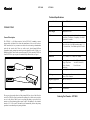
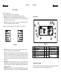
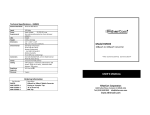
ETP 1010 ETP 1010 LEDs: Summary The ETP1010 has 14 LEDs. There is one LED per transceiver for each of the following: SQE, Indicates SQE switch is on. Should be off during normal operation. TXD, Indicates device is transmitting, should be on during normal operation. COL, Indicates presence of collisions. Normally off during “clear” transmission periods. Will clear when collisions stop. PWR, Indicates transceiver is properly receiving power from the network device to which it is connected through AUI port. Normally on. Key Features Both RJ45 Ports A & B have their own set of five LEDs for each of the following: Figure 2 Figure 5. REC Indicates that the port is receiving. Only one of the two ports should have the receive LED on during reception; the other should be off. LINK Indicates that a proper 10BaseT link has been established at the port. The active port’s Link LED should be the only one on during normal operation. If both LEDs are off, the transceiver is unable to establish a link at either port. The Link LED on the active or enabled port should be on if all connections have been made properly, if the cable is intact, and if the device on the other end of the cable is operational. ENABLE Indicates that the port is the one in use. Only one of the ports should on be in at any given time. During “hunt” periods both LEDs could appear to be on due to the rapid switching occurring as the transceiver searches for valid data. POLIRITY Indicates that the connection being made has the wrong polarity. Needs rewiring or use of crossover switch. Should normally be off. 1 2 3 4 5 6 7 AB, SQE & 2.5/10 Switches AUI Connector SQE LED TXD LED COL LED PWR LED Port B LEDs 8 9 10 11 12 13 Port B Cross-over switch Port B RJ45 Connector Port A RJ45 Connector Port A Cross-over switch Port A LEDs Link & Reduced Squelch Switches Inspection of Package: This package should contain the ETP1010, this manual. Examine the shipping container for obvious damage you believe occurred during shipment or delivery.